US1853384A - Belt winding machine - Google Patents
Belt winding machine Download PDFInfo
- Publication number
- US1853384A US1853384A US293130A US29313028A US1853384A US 1853384 A US1853384 A US 1853384A US 293130 A US293130 A US 293130A US 29313028 A US29313028 A US 29313028A US 1853384 A US1853384 A US 1853384A
- Authority
- US
- United States
- Prior art keywords
- belt
- mandrel
- roll
- winding
- guide
- Prior art date
- Legal status (The legal status is an assumption and is not a legal conclusion. Google has not performed a legal analysis and makes no representation as to the accuracy of the status listed.)
- Expired - Lifetime
Links
Images

Classifications
-
- B—PERFORMING OPERATIONS; TRANSPORTING
- B21—MECHANICAL METAL-WORKING WITHOUT ESSENTIALLY REMOVING MATERIAL; PUNCHING METAL
- B21C—MANUFACTURE OF METAL SHEETS, WIRE, RODS, TUBES, PROFILES OR LIKE SEMI-MANUFACTURED PRODUCTS OTHERWISE THAN BY ROLLING; AUXILIARY OPERATIONS USED IN CONNECTION WITH METAL-WORKING WITHOUT ESSENTIALLY REMOVING MATERIAL
- B21C47/00—Winding-up, coiling or winding-off metal wire, metal band or other flexible metal material characterised by features relevant to metal processing only
- B21C47/28—Drums or other coil-holders
- B21C47/30—Drums or other coil-holders expansible or contractible
Definitions
- BELT WINDING MACHINE Filed July 16 1928 4 Sheets-Sheet l flike/zfor AJZ9/d/ZZV1ZT 675001 April 12, 1932.
- A, SNOW BELT WINDING MACHINE Filed July 16 1928 4- Sheets-Sheet 2 fire/Mar llewwzrfwzoax HIM...
- This invention relates to a machine for winding belting or other similar products into rolls for storage or shipment.
- My invention further relates to the provision of convenient control and braking mechanism for sucha winding machine; to the provision of an improved device for gripping and releasing the end of the belt to be wound; to the provision of an improved collapsible mandrel on which to wind the belt; and to the provision of an improved belt guiding and pressure applying device.
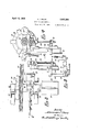
- FIG. 1 is a front elevation of my improved winding machine
- Fig. 2 is a detail plan view of the foot pedal and connections, looking in the direction of the arrow 2 in Fig. 1;
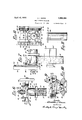
- Fig. 3 is a sectional plan view, taken along the line 33 in Fig. 1;
- Fig. 4 is a sectional front elevation, taken along the line 14 in Fig. 3';
- Fig. 5 is a detail side elevation, looking in the direction of the arrow 5 in Fig. 4;
- Fig. 6 is a sectional plan view, taken along the line 66 in Fig. 1;
- Fig. 7 is a. side elevation of certain parts, looking in the direction of the arrow 7 in Fig. 1;
- Fig. 8 is a front elevation of the same parts, looking in the direction of the arrow 8 in Fig. 7 1
- Fig. 9 is a plan view, partly in section, of an adjustable collar on the guide-roll;
- Fig. 10 is a detail sectional front elevation, taken along the line 10-1O in Fig. 9;
- Fig. 11 is a plan view of the guide-roll
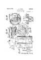
- Fig. 12 is a plan view of the winding mandrel
- Fig. 13 is an end elevation thereof, looking in the direction of the arrow 13 in Fig. 12;
- Fig. 14 is a sectional end elevationahtaken along the line 1 1-14 in Fig. 12; h
- Fig. 15 is a detail sectional plan View of certain parts, taken along the line 15-15 inFig.13;and 1 Fig. 16 is asectional'side elevation of certain parts, taken along the line 1616 in Fig. 12. 5
- my improved winding machine comprises a main shaft 20 supported in bearings'21 and 22 (Fig- 3) carried by a frame 24.
- a table T is posi tioned adjacent the winding machine and a foot-pedal 25 extends alongside the table and is mounted on arms 26 secured to a rock shaft 27.
- the rock shaft is mounted in suitable fixed bearings and is provided with a cross arm 30 (Fig. 5) which is connected to control the starting and stopping of the winding mechanism.
- f i A driven belt pulley 31 (Fig. 3) is loosely mounted on the winding shaft 20 adjacent a disc or flange 32 keyed to said shaft. frictiondisc 33 is interposed between the side surfaces of the pulley 31 and flange 32.
- One face of the bearing 22 is formed with inclined or spiral cam surfaces 3 1, engaged by similar projections 35 on the hub 36 of a control lever 37
- the 'lever37 is provided with a weight 37 which normally holds the parts in the position shown in Fig. 3, with the friction clutch released.
- a ball thrust bearing 38' is interposed between the hub 36 of the lever 37 and the hub 39 of the pul- I,
- the lever 37 is connected by links 40 (Figs. 4: and 5) to the rock arm 30 previously described.
- a spring 41 isconnected to the H rock arm 30 and assists the weight 37 in raising the rock arm and releasing the friction. 1
- the flange 32 has a cylindrical outer surface engaged by a brake-block 1 1 (Figs. 4
- This mandrel is of special construction and comprises a support 50 16) loosely mounted on the shaft 20 and having depending arms 51' supporting a stud 52. 1 V j
- the winding surface ,of the. mandrel is formed on two segmental shell members 53 and 54 (F ig. 14) having bearing portions loosely pivoted on the stud 52.
- a belt clamping member 55 (Fig. 14) is pivoted at 56-on an inwardly extending flange of the shell member 53.
- the depending arm 57 of said member 55 is connected by a spring 58 to the shell member 54, being secured at 61 to a corresponding flange 62'.
- the spring 58 thus acts to move the clamping device 55 to operative position and also todraw the shell members 53 and 54 toward each other.
- Similar inward flanges 64 and 66 are provided near the front ends of. the shell members 53' and 54, and these flanges 64 and 66 are provided with cam slots 67 (Fig.13).
- a cross arm 68 (Fig. 15) is keyedto the outer endof the shaft 20 and is secured thereon by a nut 69. Studs 70 project rearward from the cross arm 68 and extend into the cam I If the cross arm is rotated in the direction of the arrow 5 in Fig. 13, the studs will act to contract the mandrel and release the roll. of belting wound thereon. )Vhen the studs move in the opposite direction in the slots 67, they expand the mandrel.
- a latch 72 (Fig. 13) is pivoted at 73 on the cross ,arm 68 andis pressed yieldingly outward by a spring 74.
- a lug 75 is provided on the inside of the shell member 53 for engagement by the latch 72 when thecross arm is in theposition shown in Fig. 13, with the mandrel expanded. When it is desired to contract the mandrel, the latch 72 israised to clear the lug75.
- a guide-roll (Fig. 6) rotatable on a stud 81 which is secured in a guide-roll block 82 by a nut 83.
- the block 82 is slidable vertically between V-shaped guideways 84 mounted on the frame 24.
- a bolt 85 extends through an axial opening in the stud 81 and also through a collar 86 slidable on the outer end of the stud 81.
- a friction washer 87 is interposed between the'collar 86 and the face of an internal web 88 of the roll 80.
- a spring 89 encircles the opposite end of the bolt 85 and is adjustably secured thereon by a nut 90.
- the bolt 85 and spring 89 act through the collar 86 and washer 87 to yieldingly press the guide-roll axially against the outer face of the block 82.
- the roll 80 is thus rotatable against the adjustable friction of the washer 87.
- the roll 80 is provided with a fixed flange 92 (Fig. 11) at one end thereof and is also provided with a guide-collar 93 slidable thereon.
- a cam member 94 (Fig. 10) is pivoted at 95 on the collar 93 and is forced into yielding engagement with the roll 80 by a spring 96. l/Vhen the handle portion of the member 94 is pressed yieldingly inward, the collar may be easily adjusted axially of the roll 80, and when the member 94 is released, said member holds the collar firmly in adjusted position.
- the block 82 supports a stud 100 on which a hand wheel 101 is rotatably mounted.
- a pinion 102 is formed on the hub ofthehand to a portion of the frame 24. The pinion and hand wheel rotate freely on the stud lOO as the block 82 rises or falls.
- a second stud 110 (Fig. 6) is secured in permits the guide-plate to 1 .1 beyond norwheel 101 and engages a rack bar 103 secured the block 82 and forms a pivot for pawl 111 (Fig. 7) which engages the teeth of a ratchet bar 112, also secured to a portion of the frame 24. 6
- the pawl 111 slips idly past-the teet of the ratchet bar 112, but is held in yielding engagement therewith by a handle 114 which also actsas a weight for the pawl 111.
- the hand wheel 101 is rotated and the pinion 102, by its engagement with the fixed rack 103, moves the block 82 upward, carryingwith it the guide-roll 80.
- the pawl 111 holds the, guides tion of my improved Winding machine, it is believed that the method of operation and the advantages thereof will be readily apparent.
- the clamping member 55 is forced away from the edge of the shell member 53' by inserting a tool under the portion 57 of said member, and the end of the belt B is inserted as indicated in Fig. 14.
- the member 55 is then released and holds the belt firmly clamped in position.
- the cross bar 68 is then moved to the position indicated in Fig. 13, expanding the mandrel shell members 53 and 54, and the latch 72 locks the parts in expanded relation.
- the guide-roll is then lowered to engage the belt B as soon asthe roll begins to form, and the winding of the belt then proceeds under the control of the foot pedal 25, the operator starting and stopping the machine as desired and inspecting the belt as it passesover the table T.
- the cam movement of the cross arm 68 relative to the shell members 53' and 54 may be accomplished by the use of a suitable wrench or tool applied at the end of the mandrel and preferably engaging shoulders 120 (Fig. 13) on the members 53 and 54, thus turning the mandrel relative to the cross arm, which is fixed to the shaft 20 and which is held from rotation by the brake 44.
- a beltwinding machine having, in combination, a winding mandrel, means to secure the end of a beltthereto, means to rotate said mandrel, a table adjacent said winding machine over which the belt is drawn for inspection, and foot-operated controlling means for said winding machine, said means being mounted alongside said table and connected to said machine and being operable from any position alongside said table.
- a belt wind-ing machine having, in combination, a collapsible; winding mandrel, means to secure the end of .a belt thereto, means to rotate said mandrel, means to apply rolling pressure to the belt, means to guide the belt against transverse displacement as it is wound on said mandrel, and means to ex pand said mandrel from collapsed position.
- a belt winding machine having, in combination, a collapsible winding mandrel
- a belt winding machine having, in combination, a winding mandrel, means to secure the end of a'belt thereto, means to rotate said mandrel, a guide and presser roll resting on said roll of belt as. it. is wound on said mans drel, a substantially vertically movable sup-. port forsaid guide-rolh'manually operated means to raise and lower said support, and
- a belt winding machine having, in combination, a winding mandrel,means to secure the end of a belt thereto, meansto rotate said mandrel, a guide and presser roll resting on saidroll of belt as it is wound on said mandrel, a substantially vertically movable support for said guideroll, manually operated means to raise'and lowersaidsupport, and means to hold said support in raised position, said latter means being manually releasable to permit lowering of said roll.
- a belt winding machine having, in combination, a winding mandrel, means to secure the end of a belt thereto, means to rotate said mandrel, a guide and presser roll restingon said roll of belt, and friction means to retard. the rotation of said guide-roll.
- a belt windingmachine having, in combination, a collapsible Winding mandrel, means to secure the end of a belt thereto,
- a belt winding .machine having, in combination, a winding mandrel, means to secure the end of a' belt thereto, means to rotatesaid mandrel, a guide and presser roll resting on said roll of belt, a guide-collar on' said roll manually adjustable axially thereof to various fixed positions for different widths of belt, andcam means to secure-said collar inadjustedposition.
- a belt winding machine having, in combination, a winding mandrel, means to secure the end of abeltthereto, meansto rotate said iio ii's
- said roll of belt 'a guide-collar on said-roll manually adjustable axially thereof for different Widths of belt, and a belt engaging disc yieldingly mounted at one side of said collar and axially movable relative thereto to accommodate inequalitiesin belt Width.
- a Winding machine a shaft, a Windi-ng mandrel comprising a rotatable support, a pair of segmental shell members pivoted thereto, means mounted on said shaft, and movable relative to said members to expand and contract said members, and a belt gripping member mounted on one of said shell members and effective to secure the end of a piece of belt thereto.
- a Winding mandrel comprising a rotatable support, a pair ofsegmental shell members pivoted thereto, means mounted on said shaft, an'd movable relative to said members to expand andcontract said members, a belt gripping member mounted on one of said shell members and etfective to secure the end of a piece of beltthereto, and a spring to render said gripping member operative.
- a belt Windingmachine having in combination a Windingma-n-dre'l, means to secure the end of a belt thereto, means to rotate said mandrel, a guide and presser roll resting on saidroll of belt, and a guide collar on said roll manually adjustable axially thereof fordifferent Widths of belt, cam means to secure said collar in adjusted position, said collar having a yieldable Wall at one side thereof, axially movable relative thereto to accommodate inequalities in belt Width.
- a Winding mandrel comprising a rotatablesupport, a pair of segmental shell members fitted thereto, means to expand and contract said members, and a belt gripping member mounted on one of said shell members having a portion movable toward said shell member to secure the end of a piece of belt thereto, and means conmeeting said gripping member to the other of said shell members.
- a winding mandrel comprising a rotatable support, a pair of segmental shell members fitted thereto, means to expand and contract said members, a belt gripping member mounted on one of said shell members having a portion movable toward said shell member to secure the end of a piece of belt thereto, and a spring connecting'said gripping member to the other ofsaid shell members thereby to render said gripping member operative.
- a Winding mandrel comprising a rotatable support, a'pair of segmental shell members fitted thereto, means to expand and contract said members, a belt gripping member mounted on one of said shell members having a portion movable toward said shell member to secure the end of apiece of belt thereto, and-a spring to ron; der said gripping member operative, said spring being connected atone end to said gripping member andat its other end to the other shell member.
Landscapes
- Engineering & Computer Science (AREA)
- Mechanical Engineering (AREA)
- Winding Of Webs (AREA)
Description
April 12, 1932 I, NOW 1,853,384
BELT WINDING MACHINE Filed July 16 1928 4 Sheets-Sheet l flike/zfor AJZ9/d/ZZV1ZT 675001 April 12, 1932. A, SNOW BELT WINDING MACHINE Filed July 16 1928 4- Sheets-Sheet 2 lire/Mar llewwzrfwzoax HIM...
April 12, 1932. A. SNOW BELT WINDING MACHINE Fiied July 16, 1928 4-Sheets-Sheet w mw ' April 12, 1932. A. SNOW BELT WINDING MACHINE.
Filed July 16, 1928 4 Sheets-Sheet 4 rammed Apr. 12, 1932 UN TED STATES PATENT; rrlcsq ALEXANDER I. snow, or WORCESTER, MAS AC USETTS, ASSIGNOR To enATon-a KNIGHT COMPANY, or WORCESTER, MASSACHUSETTS, A CORPORATION or 'm ssA- CHUSETTS BELT WINDING MACHINE Application filed July 16, 1928. Serial No. 293.130.
This invention relates to a machine for winding belting or other similar products into rolls for storage or shipment.
It is the object of my invention to provide a machine in which such rolls, may be tightly and firmly wound and from which the rolls may be easily removed.
My invention further relates to the provision of convenient control and braking mechanism for sucha winding machine; to the provision of an improved device for gripping and releasing the end of the belt to be wound; to the provision of an improved collapsible mandrel on which to wind the belt; and to the provision of an improved belt guiding and pressure applying device.
My invention further relates toarrangements and combinations of parts which will be hereinafter described and more particularly pointed out in the appended claims.
A preferred form of the invention is shown in the drawings, in which Fig. 1 is a front elevation of my improved winding machine;
Fig. 2 is a detail plan view of the foot pedal and connections, looking in the direction of the arrow 2 in Fig. 1;
Fig. 3 is a sectional plan view, taken along the line 33 in Fig. 1;
Fig. 4 is a sectional front elevation, taken along the line 14 in Fig. 3';
Fig. 5 is a detail side elevation, looking in the direction of the arrow 5 in Fig. 4;
Fig. 6 is a sectional plan view, taken along the line 66 in Fig. 1;
Fig. 7 is a. side elevation of certain parts, looking in the direction of the arrow 7 in Fig. 1;
Fig. 8 is a front elevation of the same parts, looking in the direction of the arrow 8 in Fig. 7 1
Fig. 9 is a plan view, partly in section, of an adjustable collar on the guide-roll;
Fig. 10 is a detail sectional front elevation, taken along the line 10-1O in Fig. 9;
Fig. 11 is a plan view of the guide-roll;
Fig. 12 is a plan view of the winding mandrel;
Fig. 13 is an end elevation thereof, looking in the direction of the arrow 13 in Fig. 12;
Fig. 14: is a sectional end elevationahtaken along the line 1 1-14 in Fig. 12; h
Fig. 15 is a detail sectional plan View of certain parts, taken along the line 15-15 inFig.13;and 1 Fig. 16 is asectional'side elevation of certain parts, taken along the line 1616 in Fig. 12. 5
Referring to the drawings, my improved winding machine comprises a main shaft 20 supported in bearings'21 and 22 (Fig- 3) carried by a frame 24.. A table T is posi tioned adjacent the winding machine and a foot-pedal 25 extends alongside the table and is mounted on arms 26 secured to a rock shaft 27. The rock shaft is mounted in suitable fixed bearings and is provided with a cross arm 30 (Fig. 5) which is connected to control the starting and stopping of the winding mechanism.- f i A driven belt pulley 31 (Fig. 3) is loosely mounted on the winding shaft 20 adjacent a disc or flange 32 keyed to said shaft. frictiondisc 33 is interposed between the side surfaces of the pulley 31 and flange 32. i 7
One face of the bearing 22 is formed with inclined or spiral cam surfaces 3 1, engaged by similar projections 35 on the hub 36 of a control lever 37 The 'lever37 is provided with a weight 37 which normally holds the parts in the position shown in Fig. 3, with the friction clutch released. A ball thrust bearing 38'is interposed between the hub 36 of the lever 37 and the hub 39 of the pul- I,
The lever 37. is connected by links 40 (Figs. 4: and 5) to the rock arm 30 previously described. A spring 41 isconnected to the H rock arm 30 and assists the weight 37 in raising the rock arm and releasing the friction. 1
hen the pedal 25is depressed, the rock arm moves in the direction of' the arrow 0 (Fig. 5), swinging the control lever 37 in a counter-clockwise direction, and thus applying driving pressure to the friction disc 33.
The flange 32 has a cylindrical outer surface engaged bya brake-block 1 1 (Figs. 4
' slots 67 and 5) mounted at the upper end of a rod loosely slidable in a fixed bearing 46. At its lower end, the rod 45 is provided with nuts 48 engaged by an arm 49 on a rock shaft 50. A second arm 51 is connected by a link 52 to a stud 53 (Fig. 5) adjacent the hub of the rock arm 30.
As the arm is rocked to apply friction and start the winding shaft, the link 52 will be raised and the rod 45 lowered to release the brake-block 44. As soon as the foot pressure 20 and rotated thereby. This mandrel is of special construction and comprises a support 50 16) loosely mounted on the shaft 20 and having depending arms 51' supporting a stud 52. 1 V j The winding surface ,of the. mandrel is formed on two segmental shell members 53 and 54 (F ig. 14) having bearing portions loosely pivoted on the stud 52. A belt clamping member 55 (Fig. 14) is pivoted at 56-on an inwardly extending flange of the shell member 53. The depending arm 57 of said member 55 is connected by a spring 58 to the shell member 54, being secured at 61 to a corresponding flange 62'. The spring 58 thus acts to move the clamping device 55 to operative position and also todraw the shell members 53 and 54 toward each other.
Similar inward flanges 64 and 66 are provided near the front ends of. the shell members 53' and 54, and these flanges 64 and 66 are provided with cam slots 67 (Fig.13). A cross arm 68 (Fig. 15) is keyedto the outer endof the shaft 20 and is secured thereon by a nut 69. Studs 70 project rearward from the cross arm 68 and extend into the cam I If the cross arm is rotated in the direction of the arrow 5 in Fig. 13, the studs will act to contract the mandrel and release the roll. of belting wound thereon. )Vhen the studs move in the opposite direction in the slots 67, they expand the mandrel.
T A latch 72 (Fig. 13) is pivoted at 73 on the cross ,arm 68 andis pressed yieldingly outward by a spring 74. A lug 75 is provided on the inside of the shell member 53 for engagement by the latch 72 when thecross arm is in theposition shown in Fig. 13, with the mandrel expanded. When it is desired to contract the mandrel, the latch 72 israised to clear the lug75.
For guiding the belt to the mandrel and for exerting pressure on the roll of belting, I provide a guide-roll (Fig. 6) rotatable on a stud 81 which is secured in a guide-roll block 82 by a nut 83. The block 82 is slidable vertically between V-shaped guideways 84 mounted on the frame 24.
A bolt 85 extends through an axial opening in the stud 81 and also through a collar 86 slidable on the outer end of the stud 81. A friction washer 87 is interposed between the'collar 86 and the face of an internal web 88 of the roll 80. A spring 89 encircles the opposite end of the bolt 85 and is adjustably secured thereon by a nut 90. The bolt 85 and spring 89 act through the collar 86 and washer 87 to yieldingly press the guide-roll axially against the outer face of the block 82. The roll 80is thus rotatable against the adjustable friction of the washer 87.
The roll 80 is provided with a fixed flange 92 (Fig. 11) at one end thereof and is also provided with a guide-collar 93 slidable thereon. A cam member 94 (Fig. 10) is pivoted at 95 on the collar 93 and is forced into yielding engagement with the roll 80 by a spring 96. l/Vhen the handle portion of the member 94 is pressed yieldingly inward, the collar may be easily adjusted axially of the roll 80, and when the member 94 is released, said member holds the collar firmly in adjusted position.
'A guide-plate or disc 97 is mounted at the side of the collar 93 and is loosely secured thereto by screws 98. Springs 99 press the plate 97 yieldingly away from the collar 93. This construction yield slightly whenengaged by a portion of the belt which is of a little more than normal width, or the guide-plate may yield if the belt does not wind exactly straight on the roll, so that the roll is increased mal width. I r
The block 82 supports a stud 100 on which a hand wheel 101 is rotatably mounted. A pinion 102is formed on the hub ofthehand to a portion of the frame 24. The pinion and hand wheel rotate freely on the stud lOO as the block 82 rises or falls.
A second stud 110 (Fig. 6) is secured in permits the guide-plate to 1 .1 beyond norwheel 101 and engages a rack bar 103 secured the block 82 and forms a pivot for pawl 111 (Fig. 7) which engages the teeth of a ratchet bar 112, also secured to a portion of the frame 24. 6
As the block 82 is pushed upward by the increasing size of the roll of belting being wound, the pawl 111 slips idly past-the teet of the ratchet bar 112, but is held in yielding engagement therewith by a handle 114 which also actsas a weight for the pawl 111.
hen it is desired toraise the guide-roll for removal of a roll of belting, the hand wheel 101 is rotated and the pinion 102, by its engagement with the fixed rack 103, moves the block 82 upward, carryingwith it the guide-roll 80. The pawl 111 holds the, guides tion of my improved Winding machine, it is believed that the method of operation and the advantages thereof will be readily apparent.
The clamping member 55 is forced away from the edge of the shell member 53' by inserting a tool under the portion 57 of said member, and the end of the belt B is inserted as indicated in Fig. 14. The member 55 is then released and holds the belt firmly clamped in position. The cross bar 68 is then moved to the position indicated in Fig. 13, expanding the mandrel shell members 53 and 54, and the latch 72 locks the parts in expanded relation. The guide-roll is then lowered to engage the belt B as soon asthe roll begins to form, and the winding of the belt then proceeds under the control of the foot pedal 25, the operator starting and stopping the machine as desired and inspecting the belt as it passesover the table T.
lVhen the winding of the belt is complete, the end is secured in any convenient manner. The guide-roll is lifted away from the belting and the cross-bar 68 is turned in the direction of the arrow 6 in Fig. 13, moving the studs along the slots 67 and contracting the shell members 53 and 54, thereby loosening the belt on the mandrel. The clamping member 55 is then forced open and the roll is easily slipped off of the end of the mandrel, thus completing the cycle of operations of the machine.
The cam movement of the cross arm 68 relative to the shell members 53' and 54 may be accomplished by the use of a suitable wrench or tool applied at the end of the mandrel and preferably engaging shoulders 120 (Fig. 13) on the members 53 and 54, thus turning the mandrel relative to the cross arm, which is fixed to the shaft 20 and which is held from rotation by the brake 44.
Having thus described my invention and the advantages thereof, I do not wish to be limited to the details herein disclosed, otherwise than as set forth in the claims, but what I claim is 1. A beltwinding machine having, in combination, a winding mandrel, means to secure the end of a beltthereto, means to rotate said mandrel, a table adjacent said winding machine over which the belt is drawn for inspection, and foot-operated controlling means for said winding machine, said means being mounted alongside said table and connected to said machine and being operable from any position alongside said table.
. 2. A belt wind-ing machinehaving, in combination, a collapsible; winding mandrel, means to secure the end of .a belt thereto, means to rotate said mandrel, means to apply rolling pressure to the belt, means to guide the belt against transverse displacement as it is wound on said mandrel, and means to ex pand said mandrel from collapsed position.
3. ,A belt winding machine having, in combination, a collapsible winding mandrel,
means to expand and contract said mandrel,
means to secure the end of abelt thereto,
means to rotate said mandrel, and a guide and presserroll mounted on a vertically movable slide andresting by gravity on therollof belt as it is wound on said mandrel, said roll having means to guide the belt against transverse displacement.
4., A belt winding machine having, in combination, a winding mandrel, means to secure the end of a'belt thereto, means to rotate said mandrel, a guide and presser roll resting on said roll of belt as. it. is wound on said mans drel, a substantially vertically movable sup-. port forsaid guide-rolh'manually operated means to raise and lower said support, and
means to hold said support in raisedp'osition- 5. A belt winding machine having, in combination, a winding mandrel,means to secure the end of a belt thereto, meansto rotate said mandrel, a guide and presser roll resting on saidroll of belt as it is wound on said mandrel, a substantially vertically movable support for said guideroll, manually operated means to raise'and lowersaidsupport, and means to hold said support in raised position, said latter means being manually releasable to permit lowering of said roll.,
6. A belt winding machine having, in combination, a winding mandrel, means to secure the end of a belt thereto, means to rotate said mandrel,a guide and presser roll restingon said roll of belt, and friction means to retard. the rotation of said guide-roll.
7. A belt windingmachine having, in combination, a collapsible Winding mandrel, means to secure the end of a belt thereto,
means torotate said mandrel, a guide and.
presser roll resting on said roll of belt, and aguide-collar on said roll manually adj ustable axially thereof for different widthseof belt, and means to expand said mandrel from collapsed position. a I
8. A belt winding .machine having, in combination, a winding mandrel, means to secure the end of a' belt thereto, means to rotatesaid mandrel, a guide and presser roll resting on said roll of belt, a guide-collar on' said roll manually adjustable axially thereof to various fixed positions for different widths of belt, andcam means to secure-said collar inadjustedposition. L
9. A belt winding machine having, in combination, a winding mandrel, means to secure the end of abeltthereto, meansto rotate said iio ii's
said roll of belt,'a guide-collar on said-roll manually adjustable axially thereof for different Widths of belt, and a belt engaging disc yieldingly mounted at one side of said collar and axially movable relative thereto to accommodate inequalitiesin belt Width.
10. In a Winding machine, a shaft, a Windi-ng mandrel comprising a rotatable support, a pair of segmental shell members pivoted thereto, means mounted on said shaft, and movable relative to said members to expand and contract said members, and a belt gripping member mounted on one of said shell members and effective to secure the end of a piece of belt thereto. a
11. Ina winding machine, a shaft, a Winding mandrel comprising a rotatable support, a pair ofsegmental shell members pivoted thereto, means mounted on said shaft, an'd movable relative to said members to expand andcontract said members, a belt gripping member mounted on one of said shell members and etfective to secure the end of a piece of beltthereto, and a spring to render said gripping member operative.
12. A belt Windingmachine having in combination a Windingma-n-dre'l, means to secure the end of a belt thereto, means to rotate said mandrel, a guide and presser roll resting on saidroll of belt, and a guide collar on said roll manually adjustable axially thereof fordifferent Widths of belt, cam means to secure said collar in adjusted position, said collar having a yieldable Wall at one side thereof, axially movable relative thereto to accommodate inequalities in belt Width.
13. In a Winding machine, a Winding mandrel comprising a rotatablesupport, a pair of segmental shell members fitted thereto, means to expand and contract said members, and a belt gripping member mounted on one of said shell members having a portion movable toward said shell member to secure the end of a piece of belt thereto, and means conmeeting said gripping member to the other of said shell members.
, V 14. Ina Windingmachine, a winding mandrel comprising a rotatable support, a pair of segmental shell members fitted thereto, means to expand and contract said members, a belt gripping member mounted on one of said shell members having a portion movable toward said shell member to secure the end of a piece of belt thereto, and a spring connecting'said gripping member to the other ofsaid shell members thereby to render said gripping member operative.
15. In a Winding machine, a Winding mandrel comprising a rotatable support, a'pair of segmental shell members fitted thereto, means to expand and contract said members, a belt gripping member mounted on one of said shell members having a portion movable toward said shell member to secure the end of apiece of belt thereto, and-a spring to ron; der said gripping member operative, said spring being connected atone end to said gripping member andat its other end to the other shell member. 1
In testimony whereof: I have hereunto affixed my signature.
ALEXANDER LSNOW.
Priority Applications (1)
| Application Number | Priority Date | Filing Date | Title |
|---|---|---|---|
| US293130A US1853384A (en) | 1928-07-16 | 1928-07-16 | Belt winding machine |
Applications Claiming Priority (1)
| Application Number | Priority Date | Filing Date | Title |
|---|---|---|---|
| US293130A US1853384A (en) | 1928-07-16 | 1928-07-16 | Belt winding machine |
Publications (1)
| Publication Number | Publication Date |
|---|---|
| US1853384A true US1853384A (en) | 1932-04-12 |
Family
ID=23127779
Family Applications (1)
| Application Number | Title | Priority Date | Filing Date |
|---|---|---|---|
| US293130A Expired - Lifetime US1853384A (en) | 1928-07-16 | 1928-07-16 | Belt winding machine |
Country Status (1)
| Country | Link |
|---|---|
| US (1) | US1853384A (en) |
Cited By (5)
| Publication number | Priority date | Publication date | Assignee | Title |
|---|---|---|---|---|
| US2454213A (en) * | 1944-05-15 | 1948-11-16 | Diesel Filter Co | Apparatus for forming filter elements and the like |
| US2622820A (en) * | 1949-07-07 | 1952-12-23 | Western Electric Co | Apparatus for handling strip material |
| US4160531A (en) * | 1977-10-25 | 1979-07-10 | Brammall, Inc. | Apparatus and methods for untelescoping and rewinding reels of sheet material such as steel |
| US5653400A (en) * | 1995-01-12 | 1997-08-05 | Nishimura Seisakusho Co., Ltd. | Winding apparatus |
| US5727747A (en) * | 1993-09-23 | 1998-03-17 | Msk-Verpackungs-Systeme Gmbh | Method and device for removing a foil wrapping drawn over a stack of goods |
-
1928
- 1928-07-16 US US293130A patent/US1853384A/en not_active Expired - Lifetime
Cited By (5)
| Publication number | Priority date | Publication date | Assignee | Title |
|---|---|---|---|---|
| US2454213A (en) * | 1944-05-15 | 1948-11-16 | Diesel Filter Co | Apparatus for forming filter elements and the like |
| US2622820A (en) * | 1949-07-07 | 1952-12-23 | Western Electric Co | Apparatus for handling strip material |
| US4160531A (en) * | 1977-10-25 | 1979-07-10 | Brammall, Inc. | Apparatus and methods for untelescoping and rewinding reels of sheet material such as steel |
| US5727747A (en) * | 1993-09-23 | 1998-03-17 | Msk-Verpackungs-Systeme Gmbh | Method and device for removing a foil wrapping drawn over a stack of goods |
| US5653400A (en) * | 1995-01-12 | 1997-08-05 | Nishimura Seisakusho Co., Ltd. | Winding apparatus |
Similar Documents
| Publication | Publication Date | Title |
|---|---|---|
| US3910517A (en) | Mandrel-less winder | |
| US3202374A (en) | Web winding machinery | |
| US1853384A (en) | Belt winding machine | |
| US2670152A (en) | Rewinding machine | |
| US2125660A (en) | Strip reel | |
| US1467841A (en) | Automatic sheet winding and measuring machine | |
| US1603017A (en) | Reel | |
| US1747289A (en) | Roll-shifting apparatus | |
| US2168023A (en) | Automatic brake mechanism for feeding material from a roll | |
| US1499307A (en) | Feeding and winding machine | |
| US798241A (en) | Machine for winding paper. | |
| US2762418A (en) | Method and apparatus for unwrapping a coil of metal stock | |
| US1396179A (en) | Lined-pipe-flange-forming machine | |
| US1861374A (en) | Winding machine for rolling roofing paper | |
| US1988439A (en) | Strip metal winding block | |
| US1345459A (en) | Apparatus for forming tubes | |
| US2447604A (en) | Fiber roll former | |
| US311261A (en) | Paper | |
| US1859117A (en) | Take-up block | |
| US2035739A (en) | Ball winding machine | |
| US1489874A (en) | Delivering material from rolls | |
| US1728511A (en) | Tread-applying device for tire-making machines | |
| US1720833A (en) | Machine for rolling rims and other annular objects | |
| US1437573A (en) | Barrel-forming machine | |
| US2144264A (en) | Process of making steel wool pads and apparatus |