US1853338A - Automatic door draft stop - Google Patents
Automatic door draft stop Download PDFInfo
- Publication number
- US1853338A US1853338A US452653A US45265330A US1853338A US 1853338 A US1853338 A US 1853338A US 452653 A US452653 A US 452653A US 45265330 A US45265330 A US 45265330A US 1853338 A US1853338 A US 1853338A
- Authority
- US
- United States
- Prior art keywords
- movable member
- door
- secured
- guides
- pins
- Prior art date
- Legal status (The legal status is an assumption and is not a legal conclusion. Google has not performed a legal analysis and makes no representation as to the accuracy of the status listed.)
- Expired - Lifetime
Links
- 239000011324 bead Substances 0.000 description 4
- 238000010276 construction Methods 0.000 description 4
- 239000002184 metal Substances 0.000 description 3
- 239000003795 chemical substances by application Substances 0.000 description 1
- 239000000463 material Substances 0.000 description 1
- 238000012986 modification Methods 0.000 description 1
- 230000004048 modification Effects 0.000 description 1
- 230000009972 noncorrosive effect Effects 0.000 description 1
- 230000002441 reversible effect Effects 0.000 description 1
Images
Classifications
-
- E—FIXED CONSTRUCTIONS
- E06—DOORS, WINDOWS, SHUTTERS, OR ROLLER BLINDS IN GENERAL; LADDERS
- E06B—FIXED OR MOVABLE CLOSURES FOR OPENINGS IN BUILDINGS, VEHICLES, FENCES OR LIKE ENCLOSURES IN GENERAL, e.g. DOORS, WINDOWS, BLINDS, GATES
- E06B7/00—Special arrangements or measures in connection with doors or windows
- E06B7/16—Sealing arrangements on wings or parts co-operating with the wings
- E06B7/18—Sealing arrangements on wings or parts co-operating with the wings by means of movable edgings, e.g. draught sealings additionally used for bolting, e.g. by spring force or with operating lever
- E06B7/20—Sealing arrangements on wings or parts co-operating with the wings by means of movable edgings, e.g. draught sealings additionally used for bolting, e.g. by spring force or with operating lever automatically withdrawn when the wing is opened, e.g. by means of magnetic attraction, a pin or an inclined surface, especially for sills
Definitions
- One object of the invention is the production of a device which is automatically operated by opening and'closing a door.
- Another object of the invention is the pro- 6 vision of a device which may be adjusted to operate in either of twodirections, thereby allowing the device to be atfixed to a door regardless of which edge of the door is hinged to a door casing.
- a further object of the invention is the novel arrangement or association of parts which are employed to produce the new and improved mode by which the device is operated. 7 Another object of the invention is the production of a device that issimple, inexpensive, compact, attractive, durable, eflicient and satisfactory for use wherever found applicable.
- a still further object of the invention is to provide a novel and improved means for guiding the movable member relatively. the stationary member.
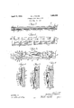
- Fig. l is a view in elevation showing the device associated withthe'lower part of a door, with the door in a closed position;
- Fig. 2 is a section taken substantially on the line 22 of Fig.1;
- Fig. 3 is a rear plan view of the device in elevation, V
- Fig. 4 is an enlarged sectional view taken substantially on the line H of Fig. 3, showing the position of the movable member relatively the stationary member when the device is in inoperative position;
- Fig. 5 is an enlarged sectional view taken substantially on line 55 of Fig. 3, showing the movable member in extended position in contact with a door sill;
- Fig. 6 is a section taken substantially on ne 66 of Fig. 3, clearly showing the novel draft excluding element which will herein- 1930.
- the device generally designated 1 is shown adapted for association with a door 2 which is hinged as at between the door casings 3.. Any suitable means may be employed for securing the device to a door. Suitable door stops 5 are secured to the inner faces of the casings 3. Numeral 6 indicates adoor sill.
- the stationary member or part of the device generally designated 7, preferably'coms prises a strip of non-corrosive metal of a length substantially equal to the Width of a door.
- This stationary membergenerally designated 7 includes a fiat flange-attaching portion 8 which is curved over to provide a bead portion 8 which bears against the door.
- This member is formed into a sort of housing portion 9, and is further bent downwardly as indicated at 10, and formed with a bead 10".
- This bead 10 is adapted for contact with the draft excluding element to prevent the circu- I lation of air between the stationary member and movable member of the device.
- One of the means whereby the movable member of the device is shifted or guided consists of spaced guides 11 which are suitably secured by rivets 12or other means to the flange-attaching portion 8 of the stationary member;
- Each guide is formed with flat bearing portions 13 and 14, and a raised centralportion 15, the object of which is to provide a space in which a part of the movable mechanism of the. device may operate.
- This particularform of guide also serves as a bracing agent and urges the movable member and after be described, againstthe bead portion 0 10 of the stationary member.
- Provided in the raised central portionv 15 of the guides 11, are angular two-way cam slots 17, the object of which is to provide the means for shifting and guiding the movable member of the device in either of two directions.
- the movable member of the device is preferably made of metal' and includes a flat portion 19 and a portion such as 20, which is formed to secure thereto, a draft excluding element 21.
- Secured to this movable member, generaly designated 18, are pins 22, arranged for engagement Within the two-way cam slots 17 of the guides 11. As shown, these pins are headed over or flanged, as at 23, to thereby prevent the movable member from being detached from the guides. It will thus be evident that unique means are provided whereby the movable member may be shifted in either of two directions by reason of the-pins-ridmg in the cam slots.
- One particular object of such a construction is to decrease the amount of friction when several of the ,parts aremoved.
- an angularly shaped lug Secured by any suitable means to the flange-attaching portion 8 of the stationary member, is an angularly shaped lug, generally designated 24, which consists of the flat ,portion 25 and 'an angular ,portion .26, the latter being provided with ane-yeor hole 27.
- the spring may be :adjusted to one of two positions, to thereby move the movable member .in either of twomlirections; pins QQ-beingndaptd .for a prescribed-movement in thecam slots 17.
- thespring is secured in either of said positions, one end such as '31 of .the .movable member always adapted'toextendbeyond oneendof thesta- .tionary member.
- Adevice including two members, slotted guides secured to one of said members, pins mounted on the other .member arranged .in said slots, and a spring arrangement for moving the other member longitudinally and transversely of said first-mentioned member all! either of two directions.
- .2. .A device including two members, of which one has .spacedslotted guides afiixed thereto, and the other having spaced lugs and pins associated therewith, said pins being adapted for movement in said slots, a spring having one end secured to one memher and the other end adapted for association with either of said lugs to thereby cause one member to be moved longitudinally and transversely of :the other to an inoperative position in either of two directions.
- a device including two members, of which one has spaced guides thereon, said guides having offset ends, two-way slots provided in said guides between the said oifset .ends pins secured to the other member and engageable with said slots to thereby allow one member -.to be moved longitudinallyi and transversely of the other in either of two directions, .a spring, means for securing .one end of said spring toonemember and means ,for securing the other .end of said spring to the other member.
- a device comprisinga stationary member formed with a flanged attaching ,portion, a housing portion, and an inwardly extending guide portion,..a plurality-of slottedguide members mounted on the ifiange attaching .portion, a movable member :having .a draft excluding element secured thereto interposed between the housing portion and the guides, said movable .member having pins .afiixed thereto for'engagement with theslots .in .said guides, said draft excluding element adapted ior frictional contact with said inwardly extending guide portion, alug securedtosaid flange attaching portion, a spring'zhaving one .endsecured tosaid lug, and spaced means ,providedonthemovable member wherebythe position of the spring may be reversed to secure the freerend of thesame .to either of saidimeansfto therebycausethe movablememher to be moved longitudinally .and transversely of
- a device including two members :made of relatively thin material, of which one has spaced slotted guides .aflixed thereto, and the other being movable and having a draft excludingelemenaspaced lugs,and pins associated therewith, said pins being secured and adapted for movement in said slots aispring secured to one member and :adapted for reversible association with either of said lugs, to thereby cause the movable member to be moved longitudinally and transverselyof the otherin either of two directions to an inoperativeposition.
- a device including two members, of which one is movable and is'provided with a draft excluding element-secured thereto, and means including slotted guides, pins, and a spring arrangement for constantly urging the movable member longitudinally and transversely of the other to an inoperative position in either oftwo directionswith'the draft excluding element being adapted for frictional contact with the other member.
- a device including a stationary member formed with a flange attaching portion and a housing portion, av plurality of slotted guide members mounted on the flange attach ing portion, said guide members provided with offsetend portions, a movable member having a draft excluding element secured thereto interposed between the housing portion and the guides, said movable member having pins affixed thereto for engagement with the slots in said guides, a lug secured to said flange attaching portion, a spring having one end secured to said lug, spaced means provided on the movable member whereby the position of the spring may be reversed to secure the free end of the same to either of said means to thereby constantly urge the movable member longitudinally and transversely of the stationary member to an inoperative position in either of two directions.
- a device including a stationary member, slotted guides secured to said stationary member, a movable member, pins carried by said movable member, said movable member beingadapted for longitudinal and transverse movement in either of two directions relatively said stationary member by reason of said pins being movable in said slots, and means provided for constantly urging said movable member to an inoperative position regardless of either direction, said movable member is adapted to be moved.
- Patent No. 1,853,338 Granted April 12, 1932, to
- the invention relates to devices known in the art; as door weather strips, and concerns primarily, an automatically operable device adapted for association with the lower part of a door, to thereby serve as a sealing agent to exclude air, dust, snow, etc., from entering a room through the space between the bottom of the door and the door sill, or floor.;
Landscapes
- Engineering & Computer Science (AREA)
- Civil Engineering (AREA)
- Structural Engineering (AREA)
- Specific Sealing Or Ventilating Devices For Doors And Windows (AREA)
Description
7 April 12, 1932. DENNls 1,853,338
AUTOMATIC DOOR DRAFT STOP Filed May 15, 1930 (If/i595 5:
Patented Apr.:12,j 1932v UNITED STATES WILLIAM J'. DENNIS, OF CHICAGO, ILLINOIS AUTOMATIC DOOR DRAFT STOP Application filed my 15,
One object of the invention is the production of a device which is automatically operated by opening and'closing a door.
-' Another object of the invention is the pro- 6 vision of a device which may be adjusted to operate in either of twodirections, thereby allowing the device to be atfixed to a door regardless of which edge of the door is hinged to a door casing.
A further object of the invention is the novel arrangement or association of parts which are employed to produce the new and improved mode by which the device is operated. 7 Another object of the invention is the production of a device that issimple, inexpensive, compact, attractive, durable, eflicient and satisfactory for use wherever found applicable.
A still further object of the invention is to provide a novel and improved means for guiding the movable member relatively. the stationary member.
Many other objects and advantages of the construction herein shown and described will be obvious to those skilled in the art'from the disclosure herein given;
To this end my invention consists in the novel construction, arrangement and combination of parts herein set forthin the drawings wherein the parts of the device are indicated by numerals:
Fig. l is a view in elevation showing the device associated withthe'lower part of a door, with the door in a closed position;
Fig. 2 is a section taken substantially on the line 22 of Fig.1;
Fig. 3 is a rear plan view of the device in elevation, V
Fig. 4: is an enlarged sectional view taken substantially on the line H of Fig. 3, showing the position of the movable member relatively the stationary member when the device is in inoperative position;
Fig. 5 is an enlarged sectional view taken substantially on line 55 of Fig. 3, showing the movable member in extended position in contact with a door sill; and
Fig. 6 is a section taken substantially on ne 66 of Fig. 3, clearly showing the novel draft excluding element which will herein- 1930. Serial No. 452,653.
means which are employed for guiding and operating the movable member in either of two directions.
With reference to the drawings, the device generally designated 1 is shown adapted for association with a door 2 which is hinged as at between the door casings 3.. Any suitable means may be employed for securing the device to a door. Suitable door stops 5 are secured to the inner faces of the casings 3. Numeral 6 indicates adoor sill.
The stationary member or part of the device generally designated 7, preferably'coms prises a strip of non-corrosive metal of a length substantially equal to the Width of a door. This stationary membergenerally designated 7 includes a fiat flange-attaching portion 8 which is curved over to provide a bead portion 8 which bears against the door. This member is formed into a sort of housing portion 9, and is further bent downwardly as indicated at 10, and formed with a bead 10". This bead 10 is adapted for contact with the draft excluding element to prevent the circu- I lation of air between the stationary member and movable member of the device.
One of the means whereby the movable member of the device is shifted or guided, consists of spaced guides 11 which are suitably secured by rivets 12or other means to the flange-attaching portion 8 of the stationary member; Each guide is formed with flat bearing portions 13 and 14, and a raised centralportion 15, the object of which is to provide a space in which a part of the movable mechanism of the. device may operate. This particularform of guide also serves as a bracing agent and urges the movable member and after be described, againstthe bead portion 0 10 of the stationary member. Provided in the raised central portionv 15 of the guides 11, are angular two-way cam slots 17, the object of which is to provide the means for shifting and guiding the movable member of the device in either of two directions.
The movable member of the device, generally designated 18 is preferably made of metal' and includes a flat portion 19 and a portion such as 20, which is formed to secure thereto, a draft excluding element 21. Secured to this movable member, generaly designated 18, are pins 22, arranged for engagement Within the two-way cam slots 17 of the guides 11. As shown, these pins are headed over or flanged, as at 23, to thereby prevent the movable member from being detached from the guides. It will thus be evident that unique means are provided whereby the movable member may be shifted in either of two directions by reason of the-pins-ridmg in the cam slots. One particular object of such a construction, is to decrease the amount of friction when several of the ,parts aremoved.
Secured by any suitable means to the flange-attaching portion 8 of the stationary member, is an angularly shaped lug, generally designated 24, which consists of the flat ,portion 25 and 'an angular ,portion .26, the latter being provided with ane-yeor hole 27. Qne end of the spring 28 is secured in the eye 27=of the lug and the other end of the spring 28 is adapted for interchangeable as ,sociation with either of the lugs 29 and '30, whichiare suit-ablysecured-tothe flat portion 19 of the :movable member. It will .thus be apparentthat the spring may be :adjusted to one of two positions, to thereby move the movable member .in either of twomlirections; pins QQ-beingndapted .for a prescribed-movement in thecam slots 17. When thespring .is secured in either of said positions, one end such as '31 of .the .movable member always adapted'toextendbeyond oneendof thesta- .tionary member.
Erom the.abovedescriptiomit will beclear that-.theidevicemay beadjusted and-ailixed .to the lower part of .the door withone end such as 31, adapted when the -dOOl'ElSC1OS8( l,.t() contact a metal. guard iplatef32, which .may be secured to a stop 5, to thereby .operateainov- .able .member longitudinallyand transversely of :the stationary vmember, so that the draft excluding .element will engage a door sill 6 .to thereby prevent [circulation of air between thebottom of the .dooinand said sill.
AHaving thus \described my invention, it is obvious that various immaterial modifications may be made in the same without departing from the spirit of .my invention;
hence, I do not wish to be understood as limiting myself to the exact form, construction, arrangement and combination of parts herein shown and described or uses ,mentioned.
What I claim asnew and-desire to secure by .Letters \Patent is:
1. Adevice including two members, slotted guides secured to one of said members, pins mounted on the other .member arranged .in said slots, and a spring arrangement for moving the other member longitudinally and transversely of said first-mentioned member all! either of two directions.
.2. .A device including two members, of which one has .spacedslotted guides afiixed thereto, and the other having spaced lugs and pins associated therewith, said pins being adapted for movement in said slots, a spring having one end secured to one memher and the other end adapted for association with either of said lugs to thereby cause one member to be moved longitudinally and transversely of :the other to an inoperative position in either of two directions.
3. A device including two members, of which one has spaced guides thereon, said guides having offset ends, two-way slots provided in said guides between the said oifset .ends pins secured to the other member and engageable with said slots to thereby allow one member -.to be moved longitudinallyi and transversely of the other in either of two directions, .a spring, means for securing .one end of said spring toonemember and means ,for securing the other .end of said spring to the other member.
4. A device .comprisinga stationary member formed with a flanged attaching ,portion, a housing portion, and an inwardly extending guide portion,..a plurality-of slottedguide members mounted on the ifiange attaching .portion, a movable member :having .a draft excluding element secured thereto interposed between the housing portion and the guides, said movable .member having pins .afiixed thereto for'engagement with theslots .in .said guides, said draft excluding element adapted ior frictional contact with said inwardly extending guide portion, alug securedtosaid flange attaching portion, a spring'zhaving one .endsecured tosaid lug, and spaced means ,providedonthemovable member wherebythe position of the spring may be reversed to secure the freerend of thesame .to either of saidimeansfto therebycausethe movablememher to be moved longitudinally .and transversely of the stationary member to an inoperative ;position.in either of two directions.
.5. A device including two members :made of relatively thin material, of which one has spaced slotted guides .aflixed thereto, and the other being movable and having a draft excludingelemenaspaced lugs,and pins associated therewith, said pins being secured and adapted for movement in said slots aispring secured to one member and :adapted for reversible association with either of said lugs, to thereby cause the movable member to be moved longitudinally and transverselyof the otherin either of two directions to an inoperativeposition.
6. A device including two members, of which one is movable and is'provided with a draft excluding element-secured thereto, and means including slotted guides, pins, and a spring arrangement for constantly urging the movable member longitudinally and transversely of the other to an inoperative position in either oftwo directionswith'the draft excluding element being adapted for frictional contact with the other member.
7. A device including a stationary member formed with a flange attaching portion and a housing portion, av plurality of slotted guide members mounted on the flange attach ing portion, said guide members provided with offsetend portions, a movable member having a draft excluding element secured thereto interposed between the housing portion and the guides, said movable member having pins affixed thereto for engagement with the slots in said guides, a lug secured to said flange attaching portion, a spring having one end secured to said lug, spaced means provided on the movable member whereby the position of the spring may be reversed to secure the free end of the same to either of said means to thereby constantly urge the movable member longitudinally and transversely of the stationary member to an inoperative position in either of two directions. i 8. A device including a stationary member, slotted guides secured to said stationary member, a movable member, pins carried by said movable member, said movable member beingadapted for longitudinal and transverse movement in either of two directions relatively said stationary member by reason of said pins being movable in said slots, and means provided for constantly urging said movable member to an inoperative position regardless of either direction, said movable member is adapted to be moved.
In witness whereof, I hereunto subscribe my name this 29th dayof April A. D., 1930.
WILLIAM J. DENNIS.
CERTIFICATE OF CORRECTION.
Patent No. 1,853,338. Granted April 12, 1932, to
WILLIAM J. DENNIS.
It is hereby certified that error appears in the printed specification of .the above numbered patent requiring correction as follows: Page 1, before line 1, insert the following paragragh:-
The invention relates to devices known in the art; as door weather strips, and concerns primarily, an automatically operable device adapted for association with the lower part of a door, to thereby serve as a sealing agent to exclude air, dust, snow, etc., from entering a room through the space between the bottom of the door and the door sill, or floor.;
and that the said Letters Patent should be read with this correction therein that the same may conform to the record of the case in the Patent Office.
Signed and sealed this 31st day of May, A. D. 1932.
M. J. Moore, (Seal) Acting Commissioner of Patents.
Priority Applications (1)
| Application Number | Priority Date | Filing Date | Title |
|---|---|---|---|
| US452653A US1853338A (en) | 1930-05-15 | 1930-05-15 | Automatic door draft stop |
Applications Claiming Priority (1)
| Application Number | Priority Date | Filing Date | Title |
|---|---|---|---|
| US452653A US1853338A (en) | 1930-05-15 | 1930-05-15 | Automatic door draft stop |
Publications (1)
| Publication Number | Publication Date |
|---|---|
| US1853338A true US1853338A (en) | 1932-04-12 |
Family
ID=23797337
Family Applications (1)
| Application Number | Title | Priority Date | Filing Date |
|---|---|---|---|
| US452653A Expired - Lifetime US1853338A (en) | 1930-05-15 | 1930-05-15 | Automatic door draft stop |
Country Status (1)
| Country | Link |
|---|---|
| US (1) | US1853338A (en) |
Cited By (4)
| Publication number | Priority date | Publication date | Assignee | Title |
|---|---|---|---|---|
| US3030674A (en) * | 1960-11-09 | 1962-04-24 | Reese Metal Weather Strip Co | Sealing apparatus |
| US4406088A (en) * | 1981-11-09 | 1983-09-27 | Berndt Jr Fred P | Door bottom sealing apparatus |
| US6125584A (en) * | 1994-12-29 | 2000-10-03 | Pemko Manufacturing Co. | Automatic door bottom |
| US20090077895A1 (en) * | 2007-09-26 | 2009-03-26 | Adi Tshai | Automatic door bottom with release mechanism |
-
1930
- 1930-05-15 US US452653A patent/US1853338A/en not_active Expired - Lifetime
Cited By (5)
| Publication number | Priority date | Publication date | Assignee | Title |
|---|---|---|---|---|
| US3030674A (en) * | 1960-11-09 | 1962-04-24 | Reese Metal Weather Strip Co | Sealing apparatus |
| US4406088A (en) * | 1981-11-09 | 1983-09-27 | Berndt Jr Fred P | Door bottom sealing apparatus |
| US6125584A (en) * | 1994-12-29 | 2000-10-03 | Pemko Manufacturing Co. | Automatic door bottom |
| US20090077895A1 (en) * | 2007-09-26 | 2009-03-26 | Adi Tshai | Automatic door bottom with release mechanism |
| US8745924B2 (en) * | 2007-09-26 | 2014-06-10 | Zero International, Inc. | Automatic door bottom with release mechanism |
Similar Documents
| Publication | Publication Date | Title |
|---|---|---|
| US1853338A (en) | Automatic door draft stop | |
| MX2989E (en) | IMPROVED SLIDING GATE MECHANISM FOR A FUND CASTING CONTAINER | |
| US1973210A (en) | Automatic compensating device for sealing openings around doors, windows, and the like | |
| US1603409A (en) | Attachment for doors and the like | |
| US1948108A (en) | Weather strip | |
| US2620535A (en) | Slide fastener | |
| US1682389A (en) | Weather strip | |
| US1699611A (en) | Automatic door draft stop | |
| US733295A (en) | Weather-strip. | |
| US3328918A (en) | Vehicle body | |
| US1881114A (en) | Door closer | |
| US1728453A (en) | Weather strip | |
| US1109744A (en) | Guard-curtain for vestibule-cars. | |
| US1256052A (en) | Weatehr-strip. | |
| US1906110A (en) | Weather strip | |
| US1847958A (en) | Sash guide | |
| US858544A (en) | Combined weather-strip and window-supporter. | |
| US832924A (en) | Headlight-casing. | |
| US1475916A (en) | Buffer | |
| US1731626A (en) | Clutch mechanism | |
| US1451315A (en) | Hook fastener | |
| US1592515A (en) | Antifriction window-sash support | |
| US754857A (en) | Weather-strip. | |
| US1494785A (en) | Weather stripping | |
| US883603A (en) | Weather-strip. |