US1853337A - Traveling pouring pot for pipe coatings - Google Patents
Traveling pouring pot for pipe coatings Download PDFInfo
- Publication number
- US1853337A US1853337A US461139A US46113930A US1853337A US 1853337 A US1853337 A US 1853337A US 461139 A US461139 A US 461139A US 46113930 A US46113930 A US 46113930A US 1853337 A US1853337 A US 1853337A
- Authority
- US
- United States
- Prior art keywords
- pipe
- traveling
- wall
- receptacle
- spout
- Prior art date
- Legal status (The legal status is an assumption and is not a legal conclusion. Google has not performed a legal analysis and makes no representation as to the accuracy of the status listed.)
- Expired - Lifetime
Links
- 238000000576 coating method Methods 0.000 title description 6
- 239000011248 coating agent Substances 0.000 description 5
- 239000007788 liquid Substances 0.000 description 5
- 239000000463 material Substances 0.000 description 4
- 239000010426 asphalt Substances 0.000 description 3
- 239000007787 solid Substances 0.000 description 3
- 229920000742 Cotton Polymers 0.000 description 2
- 230000006378 damage Effects 0.000 description 2
- 239000000945 filler Substances 0.000 description 2
- 238000000034 method Methods 0.000 description 2
- 239000003755 preservative agent Substances 0.000 description 2
- 230000002335 preservative effect Effects 0.000 description 2
- 238000003466 welding Methods 0.000 description 2
- RYGMFSIKBFXOCR-UHFFFAOYSA-N Copper Chemical compound [Cu] RYGMFSIKBFXOCR-UHFFFAOYSA-N 0.000 description 1
- CVRALZAYCYJELZ-UHFFFAOYSA-N O-(4-bromo-2,5-dichlorophenyl) O-methyl phenylphosphonothioate Chemical compound C=1C=CC=CC=1P(=S)(OC)OC1=CC(Cl)=C(Br)C=C1Cl CVRALZAYCYJELZ-UHFFFAOYSA-N 0.000 description 1
- 241000364021 Tulsa Species 0.000 description 1
- 208000027418 Wounds and injury Diseases 0.000 description 1
- 230000000295 complement effect Effects 0.000 description 1
- 230000006866 deterioration Effects 0.000 description 1
- 210000005069 ears Anatomy 0.000 description 1
- 230000003028 elevating effect Effects 0.000 description 1
- 239000003517 fume Substances 0.000 description 1
- 208000014674 injury Diseases 0.000 description 1
- 239000003209 petroleum derivative Substances 0.000 description 1
- 239000000779 smoke Substances 0.000 description 1
- 239000002699 waste material Substances 0.000 description 1
Images
Classifications
-
- B—PERFORMING OPERATIONS; TRANSPORTING
- B05—SPRAYING OR ATOMISING IN GENERAL; APPLYING FLUENT MATERIALS TO SURFACES, IN GENERAL
- B05C—APPARATUS FOR APPLYING FLUENT MATERIALS TO SURFACES, IN GENERAL
- B05C5/00—Apparatus in which liquid or other fluent material is projected, poured or allowed to flow on to the surface of the work
-
- Y—GENERAL TAGGING OF NEW TECHNOLOGICAL DEVELOPMENTS; GENERAL TAGGING OF CROSS-SECTIONAL TECHNOLOGIES SPANNING OVER SEVERAL SECTIONS OF THE IPC; TECHNICAL SUBJECTS COVERED BY FORMER USPC CROSS-REFERENCE ART COLLECTIONS [XRACs] AND DIGESTS
- Y10—TECHNICAL SUBJECTS COVERED BY FORMER USPC
- Y10S—TECHNICAL SUBJECTS COVERED BY FORMER USPC CROSS-REFERENCE ART COLLECTIONS [XRACs] AND DIGESTS
- Y10S118/00—Coating apparatus
- Y10S118/11—Pipe and tube outside
Definitions
- My invention relates to pipe coating Inachines and more particularly to a device.
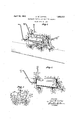
- Fig. 1 is a perspective view of a traveling pouring pot, embodying my invention mounted on a pipe line.
- Fig. 2 is a central longitudinal section of the device.
- Fig. 3 is a central cross section of the pouring pot illustrating, particularly, the conextending transversely through the ears, the
- brackets on opposite ends of the sills being formed to converge inwardly so that the rollers will be on an approximately radial 1930.
- the cross members near their ends, include horizontal portions 15 secured to the webs 'of the cross members b .bolts 16.
- the outer ends of the frame mem rs are bent upwardly at right angles to the horizontal portions to form standards 17 and 18 for supporting a vat or receptacle 19 adapted to contain the coating liquid.
- the receptacle preferably and rear walls 21 and 22, an inclined arcuate bottom 23 terminating in side walls 24, and a cover 25 having an outer vertical flange 26 and aninwardly directed and downwardly inc ined flange 27 covering the greater portion of the vat, so that pouring of liquid through the filler opening 28 defined by the inclined flange will be facilitated, and splash ing of liquid from the receptacle will be prevented.
- Fumes and smoke which may collect in the receptacle when hot liquid is employed are conducted therefrom through a vertical conduit 29, fixed in an opening 30 in the inclined.
- the rear wall 22 is provided adjacent its bottom with a rectangular outlet opening 31 surrounded by an outwardly extending flange 32, the outlet openin being controlled by a gate 33 vertically slida le between guide flanges 34 secured by welding or the like to the inner face of the rear end wall.
- the gate 33 is pivotally secured b a pin 43 'to an angle bracket 44 fixed to e contro the upper end of the bar being ivotalsecured to the control lever by a It 45.
- a spreader spout 46 is preferably ivotally mounted over, the outlet flange 32 y a bolt 47 extended transversely throu h the side -walls of the flan d opening an through a neck portion 48 o the spout.
- the s out preferably includes a solid bottom we 49, and an upper wall 50 spaced from the bottom wall by downwardly tapering side walls 51 and slitted at its outer end as indicated at 52, each finger 53 formed by the slits being maintained in adjusted relation to the bottom wall by a bolt 54 extending throu h the finger and lower wall and having at umb nut 55 threaded thereon for facilitating adjustment of the mouth opening 56.
- the lower end of the s out is s aped arcuately to more nearly conorm to the curvature of the pipe, and the mouth of the spout is adjustably supported relative to the pipe by a chain 57 anchored to the s out.
- the opposite end of the chain is attac ed to a hook 58 fixed centrally in a horizontal cross bar 59 secured to the rear standards by means such as cap screws 60 and havinglend portions projecting equally beyogd t e opposite sides of the frame.
- each longitudinal bar Threaded on the front end of each longitudinal bar is a pi e union 64 for connecting an upwardly directed arm 65, having a forwardly extending handle portion 66 so that the device ma be manually propelled by an o rator wa 'n on the pipe.
- An e1 ow 67 is threa ed on the rear end of each longitudinal bar to receive a handle bar 68 extending outwardly and horizontally from the device to enable a workman, walkj ing on the ground, to readily push the apparatus along the pipe line.
- the asphalt or other material used is'preferably heated and supplied to the vat through the filler. after the control gate has been openin lowere to closed position.
- the gate is then adjusted and locked in desired open position by elevating the control lever and inserting the pin 41 through one of the series of apertures 39, and the fingers on the spreader'spout are also individually adjusted to control the flow of lngid from the spout.
- the very viscous nature of the coatduplicat'e crossbar 61 is secured to the ing material commonly used on pipe, it is del sirable to adjust the fingers adjacent the side edges of the spout to a relatively wide open' position to permit a suflicient amount of ma-' terial to flow from the spo for covering the sides and lower surface 0 the pie.
- the intermediate fingers of the spout, owever, arevmore closely adjusted as, otherwise, a heavier layerthan required would be applled to the upper pipe surface-and result 1nun-' necessary waste of coating material.
- the liquid is distributed over the pipe more evenly and with less danger of in urg to the workman than has been possible wit the methods commonly employed.
- a ortable frame a receptacle. carried b the rame having an inclined bottom, an en wall on the receptacle having an outlet opening adjacent the lower end of said bottom, a spreader spoutattached to the j acent said opening having a solid lower wall and a coextensive slitted up er wall, and means for inde endently adjusting each slitted portion 0 the upper wall in spaced relation with the lower wall.
- a portable frame a receptacle carried b t eframe having an inclined bottom, an en wall on the receptacle having an outlet opening, a gate mounted in adjustable sliding relation with said opening, a spreader spout attached to the rece tacle adjacent said 0 ening, having a soli lower wall and a s itted upper wall, and independent means for adjusting each slitted portion of the upper wall in spaced relation with the lower wall.
- a frame ada ted to be moved longitudinally upon a con uit
- a receptacle carried by the frame having an arcuate inclined bottom, end walls on the receptacle, one of said walls having an outlet opening, an inwardly and downwardly directed flange surrounding the upper edge of the receptacle, and a spreader spout receptacle ad-- pivotall attached to the receptacle adjacent" the out et opening, and having a series of individually adjustable mouth portions.
- a frame adapted to be moved longitudinally upon a pipe, areceptacle carried by the frame having an outlet opening, a rearwardly extending rectangular flange surrounding said opening, a spreader spout pivotally attached to said flange,an'd having an arcuate mouth complementary to the curved surface of the pipe, said spout having a slitted upper wall, and a solid bottom wall, and means for adjustin the slitted portions independently in spaced relation with the bottom wall.
Landscapes
- Road Paving Machines (AREA)
Description
April 12, 1932.
C.-W. COTTON TRAVELING POURING PO'T FOR PIPE COATINGS Filed June 14, 1930 INVENTOR BY C607 W 50770 ATTORNEY Patented Apr. 1 2, 1932 warren STATES CIECIL COTTON, OF TULSA, OKLAHOMA, ASSIGNQR TO WAILEB r H conrona'rion. or NEW Yo, N. Y.
, TRAVELING POURING POT F OB, PIPE COATINGS Application filed June 14,
' My invention relates to pipe coating Inachines and more particularly to a device.
of that character for pouring heated asphalt or similar preservative material on pipe lines .such as conduits used for conveying petroleum products to resist deterioration of such lines when buried in the ground.
In ordinary practice the asphalt is poured on the pipe with pails, which is obviously a slow process accompanied with danger of injury to the workman, when the coating is applied in heated and molten condition.
The principal objects of my inventionare,
therefore,'to expedite such operations and to reduce the danger of harm to the operator by providing a portable device adapted to be moved alon the pipe and including means for spreading the coating on the pipe string in desired quantities.
In accomplishing these and other objects of my invention 1 have provided improved details of structure, the preferred form of which is illustrated in the accompanying drawings, wherein: I
Fig. 1 is a perspective view of a traveling pouring pot, embodying my invention mounted on a pipe line.
Fig. 2 is a central longitudinal section of the device.
I trol gate.
Fig. 3 is a central cross section of the pouring pot illustrating, particularly, the conextending transversely through the ears, the
brackets on opposite ends of the sills being formed to converge inwardly so that the rollers will be on an approximately radial 1930. Serial m5. 461,189.
the cross members near their ends, include horizontal portions 15 secured to the webs 'of the cross members b .bolts 16. The outer ends of the frame mem rs are bent upwardly at right angles to the horizontal portions to form standards 17 and 18 for supporting a vat or receptacle 19 adapted to contain the coating liquid.
The receptacle preferably and rear walls 21 and 22, an inclined arcuate bottom 23 terminating in side walls 24, and a cover 25 having an outer vertical flange 26 and aninwardly directed and downwardly inc ined flange 27 covering the greater portion of the vat, so that pouring of liquid through the filler opening 28 defined by the inclined flange will be facilitated, and splash ing of liquid from the receptacle will be prevented.
Fumes and smoke which may collect in the receptacle when hot liquid is employed are conducted therefrom through a vertical conduit 29, fixed in an opening 30 in the inclined.
flange near its upper edge.
The rear wall 22 is provided adjacent its bottom with a rectangular outlet opening 31 surrounded by an outwardly extending flange 32, the outlet openin being controlled by a gate 33 vertically slida le between guide flanges 34 secured by welding or the like to the inner face of the rear end wall.
Fixed to the outer face of the end wall 22 38 adapted to align'with a'series of apertures 39 in an upwardly extending arcuate bar 40, fixed to the front end wall by welding or the like, a pin 41 retaining the lever in adjusted position. p
" Abar 42 connecting the control lever and includes front 2 j gate,
the gate 33 is pivotally secured b a pin 43 'to an angle bracket 44 fixed to e contro the upper end of the bar being ivotalsecured to the control lever by a It 45.
In order to equally spread the iquid flowing from the vat over the pipe to be coated, a spreader spout 46 is preferably ivotally mounted over, the outlet flange 32 y a bolt 47 extended transversely throu h the side -walls of the flan d opening an through a neck portion 48 o the spout.
The s out preferably includes a solid bottom we 49, and an upper wall 50 spaced from the bottom wall by downwardly tapering side walls 51 and slitted at its outer end as indicated at 52, each finger 53 formed by the slits being maintained in adjusted relation to the bottom wall by a bolt 54 extending throu h the finger and lower wall and having at umb nut 55 threaded thereon for facilitating adjustment of the mouth opening 56.
In its referred form the lower end of the s out is s aped arcuately to more nearly conorm to the curvature of the pipe, and the mouth of the spout is adjustably supported relative to the pipe by a chain 57 anchored to the s out. The opposite end of the chain is attac ed to a hook 58 fixed centrally in a horizontal cross bar 59 secured to the rear standards by means such as cap screws 60 and havinglend portions projecting equally beyogd t e opposite sides of the frame.
from standards, and aligning openings 62 are provided in the cross ars ad acent their ends for receiving longitudinal bars 63, preferably formed of pipe. N 7
Threaded on the front end of each longitudinal bar is a pi e union 64 for connecting an upwardly directed arm 65, having a forwardly extending handle portion 66 so that the device ma be manually propelled by an o rator wa 'n on the pipe.
An e1 ow 67 is threa ed on the rear end of each longitudinal bar to receive a handle bar 68 extending outwardly and horizontally from the device to enable a workman, walkj ing on the ground, to readily push the apparatus along the pipe line.
In pouring preservative on a-pi line with a device constructed and assem led as described, and mounted on a line, the asphalt or other material used is'preferably heated and supplied to the vat through the filler. after the control gate has been openin lowere to closed position.
The gate is then adjusted and locked in desired open position by elevating the control lever and inserting the pin 41 through one of the series of apertures 39, and the fingers on the spreader'spout are also individually adjusted to control the flow of lngid from the spout.
ueto the very viscous nature of the coatduplicat'e crossbar 61 is secured to the ing material commonly used on pipe, it is del sirable to adjust the fingers adjacent the side edges of the spout to a relatively wide open' position to permit a suflicient amount of ma-' terial to flow from the spo for covering the sides and lower surface 0 the pie. The intermediate fingers of the spout, owever, arevmore closely adjusted as, otherwise, a heavier layerthan required would be applled to the upper pipe surface-and result 1nun-' necessary waste of coating material.
As the apparatus is moved along the conduit, the liquid is distributed over the pipe more evenly and with less danger of in urg to the workman than has been possible wit the methods commonly employed.
What I claim and desire to secure by Letters Patent is:
1. In a device of'the character described, a ortable frame, a receptacle. carried b the rame having an inclined bottom, an en wall on the receptacle having an outlet opening adjacent the lower end of said bottom, a spreader spoutattached to the j acent said opening having a solid lower wall and a coextensive slitted up er wall, and means for inde endently adjusting each slitted portion 0 the upper wall in spaced relation with the lower wall.
2. In a device of the character described a portable frame, a receptacle carried b t eframe having an inclined bottom, an en wall on the receptacle having an outlet opening, a gate mounted in adjustable sliding relation with said opening, a spreader spout attached to the rece tacle adjacent said 0 ening, having a soli lower wall and a s itted upper wall, and independent means for adjusting each slitted portion of the upper wall in spaced relation with the lower wall.
3. In a device of the character described, a frame ada ted to be moved longitudinally upon a con uit, a receptacle carried by the frame having an arcuate inclined bottom, end walls on the receptacle, one of said walls having an outlet opening, an inwardly and downwardly directed flange surrounding the upper edge of the receptacle, and a spreader spout receptacle ad-- pivotall attached to the receptacle adjacent" the out et opening, and having a series of individually adjustable mouth portions.
4. Ina device of the character described, a frame adapted to be moved longitudinally upon a pipe, areceptacle carried by the frame having an outlet opening, a rearwardly extending rectangular flange surrounding said opening, a spreader spout pivotally attached to said flange,an'd having an arcuate mouth complementary to the curved surface of the pipe, said spout having a slitted upper wall, and a solid bottom wall, and means for adjustin the slitted portions independently in spaced relation with the bottom wall.
In testimony whereof I afllx m signature.
CECIL W. OTTON.
Priority Applications (1)
| Application Number | Priority Date | Filing Date | Title |
|---|---|---|---|
| US461139A US1853337A (en) | 1930-06-14 | 1930-06-14 | Traveling pouring pot for pipe coatings |
Applications Claiming Priority (1)
| Application Number | Priority Date | Filing Date | Title |
|---|---|---|---|
| US461139A US1853337A (en) | 1930-06-14 | 1930-06-14 | Traveling pouring pot for pipe coatings |
Publications (1)
| Publication Number | Publication Date |
|---|---|
| US1853337A true US1853337A (en) | 1932-04-12 |
Family
ID=23831370
Family Applications (1)
| Application Number | Title | Priority Date | Filing Date |
|---|---|---|---|
| US461139A Expired - Lifetime US1853337A (en) | 1930-06-14 | 1930-06-14 | Traveling pouring pot for pipe coatings |
Country Status (1)
| Country | Link |
|---|---|
| US (1) | US1853337A (en) |
Cited By (2)
| Publication number | Priority date | Publication date | Assignee | Title |
|---|---|---|---|---|
| US4205694A (en) * | 1977-07-16 | 1980-06-03 | The Walton Mole Company Limited | Apparatus for cleaning and descaling pipe lines |
| WO2012150454A1 (en) * | 2011-05-03 | 2012-11-08 | Pinovo As | Apparatus for abrasive blasting a tubular surface |
-
1930
- 1930-06-14 US US461139A patent/US1853337A/en not_active Expired - Lifetime
Cited By (2)
| Publication number | Priority date | Publication date | Assignee | Title |
|---|---|---|---|---|
| US4205694A (en) * | 1977-07-16 | 1980-06-03 | The Walton Mole Company Limited | Apparatus for cleaning and descaling pipe lines |
| WO2012150454A1 (en) * | 2011-05-03 | 2012-11-08 | Pinovo As | Apparatus for abrasive blasting a tubular surface |
Similar Documents
| Publication | Publication Date | Title |
|---|---|---|
| DE1427612A1 (en) | Method and device for applying protective coatings | |
| US1613051A (en) | Road machine | |
| DE2434140C3 (en) | Device for coating food with an edible layer | |
| US1853337A (en) | Traveling pouring pot for pipe coatings | |
| US3902406A (en) | Method and apparatus for applying glue to cartons | |
| US2579562A (en) | Material handling apparatus | |
| CN109997487A (en) | A kind of apple cultivation liquid manure applies filling all-in-one machine | |
| DE9421169U1 (en) | Device for adding aggregates to a soil | |
| US2988459A (en) | Apparatus and method of painting | |
| DE3142701C3 (en) | Liquid application device with a measuring device | |
| US1610773A (en) | Traffic-line-laying apparatus | |
| DE2814496C3 (en) | Device for the metered, practically dust-free introduction of casting powder into a continuous casting mold | |
| DE1806636A1 (en) | Device for continuous mixing and feeding of a plastic mass to be prepared from several components | |
| US2189214A (en) | Icing of or the application of cream or the like to biscuits | |
| DE2701156A1 (en) | SPREADER, IN PARTICULAR MINERAL DUCT SPREADER | |
| US1946461A (en) | Road builder's equipment | |
| US1522382A (en) | Apparatus for spreading and distributing lime, sand, manure, and other material | |
| DE554543C (en) | Device for evenly distributing the tobacco in the spreader of a cigarette machine | |
| US2696904A (en) | Digester filling chute | |
| DE3300444A1 (en) | Machine for distributing granular materials | |
| US533052A (en) | Machine for | |
| US2743043A (en) | Apparatus for distributing fertilizer, lime and like materials | |
| US958434A (en) | Oil-distributing apparatus. | |
| US2033770A (en) | Shingle painting and staining mechanism | |
| CH434331A (en) | At the rear of the open loading box of a rear tipper truck, detachably arranged device for distributing grit on roads |