US185331A - Improvement in seeding-machines - Google Patents
Improvement in seeding-machines Download PDFInfo
- Publication number
- US185331A US185331A US185331DA US185331A US 185331 A US185331 A US 185331A US 185331D A US185331D A US 185331DA US 185331 A US185331 A US 185331A
- Authority
- US
- United States
- Prior art keywords
- teeth
- head
- seeding
- machines
- lever
- Prior art date
- Legal status (The legal status is an assumption and is not a legal conclusion. Google has not performed a legal analysis and makes no representation as to the accuracy of the status listed.)
- Expired - Lifetime
Links
Images
Classifications
-
- A—HUMAN NECESSITIES
- A01—AGRICULTURE; FORESTRY; ANIMAL HUSBANDRY; HUNTING; TRAPPING; FISHING
- A01C—PLANTING; SOWING; FERTILISING
- A01C5/00—Making or covering furrows or holes for sowing, planting or manuring
- A01C5/06—Machines for making or covering drills or furrows for sowing or planting
- A01C5/066—Devices for covering drills or furrows
-
- A—HUMAN NECESSITIES
- A01—AGRICULTURE; FORESTRY; ANIMAL HUSBANDRY; HUNTING; TRAPPING; FISHING
- A01B—SOIL WORKING IN AGRICULTURE OR FORESTRY; PARTS, DETAILS, OR ACCESSORIES OF AGRICULTURAL MACHINES OR IMPLEMENTS, IN GENERAL
- A01B45/00—Machines for treating meadows or lawns, e.g. for sports grounds
Definitions
- my invention relates to improvements in seeding-machines of that class used for sowing the small grains broadcast; and the-invention consists in the construction and combination of parts hereinafter fully described, and set forth in the claims.
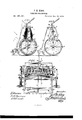
- Figure l is a sectional view of a machine embodying my invention in the line :20 w of Fig. 3.
- Fig. 2 is a side elevation, and
- Fig. 3 is a perspective view, partly broken away to show the interior.
- A represents an axle on which the operating parts are mounted, and is supported on wheels B B, and has a draft-pole
- O is the box in which the seed is carried, and has a bottom, 0, with an inclined board, 0, seated below it.
- the bottom a is perforated with holes 0, the size of which may be regulated by a slideplate, 0, which is held in place by rods 0, and moved to and from the holes 0 by screwrods to.
- D is a head or bar, extending across the box 0, and outward through vertical slots d in the end of the box.
- the head D is pierced with holes, in which the upper end of the force feed-teeth E are secured by a shoulder below the head D, and a pin, 6, which passes through the teeth above the head D.
- F is a shaft, extending across and beyond the box 0, and has a crank, f, on each end, from which a rod, f, extends downward, and connects at its lower end with the lower end of a reciprocating bar, G, the upper end of which by impact with the ground as the machine advances, will give a vertical reciprocating motion to the force feed-teeth E, the lower ends of which pass into the holes 0 in their descent, and force the seeds through, and thus prevent clogging of the seed-passages.
- any'portion of the teeth E may be removed from the head D by removing the pin 6, and those removed may be inserted in their respective holes 0 to close them, as shown by teeth E.
- the shaft I is a rock-shaft, extending across the box (3, and has a crank, 'i, on one end, connected by arod, i, with the end of the head D.
- the shaft I has a series of projecting cleaner-teeth, 2), between and'close to'each feed-tooth E.
- they act as stirrers to keep seeds of certain classes from packing.
- the board 0 serves to spread evenly the seed as it falls thereon, and discharge it evenly in close proximity to the surface of the ground, so that the wind will have but a minimum effect in disturbing their descent.
- J is a bar, provided with harrow-teeth j, and hinged by bars J to the axle A
- K is a similar bar, with teeth It, and is hinged by bars K to the bar J
- L is a cord, attached to, the central part of the bar K, and, passing through an eye, I, on the bar J, is carried upward through an eye, m, in one end of a lever, M, and thence to an attachment, m, on top of the box 0.
- the lever M is fulcrumed on a standard, an, on top of box 0.
- harrow-head J or K may rise and fall independent of the other, their cord connection permitting the same, and at the same time being such that when. drawn on by the lever M, both harrowswill be elevated at once and together, as shown by dotted lines at Fig. 1.
- the attachment of the cord L to the lever M and box 0 is also such that only one-half of the power is required to raise the barrows that would be required if the cord was attached directly to the lever M.
- N is a hook, which may be used to hold the lever M in the position shown by dotted lines at Fig. 1, and the harrows elevatedf The harrows are shown in full lines in the drawings- 2.
- the cleaner-teeth q shaft I, connected by rod a" to the head D,
Landscapes
- Life Sciences & Earth Sciences (AREA)
- Soil Sciences (AREA)
- Environmental Sciences (AREA)
- Engineering & Computer Science (AREA)
- Mechanical Engineering (AREA)
- Soil Working Implements (AREA)
Description
J. M. KING.
SEEDING-MACHINE'S.
No.185,331. Patented Dec.12,1876.
12710012307: Wabwww:
THE GRAPHIC CU-N.Y
UNI E STATES ATET; Qrrioa.
JAMES M. KING, OF SWAN CREEK, ILLINOIS.
IMPRQVEMENT IN SEEDlNG-MACHINES.
Specification forming part of Letters Patent No. l 85,33 1, dated December 12, 1876; application filed September 12, 1876.
To all whom it may concern:
Be it known that I, JAMES M. KING, of Swan Creek, in the county of Warren and State of Illinois, have invented certain new and useful Improvements in Seedingdliachines; and I do hereby declare that the following is a full, clear, and exact description thereof, which will enable others skilled in the art to which it appertains to make and use the same, reference being had to the accompanying drawings, and to the letters of reference marked thereon, which form a part of this specification.
The nature of my invention relates to improvements in seeding-machines of that class used for sowing the small grains broadcast; and the-invention consists in the construction and combination of parts hereinafter fully described, and set forth in the claims.
In the accompanying drawing, Figure l is a sectional view of a machine embodying my invention in the line :20 w of Fig. 3. Fig. 2 is a side elevation, and Fig. 3 is a perspective view, partly broken away to show the interior.
Referring to the parts by letters, A represents an axle on which the operating parts are mounted, and is supported on wheels B B, and has a draft-pole, A. O is the box in which the seed is carried, and has a bottom, 0, with an inclined board, 0, seated below it. The bottom a is perforated with holes 0, the size of which may be regulated by a slideplate, 0, which is held in place by rods 0, and moved to and from the holes 0 by screwrods to. D is a head or bar, extending across the box 0, and outward through vertical slots d in the end of the box. The head D is pierced with holes, in which the upper end of the force feed-teeth E are secured by a shoulder below the head D, and a pin, 6, which passes through the teeth above the head D. F is a shaft, extending across and beyond the box 0, and has a crank, f, on each end, from which a rod, f, extends downward, and connects at its lower end with the lower end of a reciprocating bar, G, the upper end of which by impact with the ground as the machine advances, will give a vertical reciprocating motion to the force feed-teeth E, the lower ends of which pass into the holes 0 in their descent, and force the seeds through, and thus prevent clogging of the seed-passages.
If desired, any'portion of the teeth E may be removed from the head D by removing the pin 6, and those removed may be inserted in their respective holes 0 to close them, as shown by teeth E.
I is a rock-shaft, extending across the box (3, and has a crank, 'i, on one end, connected by arod, i, with the end of the head D. The shaft I has a series of projecting cleaner-teeth, 2), between and'close to'each feed-tooth E. As the teeth E are elevated the teeth 2; are struck downward by their connection with the head D, and thus clear or clean them from all adhering chaff or straw. At the same time they act as stirrers to keep seeds of certain classes from packing. The board 0 serves to spread evenly the seed as it falls thereon, and discharge it evenly in close proximity to the surface of the ground, so that the wind will have but a minimum effect in disturbing their descent.
J is a bar, provided with harrow-teeth j, and hinged by bars J to the axle A, and K is a similar bar, with teeth It, and is hinged by bars K to the bar J. L is a cord, attached to, the central part of the bar K, and, passing through an eye, I, on the bar J, is carried upward through an eye, m, in one end of a lever, M, and thence to an attachment, m, on top of the box 0. The lever M is fulcrumed on a standard, an, on top of box 0.
It will be seen that either harrow-head J or K may rise and fall independent of the other, their cord connection permitting the same, and at the same time being such that when. drawn on by the lever M, both harrowswill be elevated at once and together, as shown by dotted lines at Fig. 1. The attachment of the cord L to the lever M and box 0 is also such that only one-half of the power is required to raise the barrows that would be required if the cord was attached directly to the lever M.
N is a hook, which may be used to hold the lever M in the position shown by dotted lines at Fig. 1, and the harrows elevatedf The harrows are shown in full lines in the drawings- 2. In a seeding-machine, the cleaner-teeth q), shaft I, connected by rod a" to the head D,
combined to operate with the teeth E, holes and for the purpose specified.
, c, and head D, substantially as described,
3. The combination of the harrows J cord L, and lever'M, the cord secured to the barrow-head K, and passing loosely throughan eye, l, in the head J, as described, the harrows having free independent motion when in use, and being simultaneously elevated by the lever when not required for use, substantially as set forth. I
In testimony that I claim the foregoing as my own I aflix my signature in presence of two witnesses.
JAMES M. KING.
Witu esses:
WILLIAM A. WILKINs, THos. MoKEE.
Publications (1)
| Publication Number | Publication Date |
|---|---|
| US185331A true US185331A (en) | 1876-12-12 |
Family
ID=2254736
Family Applications (1)
| Application Number | Title | Priority Date | Filing Date |
|---|---|---|---|
| US185331D Expired - Lifetime US185331A (en) | Improvement in seeding-machines |
Country Status (1)
| Country | Link |
|---|---|
| US (1) | US185331A (en) |
-
0
- US US185331D patent/US185331A/en not_active Expired - Lifetime
Similar Documents
| Publication | Publication Date | Title |
|---|---|---|
| US185331A (en) | Improvement in seeding-machines | |
| US31105A (en) | Improvement in seed-drills | |
| US139732A (en) | Improvement in cotton-planters | |
| US24071A (en) | Improvement in seeding-cultivators | |
| US40937A (en) | Improvement in fanning-mills | |
| US196190A (en) | Improvement in plow attachments for distributing fertilizers | |
| US585211A (en) | Planter | |
| US156416A (en) | Improvement in combined seed-sowers and cultivators | |
| US202026A (en) | Improvement in combined cultivator and corn-planter | |
| US358436A (en) | Expansion double-shovel corn and cotton planter | |
| US324468A (en) | Goodwin | |
| US186826A (en) | Improvement in combined seed-planter, sulky-harrow, and cultivator | |
| US122567A (en) | Improvement in combined seeders, plows, and rollers | |
| US177473A (en) | Improvement in seeding attachments for harrows | |
| US221973A (en) | Improvement in hand corn-planters | |
| US117361A (en) | Improvement in combined seeders and cultivators | |
| US224988A (en) | Combined planter and cultivator | |
| US186275A (en) | Improvement in corn-planters | |
| US53072A (en) | Improvement in combined seeding-machine, roller, and harrow | |
| US173202A (en) | Improvement in combined corn-planters and cultivators | |
| US38313A (en) | Improvement in corn-planters | |
| US49720A (en) | Improvement in seeding-machines | |
| US40365A (en) | Improvement in grain-drills | |
| US216572A (en) | Improvement in grain-drills | |
| US479269A (en) | Corn-planting attachment |