US1853313A - Line grip - Google Patents
Line grip Download PDFInfo
- Publication number
- US1853313A US1853313A US540535A US54053531A US1853313A US 1853313 A US1853313 A US 1853313A US 540535 A US540535 A US 540535A US 54053531 A US54053531 A US 54053531A US 1853313 A US1853313 A US 1853313A
- Authority
- US
- United States
- Prior art keywords
- line
- grip
- jaws
- housing
- anchor
- Prior art date
- Legal status (The legal status is an assumption and is not a legal conclusion. Google has not performed a legal analysis and makes no representation as to the accuracy of the status listed.)
- Expired - Lifetime
Links
- 241000282472 Canis lupus familiaris Species 0.000 description 5
- 210000003813 thumb Anatomy 0.000 description 3
- 239000000463 material Substances 0.000 description 2
- 230000002079 cooperative effect Effects 0.000 description 1
- 238000004519 manufacturing process Methods 0.000 description 1
- 239000002184 metal Substances 0.000 description 1
- 230000003534 oscillatory effect Effects 0.000 description 1
Images
Classifications
-
- F—MECHANICAL ENGINEERING; LIGHTING; HEATING; WEAPONS; BLASTING
- F16—ENGINEERING ELEMENTS AND UNITS; GENERAL MEASURES FOR PRODUCING AND MAINTAINING EFFECTIVE FUNCTIONING OF MACHINES OR INSTALLATIONS; THERMAL INSULATION IN GENERAL
- F16G—BELTS, CABLES, OR ROPES, PREDOMINANTLY USED FOR DRIVING PURPOSES; CHAINS; FITTINGS PREDOMINANTLY USED THEREFOR
- F16G11/00—Means for fastening cables or ropes to one another or to other objects; Caps or sleeves for fixing on cables or ropes
- F16G11/10—Quick-acting fastenings; Clamps holding in one direction only
- F16G11/105—Clamps holding in one direction only
- F16G11/106—Clamps holding in one direction only using a toothed surface
-
- Y—GENERAL TAGGING OF NEW TECHNOLOGICAL DEVELOPMENTS; GENERAL TAGGING OF CROSS-SECTIONAL TECHNOLOGIES SPANNING OVER SEVERAL SECTIONS OF THE IPC; TECHNICAL SUBJECTS COVERED BY FORMER USPC CROSS-REFERENCE ART COLLECTIONS [XRACs] AND DIGESTS
- Y10—TECHNICAL SUBJECTS COVERED BY FORMER USPC
- Y10T—TECHNICAL SUBJECTS COVERED BY FORMER US CLASSIFICATION
- Y10T24/00—Buckles, buttons, clasps, etc.
- Y10T24/39—Cord and rope holders
- Y10T24/3936—Pivoted part
- Y10T24/394—Cam lever
- Y10T24/3951—Dual cam
Definitions
- This invention relates to line grips or holders and refers especially to one adapted for use in the holding of an anchor line for a row boat or the like, though, obviously, may
- the embodiment here illustrated is of such a device for use inholding an anchor line of a row boat and the principal object of the 'invention'is to produce a more practical and eflioient device of this character.
- Another object is to produce such a device capable of adjustment for various sized lines
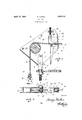
- Figure 1 is a central sectional View dividing the device into two equal halves, with the exception of the upright standard there-,
- Figure 2 is a top plan view of the com pletely assembled device.
- 1 represents a metal bar having a plurality of screw or bolt holes therein for fixing engagement to, for example, the bow of a pleasure boat, such as a row boat or the like.
- a suitable nut 10 is provided below the bar 1 and on the pintle 2 of the support, there being a hole 11 through the pintle below the nut, so that the nut may not be drawn tight, thus permitting of the grip rotating at will while holding to the angular stress of the rope being held, which, in this instance, is the anchor line 12 attached as at 13 to a suitable anchor 14.
- the roller like sheave 15 over which the anchor line 12 is'payed, and thence it extends rearwardly intermediate of the gripping dogs 16 and 17, the former being pivotally mounted intermediate of the side plates 4 and 5 as at 18, and the latter pivotally mounted on the adjustable eyebolt 19.
- the pivotal support of the dog 17 constitutes the pin 20 passing through the eyeof the bolt 19 and also. through both side plates, and for which through passage a vertical slot indicated at 21 is provided in each plate so that the dog 17 may be raised or lowered to accommodate various sized lines.
- the depending :handlelikeportion of the dog 16 is considerably narrower in its. Y .jlower end than-at its upperend so as toprevent binding or frictional contact with the sides in the eventofthe-boat to whichit is applied listing and thereby supporting the grip -in inclined position, resultinginwthe dog116 'operatingas freelyin-inclined position as when upright.
- a line grip of the type described including spaced side plates, a pair of pivotally mountediline grippingsrjaws intermediate of said plates, means for adjusting the s aced relation of said jaws to accommodate ifferentf sized lines and' adjustable pivotally mounted means for supporting said grip.
- a line grip including spaced side plates, spaced line gripping jaws pivotally mounted within said plates, means for adjusting the spaced relation of said-jaws, .and-anadmstable pivotally mounted support forsaid grip.
Landscapes
- Engineering & Computer Science (AREA)
- General Engineering & Computer Science (AREA)
- Mechanical Engineering (AREA)
- Road Paving Machines (AREA)
Description
April 12, 1932. i MATHS 1,853,313
LINE GRIP Filed May 28, 1931 Patented Apr. 12, 1932 UNITED STATES PATENT OFFICE HENRY IMATHIS, OF CLOQUET, MINNESOTA.
LINE GRIP Application filed. May 28, 1931. Serial No. 540,535.
This invention relates to line grips or holders and refers especially to one adapted for use in the holding of an anchor line for a row boat or the like, though, obviously, may
be used for gripping or holding a line under various circumstances.
The embodiment here illustrated is of such a device for use inholding an anchor line of a row boat and the principal object of the 'invention'is to produce a more practical and eflioient device of this character.
Another object is to produce such a device capable of adjustment for various sized lines,
, and also one adjustable to various conditions. 5 of operation. Y
Still other objects and advantages of the novel structure and arrangement of parts will appear in the following description of the invention.
Referring now to the accompanying drawings, forming part of this application, and wherein like reference characters indicate like parts:
Figure 1 is a central sectional View dividing the device into two equal halves, with the exception of the upright standard there-,
for which is shown'inelevation; and
Figure 2 is a top plan view of the com pletely assembled device.
1 represents a metal bar having a plurality of screw or bolt holes therein for fixing engagement to, for example, the bow of a pleasure boat, such as a row boat or the like.
Through the outer end of the bar 1 extends the pintle 2 of the upright support 3, the
latter being fiat upon opposite sides and designed to fit snugly intermediate of the spaced flat walls of the housing of the grip. These walls are illustrated at 4 and 5, they being pivotally attached as at 6 to said upright support or member. Through these side walls are formed a group, preferably of three holes indicated at 7 there being one in this illustration occupied'by the bolt or 5 pin 8 and all of which holes are registrable with the bottom portion of the slot 9 in the upper end of the support or standard 3. This arrangement provides for the adjustment of the housing on the standard; that o is to say the pin 8 may be placed through any one of the three holes desired which would determine the preferred angle for the housing, and when in the desired position may be tightly held by tightening the thumb nut illustrated at 6. A suitable nut 10 is provided below the bar 1 and on the pintle 2 of the support, there being a hole 11 through the pintle below the nut, so that the nut may not be drawn tight, thus permitting of the grip rotating at will while holding to the angular stress of the rope being held, which, in this instance, is the anchor line 12 attached as at 13 to a suitable anchor 14.
Intermediate of the side plates 4 and 5,
above and just slightly forwardly of the upper end of the upright support, is mounted the roller like sheave 15, over which the anchor line 12 is'payed, and thence it extends rearwardly intermediate of the gripping dogs 16 and 17, the former being pivotally mounted intermediate of the side plates 4 and 5 as at 18, and the latter pivotally mounted on the adjustable eyebolt 19. The pivotal support of the dog 17 constitutes the pin 20 passing through the eyeof the bolt 19 and also. through both side plates, and for which through passage a vertical slot indicated at 21 is provided in each plate so that the dog 17 may be raised or lowered to accommodate various sized lines. This raising or lowering is accomplished by the'circular thumb nut 22 extending upon both sides through the side plates so that the same may be readily rotated forvertical adjustment of the bolt 19; said nut being knurled forconvenient manipulation. Both dogs are preferably made of substantially channel shaped material, for strength and convenience in manufacture, and the one16 has an elongated counterbalancing' shank so that the dogis normallyheld in proper gripping position. It is obvious from the above described construction-that forward motion of the line to any material extent is automatically prevented by the cooperative action of the jaws 16 and 17, and that when opposite stress is put upon the line in pulling it inboard, the
jaws instantly free their hold thereupon. If i As illustrative of "the convenience of ithe device, apart from that which is obvious in raising and lowerlng an anchor, attention is directed. to the following: Assuming tan-in dividual, alone in a rowboat, wishes to land upon a sloping shore or beach, th1s device'is particularly convenient in .that he may. ap.
proach the shore, advance to the bow of the boat, heave 'the anchor ashore; then .return to the stern of theboat which willinaterially reduce the draft at the how, when, by pulling onthe freeend of the anchor line through the :;;grip,'.hemay readily pullthe boat well up onto the shore. While this is but one illustration of the convenienceofsuch a .devlce many others may resultfrom its use under various circumstances.
It is'to be-notedthat the vertical corrugations or .knurling of the thumb nut have'a double-function which .includes the bettergrip for. turning same, as well as the engagement with the edges of the holes-throughthe .;plates 4 and 5, .which preventsaccidentalz turning. of same, as the; nutis comparatively I loose in said holes.
Also the depending :handlelikeportion of the dog 16 is considerably narrower in its. Y .jlower end than-at its upperend so as toprevent binding or frictional contact with the sides in the eventofthe-boat to whichit is applied listing and thereby supporting the grip -in inclined position, resultinginwthe dog116 'operatingas freelyin-inclined position as when upright.
Having :thus described my inventi on, what I claimanddesiretosecure by Letters Pat-i cut, is:
1. A linegr-ip of- .thetype described .comprising a housing pivotal-1y carried upon a pivotalsupport,-a roller within the housing-v forwardly of the pivotal support thereof,
and a pair ofpivoted gripping jaws upon the oppositexside of the I pivotal support,
whereby a line-may be passed over the roller and betweenthe jaws, and be-manipulated remote from the grip atiany desired-angler 2. Aline grippf the. type described .com
-" *prising a housing pivotally carried upon a pivotal support, said housing being, open.
throughout its entire marginal edges, a roller within the housing forwardly of the pivotal support,!a pair of aws'withinthe housing p. 'rea-rwardly 'of theasupport, whereby a line may be passed over the roller and between the jaws and manipulated remote fromthe grip at..any -desired angle.
3.1 A line-grip of'the type described inplates, two line gripping a-ws pivotally mounted between the plates, the uppermost one being vertically adjustable to accommodate diiferent sized lines, and both jaws having free oscillatory motion.
4. A line grip of the type described including spaced side plates, a pair of pivotally mountediline grippingsrjaws intermediate of said plates, means for adjusting the s aced relation of said jaws to accommodate ifferentf sized lines and' adjustable pivotally mounted means for supporting said grip.
5. A line grip including spaced side plates, spaced line gripping jaws pivotally mounted within said plates, means for adjusting the spaced relation of said-jaws, .and-anadmstable pivotally mounted support forsaid grip. In testimony whereof I affix mvsignaturea- HENRY. MATHIS.
'cludingaroller-intermediate of two spaced" I
Priority Applications (1)
| Application Number | Priority Date | Filing Date | Title |
|---|---|---|---|
| US540535A US1853313A (en) | 1931-05-28 | 1931-05-28 | Line grip |
Applications Claiming Priority (1)
| Application Number | Priority Date | Filing Date | Title |
|---|---|---|---|
| US540535A US1853313A (en) | 1931-05-28 | 1931-05-28 | Line grip |
Publications (1)
| Publication Number | Publication Date |
|---|---|
| US1853313A true US1853313A (en) | 1932-04-12 |
Family
ID=24155865
Family Applications (1)
| Application Number | Title | Priority Date | Filing Date |
|---|---|---|---|
| US540535A Expired - Lifetime US1853313A (en) | 1931-05-28 | 1931-05-28 | Line grip |
Country Status (1)
| Country | Link |
|---|---|
| US (1) | US1853313A (en) |
Cited By (5)
| Publication number | Priority date | Publication date | Assignee | Title |
|---|---|---|---|---|
| US2470316A (en) * | 1947-09-22 | 1949-05-17 | Miller John Zin | Rope holder |
| US2547370A (en) * | 1948-11-02 | 1951-04-03 | Charles A Boyer | Rope lock |
| US20070151999A1 (en) * | 2004-04-16 | 2007-07-05 | Stephen Thompson | Sling Clip and Attachment |
| US8857680B1 (en) * | 2004-04-16 | 2014-10-14 | Stephen T. Thompson | Biomechanically improved sling and attachments |
| US10634451B1 (en) | 2017-11-08 | 2020-04-28 | Stephen T. Thompson | Sling clips and attachment |
-
1931
- 1931-05-28 US US540535A patent/US1853313A/en not_active Expired - Lifetime
Cited By (6)
| Publication number | Priority date | Publication date | Assignee | Title |
|---|---|---|---|---|
| US2470316A (en) * | 1947-09-22 | 1949-05-17 | Miller John Zin | Rope holder |
| US2547370A (en) * | 1948-11-02 | 1951-04-03 | Charles A Boyer | Rope lock |
| US20070151999A1 (en) * | 2004-04-16 | 2007-07-05 | Stephen Thompson | Sling Clip and Attachment |
| US7950551B2 (en) * | 2004-04-16 | 2011-05-31 | Thompson Stephen T | Sling clip and attachment |
| US8857680B1 (en) * | 2004-04-16 | 2014-10-14 | Stephen T. Thompson | Biomechanically improved sling and attachments |
| US10634451B1 (en) | 2017-11-08 | 2020-04-28 | Stephen T. Thompson | Sling clips and attachment |
Similar Documents
| Publication | Publication Date | Title |
|---|---|---|
| US2311823A (en) | Fishing rod holder | |
| US2811127A (en) | Mooring hook | |
| DE2430996A1 (en) | MOORING BUOY | |
| US1987842A (en) | Fishing pole support | |
| US1853313A (en) | Line grip | |
| US2541146A (en) | Fish pole holder | |
| US2343086A (en) | Safety suspension device | |
| US2872889A (en) | Water ski tow device | |
| US2907238A (en) | Vice for use with a sawhorse | |
| US2081383A (en) | Pipe wrench | |
| US2130650A (en) | Device for holding fishing rods or poles | |
| US1283511A (en) | Fishing-rod holder. | |
| US307986A (en) | porritt | |
| US2972325A (en) | Water ski tow rope guide | |
| US2527402A (en) | Line slack adjuster | |
| US3047262A (en) | Holder for fishing rods and the like | |
| US1757548A (en) | Vise | |
| US1675930A (en) | Anchoring device for boats | |
| DE564003C (en) | Handheld vacuum cleaner | |
| DE633102C (en) | Hook for tensioning clotheslines or the like with a clamping slot and holding legs | |
| US2995763A (en) | Oar stabilizer | |
| US786045A (en) | Rod-holder. | |
| US2671232A (en) | Oar hanger | |
| DE621416C (en) | Violin holder adjustable in height and direction | |
| US4027989A (en) | Chain anchor |