US1853311A - Door latch mechanism - Google Patents
Door latch mechanism Download PDFInfo
- Publication number
- US1853311A US1853311A US31114928A US1853311A US 1853311 A US1853311 A US 1853311A US 31114928 A US31114928 A US 31114928A US 1853311 A US1853311 A US 1853311A
- Authority
- US
- United States
- Prior art keywords
- roll
- latch
- bolt
- dog
- door
- Prior art date
- Legal status (The legal status is an assumption and is not a legal conclusion. Google has not performed a legal analysis and makes no representation as to the accuracy of the status listed.)
- Expired - Lifetime
Links
- 241000282320 Panthera leo Species 0.000 description 2
- 238000010276 construction Methods 0.000 description 2
- 230000000694 effects Effects 0.000 description 2
- 230000007935 neutral effect Effects 0.000 description 2
- 238000009877 rendering Methods 0.000 description 2
- RZVAJINKPMORJF-UHFFFAOYSA-N Acetaminophen Chemical group CC(=O)NC1=CC=C(O)C=C1 RZVAJINKPMORJF-UHFFFAOYSA-N 0.000 description 1
- 101100310856 Drosophila melanogaster spri gene Proteins 0.000 description 1
- 235000012489 doughnuts Nutrition 0.000 description 1
- 230000009977 dual effect Effects 0.000 description 1
Images
Classifications
-
- E—FIXED CONSTRUCTIONS
- E05—LOCKS; KEYS; WINDOW OR DOOR FITTINGS; SAFES
- E05B—LOCKS; ACCESSORIES THEREFOR; HANDCUFFS
- E05B85/00—Details of vehicle locks not provided for in groups E05B77/00 - E05B83/00
- E05B85/20—Bolts or detents
- E05B85/22—Rectilinearly moving bolts
-
- Y—GENERAL TAGGING OF NEW TECHNOLOGICAL DEVELOPMENTS; GENERAL TAGGING OF CROSS-SECTIONAL TECHNOLOGIES SPANNING OVER SEVERAL SECTIONS OF THE IPC; TECHNICAL SUBJECTS COVERED BY FORMER USPC CROSS-REFERENCE ART COLLECTIONS [XRACs] AND DIGESTS
- Y10—TECHNICAL SUBJECTS COVERED BY FORMER USPC
- Y10S—TECHNICAL SUBJECTS COVERED BY FORMER USPC CROSS-REFERENCE ART COLLECTIONS [XRACs] AND DIGESTS
- Y10S292/00—Closure fasteners
- Y10S292/24—Dogging mechanism from inside operating means
-
- Y—GENERAL TAGGING OF NEW TECHNOLOGICAL DEVELOPMENTS; GENERAL TAGGING OF CROSS-SECTIONAL TECHNOLOGIES SPANNING OVER SEVERAL SECTIONS OF THE IPC; TECHNICAL SUBJECTS COVERED BY FORMER USPC CROSS-REFERENCE ART COLLECTIONS [XRACs] AND DIGESTS
- Y10—TECHNICAL SUBJECTS COVERED BY FORMER USPC
- Y10T—TECHNICAL SUBJECTS COVERED BY FORMER US CLASSIFICATION
- Y10T292/00—Closure fasteners
- Y10T292/08—Bolts
- Y10T292/096—Sliding
- Y10T292/0969—Spring projected
- Y10T292/097—Operating means
- Y10T292/0974—Link and lever
Definitions
- This invention relates generally to remote 1Q and operablefrom the outer-side (at door control mechanism'for vehicle doors and the to effect the retraction of the yoke 4 and latch like, and consists of certain novel features; of bolt. 15 isan auxiliary caseplate adapted to construction,-combinations and arrangements be securedto the inner side of the door 'at a of parts that will be hereinafter more fully point .remotefrom the case platell. vJ16 is a i described and particularly pointed out in the appended claims.
- auxiliary case plate, 17 is a lever rigidly mounted on the stub shaft, 18 is a link pivotallyconnected'at one
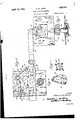
- the yoke, and 20 is a, handle carried by the Figure2 is'a view similiar to Figure 1 but stub shaft 16 and operable from the inner with the roll-"back rendered inoperative by 1 side ofthedoor toactuate the lever 17 and the dog;
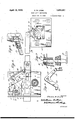
- Figure 3 is a vertical sectional view latch bolt independently of the roll-back 9.
- Figure 4 is a detail perspective view of and adapted to be actuated by thelinkto renthe dog; p vder the roll-back inoperative for retracting '20
- Figure 5 is a detail perspective view of the the bolt.
- the hub 10-- of the roll-back 9 Figure 6 is'a detail perspective view of the is in the form of a hollow rivet and is proupstanding lever of.
- the remote 'control 7 vided at its opposite ends withlateral flanges mechanism and showing the recess therein 10' andlO that overlapthe roll-back 9 and for receiving a ortion of the detent spring; case plate 1.1
- the dog 21- is substantially V- Figure7 is a' ragmentary sectional view of shaped in form with the ivot22 therefor the latch case plate and roll-back rivet.
- a t e apexthereof and wit the arms 23 and Figure 8 is a detail perspective view of a 24 thereof adjacent to the. roll-back-9 and portion of the dog and link mechanism. link. 18..
- the forward arm. 23 has Referring.
- 1 is a latch a forwardly and upwardly projecting shoul- 7 case plate ada ted to be secured to the inner der or extension 25 engageable with a simiside of a vehicle door adjacent to the, free 'lar shoulder or projection 26 of the roll-back edge thereof and having a lateral flange'2 at i), while the. rear arm 24 has a lateral. pre- 1 its forward edge attachable to the free edge ection or flange 27 engageable with the foras of the door.
- 3 is a reciprocating latch bolt ward end of the link 18. Normally the u.
- the arm mally maintaining the yoke and latch bolt in 33 of the spring. may be anchored to the case v g; advanced position.
- 9 is a roll-back having a vplate 1 at a point between the arms 23 and hub 10, provided with lateral flanges 10 and 24, however, when 1t is connected to the 10'', and having an arm 11 engageable with an roll-back 9 as shown 1t normally maintains arm 12 of the yoke.
- 13 is a handle havinga the roll-back agalnst the lateral flange 2 of i shank 14 non-rotatably received in the rivet the case plate 1 when the yoke is retracted an,
- the latch bolt 3 may be retracted by 0 remote control mechanism upon v side of the door or by the roll-back the outside of the door without dis the dog 21.
- the lever 17 is" manually by manipulation of the trol yoh 4 rearwardly and upon release of the nlide handle 20 the helical. spring 6 will parts to resume normal position; when it is desired to render the 9 inoperative,the lever 17 is swung v by the inside handle 20 so asto cau'the 18 to push the rear arm 24 d the dog forwardly and thereby cause the i 25 of the forward. in: 23
- a ring ll'betweenthelever 1 an auxiliary case plateand having a detent 34 enw1th-amcess35mthelever17is tgodstachfily lever 17, link in orwa o position the of the spri
- a 18 will bemovedrear-- wardlyaoaatopermit um thespring30 to auto- Iltleally' return h I a d I ti it mg): escnp on 1 dog to normal posiemu thatte ispositively Iorei-byrenotscomtrolmechamaminto position with respect to the roll- I bntitiaantomaticallyreleasedbythe llapriqwwhen
- the rivet forof roll backhub 10 is also animportanthatnraasitservesthe dual funcdapivotandattachingmeansforthe such a construction liltlfi mulcoverp 'ycooperatin wi plate or an portin the ro -back wit entire y.
- the latch asembly may be M J ifiataalled at a comparat a it is to 0 rate. i a beliznvzd that the foredamp tion, naturean a vantages invention will be readily apparent, I donut dire to limit myself to what is hereinallown and that such changes may M to whenrdesired as fall withthe scope of. what is claimed.
- yoke connected to the bolt and constituting rearward extension thereof, a roll-back engageable with the yoke and operable from the outer side of a door to retract the bolt, remote control means operable from the inner a door to retract the bolt and including a sliding link connected to and constituting a rearward extension of said yoke a pivotal] mounted element between the link and to back and movable bythe linkintotheg ztil: oi the roll-back to revent the same moving to retract bolt, and yieldable means to connected to the roll-back and element normally maintaining both the element and roll-back in neutral positions.
- a latch bolt operable to retract the bolt, a dog-for rendering' the roll-back inoperative, and a 'eldab connection between said dog rollback and operable automatically to restore eitherorboth ofsaid parts tonormal position' after they have been moved.
- a latch bolt means operable to retract the bolt includ' aroll-back, means for rendering the roll-bat inoperative and a yieldable connection between the two means aforesaid operable automatically to restore eitherofaaidmeanstonormalposition after they have been moved.
Landscapes
- Lock And Its Accessories (AREA)
Description
April 19324 ca. LOWE 1,853,311"
, noon mwcqmmmursxq 2 Sheets-Shae 1 Filed 001;..8, -19 2s 71422 as flaw-e ATTORNEYS April 12,1932. 1 c, ow]; 1,853,311
DOOR LATCH MECHANISM Filed Oct. 8, 1928 2 Sheets-Sheet 2 INVENTOR /mirdas 3. Iowa BY W ' fi m v Ma I Patented Apr. 12, 1932 UNITED STATES" PATENT oFFic I v cmaLEs 2B. LowE,"oE DETROlIT, MICHIGAN, ASSIGNOR To rnanoesmurnm a mv FACTUBING COMPANY, or DETROIT, MICHIGAN, a-conrona'r'ron or moment noon LATCH mcmmsm Y i I application iilcd October 8, 192a Serial m). 311,149. This invention relates generally to remote 1Q and operablefrom the outer-side (at door control mechanism'for vehicle doors and the to effect the retraction of the yoke 4 and latch like, and consists of certain novel features; of bolt. 15 isan auxiliary caseplate adapted to construction,-combinations and arrangements be securedto the inner side of the door 'at a of parts that will be hereinafter more fully point .remotefrom the case platell. vJ16 is a i described and particularly pointed out in the appended claims. In the accompanyingdrawings-' stub shaft j ournaled in the; auxiliary case plate, 17 is a lever rigidly mounted on the stub shaft, 18 is a link pivotallyconnected'at one I Figure l is a side elevation of a latch mech; end to the lever 17 and having a slotted colianism embodying=myinvention and showing nection at its other end with the arm 19 of w, the parts thereof in normal position; the yoke, and 20 is a, handle carried by the Figure2 is'a view similiar to Figure 1 but stub shaft 16 and operable from the inner with the roll-"back rendered inoperative by 1 side ofthedoor toactuate the lever 17 and the dog; j link 18 to effect the retraction of the yoke and 15f Figure 3 is a vertical sectional view latch bolt independently of the roll-back 9. 55 through the auxiliary case plate and associ 21 is a dog swingingly mounted on the case ated parts I I plate' l-between the link 18 and roll-back 9 1 Figure 4 isa detail perspective view of and adapted to be actuated by thelinkto renthe dog; p vder the roll-back inoperative for retracting '20 Figure 5 is a detail perspective view of the the bolt. l I, 70 detent spring; Asshown the hub 10-- of the roll-back 9 Figure 6 is'a detail perspective view of the is in the form of a hollow rivet and is proupstanding lever of. the remote 'control 7 vided at its opposite ends withlateral flanges mechanism and showing the recess therein 10' andlO that overlapthe roll-back 9 and for receiving a ortion of the detent spring; case plate 1.1 The dog 21- is substantially V- Figure7 is a' ragmentary sectional view of shaped in form with the ivot22 therefor the latch case plate and roll-back rivet. a t e apexthereof and wit the arms 23 and Figure 8 is a detail perspective view of a 24 thereof adjacent to the. roll-back-9 and portion of the dog and link mechanism. link. 18.. Preferably, the forward arm. 23 has Referring. now to the drawings, 1 is a latch a forwardly and upwardly projecting shoul- 7 case plate ada ted to be secured to the inner der or extension 25 engageable with a simiside of a vehicle door adjacent to the, free 'lar shoulder or projection 26 of the roll-back edge thereof and having a lateral flange'2 at i), while the. rear arm 24 has a lateral. pre- 1 its forward edge attachable to the free edge ection or flange 27 engageable with the foras of the door. 3 is a reciprocating latch bolt ward end of the link 18. Normally the u. that is movable through an opening in the shoulder 25 is'held disengaged from the roll flan e2for en agement with a suitable keepback shoulder 26 and the lateral flange 27 er not shown and having a portion slid- 1s held agalnst the link 18. This is accomably mounted on the case plate. 4 is a yoke, plished by the prov slon of a wire spring 30 I to slidably mounted on the case plate and hav. which preferably has an intermediate poro a ing one arm 5 thereof rigidly secured to the tion 31 wound about the dog pivot 22 and bolt 3. 6 is a helical spring anchored on has diverging arm portions 32 and 33 respecthe case plate and having one arm 7 thereof tively terminally connected to the dog arm abutting the rear end of the bolt 3 and nor- 24 and to theroll-back 9. is If desired the arm mally maintaining the yoke and latch bolt in 33 of the spring. may be anchored to the case v g; advanced position. 9 is a roll-back having a vplate 1 at a point between the arms 23 and hub 10, provided with lateral flanges 10 and 24, however, when 1t is connected to the 10'', and having an arm 11 engageable with an roll-back 9 as shown 1t normally maintains arm 12 of the yoke. 13 is a handle havinga the roll-back agalnst the lateral flange 2 of i shank 14 non-rotatably received in the rivet the case plate 1 when the yoke is retracted an,
by the remote control mechanism and will the outer handle 13 and shank 14 in proper horizontal osition and will also prevent the roll-back from rattling.
Inuae the latch bolt 3 may be retracted by 0 remote control mechanism upon v side of the door or by the roll-back the outside of the door without dis the dog 21. When the remote conis utilized the lever 17 is" manually by manipulation of the trol yoh 4 rearwardly and upon release of the nlide handle 20 the helical. spring 6 will parts to resume normal position; when it is desired to render the 9 inoperative,the lever 17 is swung v by the inside handle 20 so asto cau'the 18 to push the rear arm 24 d the dog forwardly and thereby cause the i 25 of the forward. in: 23
opei'atilvel' enga wit t e r0 D ue to a: slotted connection link 18 and the oke 4 this movement of t e link may moving the yoke I Preferably a ring ll'betweenthelever 1 an auxiliary case plateand having a detent 34 enw1th-amcess35mthelever17is tgodstachfily lever 17, link in orwa o position the of the spri When 17 is returned to neutral or upw manipulation of the inhandle, a 18 will bemovedrear-- wardlyaoaatopermit um thespring30 to auto- Iltleally' return h I a d I ti it mg): escnp on 1 dog to normal posiemu thatte ispositively Iorei-byrenotscomtrolmechamaminto position with respect to the roll- I bntitiaantomaticallyreleasedbythe llapriqwwhentheremotecontrolpartsare returladtonormal position. The rivet forof roll backhub 10 is also animportanthatnraasitservesthe dual funcdapivotandattachingmeansforthe such a construction liltlfi mulcoverp 'ycooperatin wi plate or an portin the ro -back wit entire y. It will also that the latch asembly may be M J ifiataalled at a comparat a it is to 0 rate. i a beliznvzd that the foredamp tion, naturean a vantages invention will be readily apparent, I donut dire to limit myself to what is hereinallown and that such changes may M to whenrdesired as fall withthe scope of. what is claimed.
Whatl l c am as my invention is: L
tivel a door latch, a latch bolt, a sliding n A 20soastomove thelink 18 and" LOGO, 1-
yoke connected to the bolt and constituting rearward extension thereof, a roll-back engageable with the yoke and operable from the outer side of a door to retract the bolt, remote control means operable from the inner a door to retract the bolt and including a sliding link connected to and constituting a rearward extension of said yoke a pivotal] mounted element between the link and to back and movable bythe linkintotheg ztil: oi the roll-back to revent the same moving to retract bolt, and yieldable means to connected to the roll-back and element normally maintaining both the element and roll-back in neutral positions.
2. In a door latch, a latch bolt, a roll-back operable to retract the bolt, a dog-for rendering' the roll-back inoperative, and a 'eldab connection between said dog rollback and operable automatically to restore eitherorboth ofsaid parts tonormal position' after they have been moved.
8. In a door latch, a latch bolt, means operable to retract the bolt includ' aroll-back, means for rendering the roll-bat inoperative and a yieldable connection between the two means aforesaid operable automatically to restore eitherofaaidmeanstonormalposition after they have been moved.
, 4. In a dm'latch a latch bolt, a rollback operable to actthebolt,apivot element, a doimounted on aaid'pivot element and having 'ver' armportiongoneofaaidarm portions ing engageable with the rollback torenderthesame' rative,l.nda Liam} t e on 1h: pivot element vergm arm portions 'v ,mmmh. mm..- mg
and to the rollback.
In testimony whereof I afix in side of 1.
Priority Applications (1)
| Application Number | Priority Date | Filing Date | Title |
|---|---|---|---|
| US31114928 US1853311A (en) | 1928-10-08 | 1928-10-08 | Door latch mechanism |
Applications Claiming Priority (1)
| Application Number | Priority Date | Filing Date | Title |
|---|---|---|---|
| US31114928 US1853311A (en) | 1928-10-08 | 1928-10-08 | Door latch mechanism |
Publications (1)
| Publication Number | Publication Date |
|---|---|
| US1853311A true US1853311A (en) | 1932-04-12 |
Family
ID=23205630
Family Applications (1)
| Application Number | Title | Priority Date | Filing Date |
|---|---|---|---|
| US31114928 Expired - Lifetime US1853311A (en) | 1928-10-08 | 1928-10-08 | Door latch mechanism |
Country Status (1)
| Country | Link |
|---|---|
| US (1) | US1853311A (en) |
-
1928
- 1928-10-08 US US31114928 patent/US1853311A/en not_active Expired - Lifetime
Similar Documents
| Publication | Publication Date | Title |
|---|---|---|
| US2896990A (en) | Vehicle closure latch | |
| US3788687A (en) | Safety exit latch bolt retainer | |
| US2793061A (en) | Hood latch structure | |
| US1909210A (en) | Doorlatch | |
| US2075495A (en) | Door lock | |
| US1853311A (en) | Door latch mechanism | |
| US3394957A (en) | Closure latch | |
| US2006129A (en) | Automobile doorlatch operator | |
| US2039873A (en) | Coach latch | |
| US2281317A (en) | Lock | |
| US2222411A (en) | Door latch mechanism | |
| US4421350A (en) | Foot-operated, latch releasing mechanism for automobile doors | |
| US2142456A (en) | Coach lock | |
| US1807775A (en) | devereaux | |
| US2246794A (en) | Automobile hood latching structure | |
| US2315815A (en) | Vehicle door latch | |
| US3173715A (en) | Door lock | |
| US1663245A (en) | Door latch | |
| US1939542A (en) | Doorlatch construction | |
| US3206239A (en) | Auxiliary latch mechanism for vehicle door | |
| US1621497A (en) | Boor latch | |
| US2994451A (en) | Support for a hinged closure | |
| US2106954A (en) | Door latch and lock structure | |
| US1876655A (en) | Door latch | |
| US1904970A (en) | Doorlatch |