US1853300A - Universal joint - Google Patents
Universal joint Download PDFInfo
- Publication number
- US1853300A US1853300A US204490A US20449027A US1853300A US 1853300 A US1853300 A US 1853300A US 204490 A US204490 A US 204490A US 20449027 A US20449027 A US 20449027A US 1853300 A US1853300 A US 1853300A
- Authority
- US
- United States
- Prior art keywords
- arm
- sleeve
- bearing
- cross
- arms
- Prior art date
- Legal status (The legal status is an assumption and is not a legal conclusion. Google has not performed a legal analysis and makes no representation as to the accuracy of the status listed.)
- Expired - Lifetime
Links
- 238000010276 construction Methods 0.000 description 4
- 210000002105 tongue Anatomy 0.000 description 2
- 102000007469 Actins Human genes 0.000 description 1
- 108010085238 Actins Proteins 0.000 description 1
- 101000821829 Homo sapiens Solute carrier family 22 member 17 Proteins 0.000 description 1
- 235000011464 Pachycereus pringlei Nutrition 0.000 description 1
- 240000006939 Pachycereus weberi Species 0.000 description 1
- 235000011466 Pachycereus weberi Nutrition 0.000 description 1
- 102100021542 Solute carrier family 22 member 17 Human genes 0.000 description 1
- 150000001768 cations Chemical class 0.000 description 1
- 238000006073 displacement reaction Methods 0.000 description 1
- 241000894007 species Species 0.000 description 1
Images
Classifications
-
- F—MECHANICAL ENGINEERING; LIGHTING; HEATING; WEAPONS; BLASTING
- F16—ENGINEERING ELEMENTS AND UNITS; GENERAL MEASURES FOR PRODUCING AND MAINTAINING EFFECTIVE FUNCTIONING OF MACHINES OR INSTALLATIONS; THERMAL INSULATION IN GENERAL
- F16D—COUPLINGS FOR TRANSMITTING ROTATION; CLUTCHES; BRAKES
- F16D3/00—Yielding couplings, i.e. with means permitting movement between the connected parts during the drive
- F16D3/16—Universal joints in which flexibility is produced by means of pivots or sliding or rolling connecting parts
- F16D3/26—Hooke's joints or other joints with an equivalent intermediate member to which each coupling part is pivotally or slidably connected
- F16D3/38—Hooke's joints or other joints with an equivalent intermediate member to which each coupling part is pivotally or slidably connected with a single intermediate member with trunnions or bearings arranged on two axes perpendicular to one another
- F16D3/40—Hooke's joints or other joints with an equivalent intermediate member to which each coupling part is pivotally or slidably connected with a single intermediate member with trunnions or bearings arranged on two axes perpendicular to one another with intermediate member provided with two pairs of outwardly-directed trunnions on intersecting axes
Definitions
- One of the primary obj ects of my invention is to provide a simple and economical joint as well as one which may be easily assembled and adjusted.
- a still further object is to 6 provide a simple and eificient means for providing and adjusting an end thrust element of the joint.
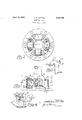
- Fig. 1 is a plan view, with certain parts broken away, illustrating a constructlon embodying my invention.
- Fig. 2 is a view taken substantially on hne 2-2 of Fig. 1.
- Fig. 3 is a perspective of the bearing fastening means employed in my device.
- Fi 4 is a detailed sectional vlew showing a mo ified form of the bearing fastening device.
- a joint comprising yokes 5 and 6, the outer ends of the arms of which are open to receive cross arms 7 which extend from the central portion 8 of a conventional cardon cross.
- Each of the arms 7 is provided With a bearing sleeve 9 in its end opening having a closed end adapted to form an end thrust bearing as at 10 and also providedv with a slot or depression 11 in the outer surface of such closed end.
- each yoke arm a fastener element having a tongue 12 which is 'w adapted to be engaged in a groove 13 of its yoke arm, an intermediate curved ortion 14 which is adapted to bear against t e endof its adj acent sleeve 9 at the bottom of the slot 11, and a cap portion 15 at substantially right angles thereto which is adapted to engage over the top 'of its sleeve 9 'and to be secured to its yoke 'arm by screws 16 extending through the openings 17, thereby exerting a radial pressure' on the co-operating sleeve tending to clampt it against movement.
- the cap prtion 15 of the fastening device normally tends to be positioned outwardly from its final position because of the curved portion 14 engaging the bot-tom of the slot 11 so that in order to engage the screws 16 it is necessary to force the top of the fastening device inwardly toward the center of the joint, thereby placing the central portion 14 under tension and holding the end of each sleeve 9 pressed against the end of its cross arm 7
- the central portion 14 of each device is slightly less in width than the co- Operating slot 11 on the sleeve in which it is received so as to prevent turning of the sleeve and also prevent the tongues 12 from being dislocated.
- each sleeve may be hardened or a hardened washer may be inserted therein for the purpose of taking the wear of the end thrust against the same.
- the fastening device is composed solely of a cap 19, no end bearing fas'tening element being shown.
- the clamping action of the cap against the sleeve is relied upon to hold its sleeve against longitudinal displacement without the assistance of an end piece for accomplishing that purose.
- a universal 'joint comprising a pair of yokes and a cross, each yoke arm having a cross arm therein, a sleeve'on each cross arm, an end thrust bearing for the arm in each sleeve and a cap secured to each yoke armv bearing on its sleeve to hold the sleeve against movement, each said cap having a portion extended over the end of its adj acent sleeve.
- a universal joint comprising a pair of yokes and a cross, each yoke arm having a cross arm therein, a sleeve on each cross arm, an end thrust bearing for the arm in each sleeve and a cap secured to each yoke arm bearing on its sleeve to hold the sleeve against movement, each said cap having a portion extended over the end of its adjacent sleeve and into a portion of the yoke.
- a universal joint comprising a pair of yokes and a cross, each yoke arm having a cross arm therein, a sleeve on each cross arm, an end thrust bearing for the arm in each sleeve and a cap secured to each yoke arm bearing on its sleeve to hold the sleeve against movement,I each said cap having a portion extended over the end of its adj acent sleeve and into a portion of the yoke, said portion being held against the sleeve under spring tensionwhen the cap is secured in place.
- a universal joint comprising a pair of yokes and a cross, the arms of the cross having bearings, one in each of the yoke arms, an end thrust bearing for each cross arm and a cap secured to each yoke arm holding the cross arm and its end thrust bearing in place, each said cap having a portion extended .over the end of its adj acent arm.
- a universal joint comprising a pair of yokes and a cross, the arms of the cross having bearings, one in each of the yoke arms, an
- each yoke arm holding the cross arm and its end thrust bearing in place, each said cap having a portion extended over 'the end of its adj acent arm, and into a portion of the yoke.
- a universal joint comprising a pair of yokes and a cross, the arms of the cross having bearings, one in each of the yoke arms, an end thrust bearing for each cross arm and a cap secured to each yoke arm holdfing the cross arm and its end thrust bearing in lace, each said cap having a portion extende over the end of its adj acent arm and into a portion of the yoke, said portion being held against the bearing member under spring tension when the cap is secured in place.
- a universal joint having a bearing member, an arm oscillatable in said bearing member, and an end thrust bearing for taking thrust from said arm including a de- .formed metallic abutment member yieldingly exerting pressure by its inherent tension against said arm.
- a universal joint comprising a pair of yokes and a cross member, the arms of the cross bearing in the arms of the yokes, end thrust bearings for taking thrust' from the arms including spring tensioned pieces excrting pressure against the ends of the arms.
- a universal joint comprising a pair of yokes and a cross member, the arms of the cross/bearing in the arms of the yokes, endl thrust bearings for taking thrust from the arms including spring tensioned pieces exerting pressure against the ends of said arms, said pieces being inserted in grooves provided in the yokes.
- a universal joint comprising a pair of yokes having bearing members associated therewith, slots in at least some of said yokes and means cooperatively engaged with said slots and interposed between the slots and the ends of said bearing members for taking end thrust from said bearing members.
- a universal joint having bearing members and supports therefor, slots in at least some of said supports and means cooperatively engaged with said slots and interposed between the slots and the ends of said bearings for taking end thrust from said bearing members.
- a universal joint comprising a pair of yokes having bearing members associated therewith, slots in at least some of said yokes and means cooperatively engaged With said slots and interposed between the slots and the ends of said bearing members for taking end thrust from said bearing members, said means being in the nature of a strip for each slot extended into the sl'ot and acting as a hacking plate for an adjacent bearing member.
Landscapes
- Engineering & Computer Science (AREA)
- General Engineering & Computer Science (AREA)
- Mechanical Engineering (AREA)
- Pivots And Pivotal Connections (AREA)
Description
UNIVERSAL JOINT Filed July l9, 1927 12. 5 '61% /1- 'lx a' [NVENTOR 4 I MTTORNEY Patented Apr. 12;v 1932 I CHARLES D. CU'I'TING, OF DE'I'BOIT, MICHIGAN PATENT oFFlcE UNIVERSAL JOINT 'Application flled July 9, 1927. Serial No. 204,490.
' One of the primary obj ects of my invention is to provide a simple and economical joint as well as one which may be easily assembled and adjusted. A still further object is to 6 provide a simple and eificient means for providing and adjusting an end thrust element of the joint.
With the above and other objects in view, my invention consists in the arrangement, combination and construction of the various parts of m improved device, as' described 1n the speci cation, claimed in my claims and shown in the accompanying drawings, in which:
Fig. 1 is a plan view, with certain parts broken away, illustrating a constructlon embodying my invention.
Fig. 2 is a view taken substantially on hne 2-2 of Fig. 1.
Fig. 3 is a perspective of the bearing fastening means employed in my device.
Fi 4 is a detailed sectional vlew showing a mo ified form of the bearing fastening device.
' I have shown a joint comprising yokes 5 and 6, the outer ends of the arms of which are open to receive cross arms 7 which extend from the central portion 8 of a conventional cardon cross. Each of the arms 7 is provided With a bearing sleeve 9 in its end opening having a closed end adapted to form an end thrust bearing as at 10 and also providedv with a slot or depression 11 in the outer surface of such closed end. For the purpose of securing the arms and their sleeves in the yokes as well as for the purpose of forcing the ends of the sleeves against the ends of the arms, I have provided for each yoke arm a fastener element having a tongue 12 which is 'w adapted to be engaged in a groove 13 of its yoke arm, an intermediate curved ortion 14 which is adapted to bear against t e endof its adj acent sleeve 9 at the bottom of the slot 11, and a cap portion 15 at substantially right angles thereto which is adapted to engage over the top 'of its sleeve 9 'and to be secured to its yoke 'arm by screws 16 extending through the openings 17, thereby exerting a radial pressure' on the co-operating sleeve tending to clampt it against movement. It
will be noted by particular reference to Fig. 1 that when assembling, the cap prtion 15 of the fastening device normally tends to be positioned outwardly from its final position because of the curved portion 14 engaging the bot-tom of the slot 11 so that in order to engage the screws 16 it is necessary to force the top of the fastening device inwardly toward the center of the joint, thereby placing the central portion 14 under tension and holding the end of each sleeve 9 pressed against the end of its cross arm 7 The central portion 14 of each device is slightly less in width than the co- Operating slot 11 on the sleeve in which it is received so as to prevent turning of the sleeve and also prevent the tongues 12 from being dislocated. It will be readily apparent that if slight wear of the end thrust bearing 10 occurs the spring tension in the central portion 14 of the fastening device will Continue to force each sleeve against its cross arm. It will be readily understood that the closed end 10 of each sleeve 'may be hardened or a hardened washer may be inserted therein for the purpose of taking the wear of the end thrust against the same.
In the construction shown in Fig. 4 the fastening device is composed solely of a cap 19, no end bearing fas'tening element being shown. In a, construction of this type the clamping action of the cap against the sleeve is relied upon to hold its sleeve against longitudinal displacement without the assistance of an end piece for accomplishing that purose.
It will be obvious that various changes may be made in the arrangement, combination and construction of the various parts of my improved device without departing from the spirit of my invention and it is my intention to cover by myclaim such changes as may be reasonably included within the scope thereof.
What I claim is:
1. A universal 'joint comprising a pair of yokes and a cross, each yoke arm having a cross arm therein, a sleeve'on each cross arm, an end thrust bearing for the arm in each sleeve and a cap secured to each yoke armv bearing on its sleeve to hold the sleeve against movement, each said cap having a portion extended over the end of its adj acent sleeve.
2. A universal joint comprising a pair of yokes and a cross, each yoke arm having a cross arm therein, a sleeve on each cross arm, an end thrust bearing for the arm in each sleeve and a cap secured to each yoke arm bearing on its sleeve to hold the sleeve against movement, each said cap having a portion extended over the end of its adjacent sleeve and into a portion of the yoke. i
3. A universal joint comprising a pair of yokes and a cross, each yoke arm having a cross arm therein, a sleeve on each cross arm, an end thrust bearing for the arm in each sleeve and a cap secured to each yoke arm bearing on its sleeve to hold the sleeve against movement,I each said cap having a portion extended over the end of its adj acent sleeve and into a portion of the yoke, said portion being held against the sleeve under spring tensionwhen the cap is secured in place.
4. A universal joint comprising a pair of yokes and a cross, the arms of the cross having bearings, one in each of the yoke arms, an end thrust bearing for each cross arm and a cap secured to each yoke arm holding the cross arm and its end thrust bearing in place, each said cap having a portion extended .over the end of its adj acent arm. I
5. A universal joint comprising a pair of yokes and a cross, the arms of the cross having bearings, one in each of the yoke arms, an
end thrust bearing for ea'ch cross arm and a cap secured to each yoke arm holding the cross arm and its end thrust bearing in place, each said cap having a portion extended over 'the end of its adj acent arm, and into a portion of the yoke.
6. A universal joint comprising a pair of yokes and a cross, the arms of the cross having bearings, one in each of the yoke arms, an end thrust bearing for each cross arm and a cap secured to each yoke arm holdfing the cross arm and its end thrust bearing in lace, each said cap having a portion extende over the end of its adj acent arm and into a portion of the yoke, said portion being held against the bearing member under spring tension when the cap is secured in place.
7. A universal joint having a bearing member, an arm oscillatable in said bearing member, and an end thrust bearing for taking thrust from said arm including a de- .formed metallic abutment member yieldingly exerting pressure by its inherent tension against said arm.
8. A universal joint comprising a pair of yokes and a cross member, the arms of the cross bearing in the arms of the yokes, end thrust bearings for taking thrust' from the arms including spring tensioned pieces excrting pressure against the ends of the arms. I
9. A universal joint comprising a pair of yokes and a cross member, the arms of the cross/bearing in the arms of the yokes, endl thrust bearings for taking thrust from the arms including spring tensioned pieces exerting pressure against the ends of said arms, said pieces being inserted in grooves provided in the yokes.
10. A universal joint comprising a pair of yokes having bearing members associated therewith, slots in at least some of said yokes and means cooperatively engaged with said slots and interposed between the slots and the ends of said bearing members for taking end thrust from said bearing members.
11. A universal joint having bearing members and supports therefor, slots in at least some of said supports and means cooperatively engaged with said slots and interposed between the slots and the ends of said bearings for taking end thrust from said bearing members.
12. A universal joint comprising a pair of yokes having bearing members associated therewith, slots in at least some of said yokes and means cooperatively engaged With said slots and interposed between the slots and the ends of said bearing members for taking end thrust from said bearing members, said means being in the nature of a strip for each slot extended into the sl'ot and acting as a hacking plate for an adjacent bearing member. j
13. A universal joint havino' bearing members and supports therefor, s ots in at least someof said supports and means cooperatively engaged with said slots and interposed between the slots and the ends of said bearings for taking end thrust from said bearing members, said means being in the nature of a strip for each slot extended into the slot and actin g as a backing plate for an adj acent bearing member.
CHARLES D. CUTTING.
Priority Applications (1)
| Application Number | Priority Date | Filing Date | Title |
|---|---|---|---|
| US204490A US1853300A (en) | 1927-07-09 | 1927-07-09 | Universal joint |
Applications Claiming Priority (1)
| Application Number | Priority Date | Filing Date | Title |
|---|---|---|---|
| US204490A US1853300A (en) | 1927-07-09 | 1927-07-09 | Universal joint |
Publications (1)
| Publication Number | Publication Date |
|---|---|
| US1853300A true US1853300A (en) | 1932-04-12 |
Family
ID=22758114
Family Applications (1)
| Application Number | Title | Priority Date | Filing Date |
|---|---|---|---|
| US204490A Expired - Lifetime US1853300A (en) | 1927-07-09 | 1927-07-09 | Universal joint |
Country Status (1)
| Country | Link |
|---|---|
| US (1) | US1853300A (en) |
Cited By (5)
| Publication number | Priority date | Publication date | Assignee | Title |
|---|---|---|---|---|
| US4575361A (en) * | 1985-01-07 | 1986-03-11 | Dana Corporation | Universal joint yoke |
| FR2575250A1 (en) * | 1984-12-22 | 1986-06-27 | Skf Gmbh | UNIVERSAL JOINT |
| US5376051A (en) * | 1991-05-06 | 1994-12-27 | Dana Corporation | Bearing cup and retainer strap for universal joint |
| US5501638A (en) * | 1994-03-29 | 1996-03-26 | Dana Corporation | Bearing cup retainer strap for universal joint |
| US5746658A (en) * | 1991-05-06 | 1998-05-05 | Dana Corporation | Anti-rotation retainer for universal joint |
-
1927
- 1927-07-09 US US204490A patent/US1853300A/en not_active Expired - Lifetime
Cited By (8)
| Publication number | Priority date | Publication date | Assignee | Title |
|---|---|---|---|---|
| FR2575250A1 (en) * | 1984-12-22 | 1986-06-27 | Skf Gmbh | UNIVERSAL JOINT |
| US4682972A (en) * | 1984-12-22 | 1987-07-28 | Skf Gmbh, Schweinfurt | Cover plate for universal joint assembly |
| US4575361A (en) * | 1985-01-07 | 1986-03-11 | Dana Corporation | Universal joint yoke |
| US5376051A (en) * | 1991-05-06 | 1994-12-27 | Dana Corporation | Bearing cup and retainer strap for universal joint |
| US5620374A (en) * | 1991-05-06 | 1997-04-15 | Dana Corporation | Bearing cup and retainer strap for universal joint |
| US5660592A (en) * | 1991-05-06 | 1997-08-26 | Dana Corporation | Angled and pre-stressed clip for retaining a bearing cup in a universal joint assembly |
| US5746658A (en) * | 1991-05-06 | 1998-05-05 | Dana Corporation | Anti-rotation retainer for universal joint |
| US5501638A (en) * | 1994-03-29 | 1996-03-26 | Dana Corporation | Bearing cup retainer strap for universal joint |
Similar Documents
| Publication | Publication Date | Title |
|---|---|---|
| US2242591A (en) | Knob and the like installations and fastener members for the same | |
| US4086686A (en) | Plastic clip | |
| US3115805A (en) | Spring retainer clip for grooved pin | |
| US1853300A (en) | Universal joint | |
| US3400435A (en) | Fastening device | |
| US2182523A (en) | Structure element and connector | |
| DE2745947A1 (en) | BRAKE SHOE FOR A DISC BRAKE | |
| US329615A (en) | Emery andrews | |
| US2144171A (en) | Self-locking retaining clip | |
| US2286988A (en) | Molding and like fastener and installation thereof | |
| US1760834A (en) | Nut and screw fastening | |
| US2684703A (en) | Lock nut | |
| US2261415A (en) | Washer | |
| US2026802A (en) | Bearing cage | |
| DE1400360A1 (en) | Coupling, in particular motor vehicle coupling | |
| US2551313A (en) | Rotary hoe wheel | |
| US2298283A (en) | Pedal for foot propelled vehicles | |
| US2797465A (en) | Garter fastener | |
| US1158330A (en) | Turn-button. | |
| US1638209A (en) | Separable ring | |
| US1923050A (en) | Snap fastener slide socket | |
| US3139295A (en) | Fastening device | |
| US2051407A (en) | Snap fastener stud | |
| US1467928A (en) | Fastener | |
| US2085660A (en) | Splash guard |