US1853210A - Phonograph - Google Patents
Phonograph Download PDFInfo
- Publication number
- US1853210A US1853210A US484482A US48448230A US1853210A US 1853210 A US1853210 A US 1853210A US 484482 A US484482 A US 484482A US 48448230 A US48448230 A US 48448230A US 1853210 A US1853210 A US 1853210A
- Authority
- US
- United States
- Prior art keywords
- cover
- amplifier
- panel
- wings
- members
- Prior art date
- Legal status (The legal status is an assumption and is not a legal conclusion. Google has not performed a legal analysis and makes no representation as to the accuracy of the status listed.)
- Expired - Lifetime
Links
- 238000005192 partition Methods 0.000 description 13
- 239000002184 metal Substances 0.000 description 5
- 238000005266 casting Methods 0.000 description 2
- 239000000463 material Substances 0.000 description 2
- 229910001369 Brass Inorganic materials 0.000 description 1
- 241001077878 Neurolaena lobata Species 0.000 description 1
- 241000287181 Sturnus vulgaris Species 0.000 description 1
- ATJFFYVFTNAWJD-UHFFFAOYSA-N Tin Chemical compound [Sn] ATJFFYVFTNAWJD-UHFFFAOYSA-N 0.000 description 1
- 239000010951 brass Substances 0.000 description 1
- 238000010276 construction Methods 0.000 description 1
- 239000010985 leather Substances 0.000 description 1
- 230000004048 modification Effects 0.000 description 1
- 238000012986 modification Methods 0.000 description 1
Images

Classifications
-
- G—PHYSICS
- G11—INFORMATION STORAGE
- G11B—INFORMATION STORAGE BASED ON RELATIVE MOVEMENT BETWEEN RECORD CARRIER AND TRANSDUCER
- G11B25/00—Apparatus characterised by the shape of record carrier employed but not specific to the method of recording or reproducing, e.g. dictating apparatus; Combinations of such apparatus
- G11B25/04—Apparatus characterised by the shape of record carrier employed but not specific to the method of recording or reproducing, e.g. dictating apparatus; Combinations of such apparatus using flat record carriers, e.g. disc, card
Definitions
- This invention relates to new and useful improvements in phonographs or talking machines and has particular relation to socalled portable phonographs, being an improvement on the structure shown in my United States Patentf1,776,905 of September 30th, 1930. i
- An object of the invention is to p-rovide a phonograph which while small and compact and therefore particularly adapted for use as a portable or Stowaway phonograph yet is so constructed as to give large volume, its volume and tonal quality corresponding favorably with the volume and tonal quality of floor type phonographs.
- Another object is to provide a phonograph including animproved sound amplifying arrangement, the invention particularly relating to the bell or lmouthY portion of the amplifying system of anacoustic phonograph.
- a further object is to provide a portable phonograph including a cover with which side wings co-operate when the cover is openwhereby to provide an extension for the horn or amplifier of the phonograph, a portionof said side wings being foldablewhereby when the machine isV closed as for transportation a compact and relatively small structure is had.
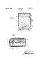
- Figure l is a central longitudinal sectional view through the entire machine, the lid or cover being open, and the record carrying panel and khorn dividingmeans beinginy its lowered position; c v
- Fig. 2 is a plan view of the cabinet or body of the machine, the cover or lid being removed andthe foldable portions ⁇ of the side wings being in folded position; n
- Fig. 3 is a view looking from the right in lig. 2, the cover being in place and closed, a side wall ofthe body and cover being removed, ⁇ and the record supporting panel being shown in section; Y
- FIG. 6 is shown the cabinet or body of the machine to one edge of which, preferably the rear edge, there is hingedly secured a lid or ⁇ cover 7
- a partitionvor'motor board 8 secured inv any suitable manner as for example by having its edges set into the ,Walls ofa cabinet orbody asshownat9.vk f
- the motor-boardor partition 8 is disposed relatively nearto the upper edge of the body 6 and a compartment 10V is formed beneath the motor board or between the motor board and the bottom 1l of the cabinet or body. At its rear edge the partition 8 is cut away as at 12 to form an exit for an amplifier 13 disposed within the compartment 10. The amplilier 13 willlater be more fully described..V
- the partition 8 supportsy any suitable motor. indicated at 14 which through avertical spindle 15 extending upwardlyl through the partition, drives a turntable 16.
- the turntable is for the 14 may be employed and that any type of turntable 16 may be employed, the particular type of motor or turntable having no relation to the present invention.
- the partition Through the forward end portion of the partition 8, or through that end or edge portion opposite the end or edge portion which is cut away as 12, the partition is provided with a sound entrance opening 18.
- the entrance opening 18 is located in one corner portion of the partition 8. Secured to the underside of the partition in a position to receive sound through the opening 18 is the entrance portion of the horn or amplifier 13 which entrance portion may take the form of a casting 21 curving laterally of the cabinet as it curves downwardly and secured as by a flange 22 to the rear or small end of a horn or megaphone 23 which is preferably of metal, as for example tin.
- This horn 23 as shown is substantially Vrectangular in cross section and comprises top, bottom and side walls and the casting may be secured to the horn as by bolts 24.
- the amplifier 13 is substantially the same as that disclosed in my patent above referred to and extends across the cabinet and then rearwardly therein, increasing in cross sectional 'area as it progresses from front to rear, and at its rear or discharge end being substantially the width of the cabinet.
- the side walls 25 and 26 of the horn portion 23 abut against the rear wall of the cabinet as does its bottom wall 27. These three walls are held in position and against rattle by meansof a block 28 having a curved surface 29 for the purposeof directing the sound upwardly through the cutout portion 12 of the partition.
- Top vwall 30 of the horn extends to a point substantially flush with the edge ⁇ of the cutout portion 12 and the rear edge portion of said wall 30 is rigidly secured to the partition as by means of a strap 31.
- Lid 7 is connected to the cabinet 6 as by means of a hinge 32 and the lid has secured to it a pair of side members or wings 33 preferably of metal. These members or wings 33 are adapted to move into slots 34 in the cabinet when the lid is moved to closed position and when the lid is in open position these members 33 close the corners at the connection between the cover or lid and the cabinet or body. In this manner an extension of the amplifier 13 is provided since the lid, side wings and partition 8 cooperate to provide a bell or mouth portion for the amplifier.
- a record carrier or panel 35 Mounted within the lid and movable about the same axis as that about which the'lid moves, is a record carrier or panel 35.
- This panel 35 is hingedly mounted through the medium of a bracket 36 bolted or otherwise secured to certain of the leaves of the hinge 32 as at 37. curved on its rear side as at 39 and co-operating with the upper edge or lip portion 40 of a metallic strip 41. This is probably best shown in Fig. 5 and the strips 38 and 41 cooperate to provide an unbroken surface at the hinged connection between the lid and record carrying member and the body.
- the panel 35 is movable to a position within the cover 7 where it may be temporarily held by means of a catch 42 co-operating with a catch plate 43.
- Links 44 pivoted within the lid as at 45 and slotted as at 46 to receive pins 47 on the edges of the panel operate to limit the swinging movement of the panel outwardly of the lid.
- a cover 48 is hinged to the panelV as at 49 whereby record compartment 50 is provided, records 51 being shown in the compartment in Fig. 5.
- The'V record compartment 50 begins at a point spaced from the rear or lower edge of the panel 35 and between its lower edge and the inner end oi the record compartment, the panel 35 has an opening 52 through it, the opening being preferably lined with metal as at 52a.
- This opening provides a passage whereby sound passing upwardly through the cut-out 12 in the partition 8 is divided, a portion of the sound passing up forwardly of the panel 35 and the remainder of the sound passing through the opening 52 and up between the cover 48 of the record compartment and the inner side of the cover 7.
- ⁇ Members or wings 54 and 55 may be temporarily secured in their extended positions by means of suitable catch members 57
- this catch means or members 57 need only be used vfor holding the wings 54 and 55 in their extended positions when the record carrying panel 35 is within the lid and secured by the catch 42. At other times, that is when the panel 35 is in open position it is disposed between the foldable side wings 54 and as shown in Figs. 1 and 4 and will hold them in theirextended positions.
- v Catches 59 may be used for securing the lid o r cover in closed position and may be provided with a carrying handle 60. Further, the exterior of the cabinet and the lid is preferably coveredy as with leather or imitation leatheras shown at 61.
- the wings or members 54 and 55 are preferably of metal, as for example brass, and to. prevent these parts from unnecessarily vibrating and also to have them so color ofthe covering material 6l, .these wings are ,preferablyI covered on their, inner and.
- a body a cover hinged to the ⁇ body at one edge thereof, an implifier within said body and positioned to discharge soundupwardly toward said cover, wingsr at theY sides of the discharge end of the amplifier and .extending between the cover and body whereby saidcover,'fside wings and body ⁇ cooperate tol forma Vcontinuation of thek amplier, a dividing means disposed inesaid conand meansfhingedly mounting the dividing'means for movemen into and out ofthe cover. j v y 2.
- a panel mounted to ocoupy'a position spacedy from the cover'and body when the cover is 1n open position, and said panel having an opening for the passage of soun whereby sound discharged by the amplifier passes upwardly at 4.
- a phonograph abody, to the body at one edgeV thereof and in its open position disposed at an angle above the body, an amplifier within said body and positioned to discharge sound upwardly toward ⁇ each side of the pane.
- a movable means adapted to occupy a position between the side wings when they are in their extended positions whereby to hold them in such positions, and said movable means dividing the continuation of the amplifier and having an opening therethrough whereby sound discharged from the amplifier passes through the continuation at each side of the means.
- a body member a cover member hinged to one edge of the body member, an amplifier wit-hin the body memberand disposed vto discharge sound in the direction of said cover member, stiff metal side wings hinged one to each of a pair of opposite portions of one of said members and adapted when in their extended positions to co-operate with the members whereby to form a continuation of the amplifier, and means carried by the other of said members to temporarily secure said side wings in their extended positions.
- a body member a cover member hinged to one edge of the body member, an amplifier within the body member and disposed to discharge sound in the direction of the cover member, side wings hinged to one of said' members and adapted when in their extended positions to co-opcrate with the members whereby to form a continuation of the amplifier, and a hingedly mounted means adapted to occupy a position between said side wings when the side wings are in extended positions whereby to divide kthe continuation of the amplifier, said hingedly mounted means adapted to be folded into one of said members when the cover member is to be moved to closed position.
- a body member a cover member hinged to one edge of the body member, an amplifier within the body memberk and arranged to discharge sound in the direction of the cover member, side wings hinged to one of said members and adapted when in their extended positions to cooperate with the members to provide a continuation of the amplifier, a dividing means hingedly connected with the other of said members, and said dividing means adapted to be moved to a position between the side wings when the side wings are in their extended positions.
- a body member a cover member hinged to one edge of the body member, an amplifier within the body member and arranged to discharge sound in the direction of the cover member, side wings hinged to one of said members and adapted when in their extended positions to co-operate with the members to provide a con-V tinuation of the amplifier, a dividing means hingedly connected with the other of said members, said dividing means adapted to be moved toa position betweenthe side wings when the side wings are in Vtheir extended positions, and ⁇ said side wings and dividing means adapted to be moved into the respective members to which they are hinged when the cover mem r is to be moved to closed position. 12.
- a body In a phonograph, a body, a cover hinged to the body at one edge thereof, an amplifier positioned to discharge sound upwardly toward said cover, wings at the sides of the discharge end of the amplifier and extending between the cover and body whereby said cover, side wings and body co-operate to form arcontinuation of the amplifier, a dividing means disposed in said continuation of the amplifier, and said dividing means having a sound passage therethrough whereby sound discharged from the amplifier passes outwardly of the phonograph between the body and the dividing means and between the dividing means and the cover.
- a body member In a phonograph, a body member, a cover member hinged to the body member along one edge thereof, a sound amplifier in said body member and positioned to direct sound upwardly toward the cover member, p
- a body member Ina phonograph, a body member, a cover member hinged to one edge of the body member, a sound amplifier in said body member and positioned to direct sound upwardly toward the cover member, side wings carried by the cover member at its hinged edge, said side wings being positioned one at each side of the discharge end of the amplifier when the cover member is open, other side win carried by the body member forwardly of the side' wings carried by the cover member, said second mentioned side wings hingedly mounted and when in their extended positions overlapping the forward edges ofthe first mentioned side wings and extending from the body member to the covermember, said side wings, body member and cover member cooperating to form a continuation of the amplifier, andv said second mentioned side VWings foldable into the body member to permit closing of the cover member.
- a phonograph comprisinga body, a cover hinged to one edge of said body, a panel foldable into the cover when the cover is closed and movable to a position betweenfthe cover and bodyy when the cover is open, an amplifier within said body and having its discharge opening positioned to direct sound in the direction of said panel, and means whereby the sound directed toward the panel is divided whereby it passes outwardly of the phonograph a part at each side of the panel. 16.
- AV phonograph comprising a body, a cover hinged to one edge of said body, a panel k1i oldable into the cover when the cover is closed and movable to a position between the cover and body when thecover is open, an amplifier within said body and having its discharge opening positioned to direct sound in the direction of said panel, said discharge opening being substantially the width of said panel, said panel having a passage therethrough, and said passage being ysubstantially the width of the panel whereby sound di- 415 rected 'toward the panel may pass outwardly of the phonograph at each side of the panel.
- a body member In a phonograph, a body member, a cover member hinged to the body member along yone edge thereof, a sound amplier in said body member and positioned to direct.
- a body member In a phonograph, a body member, a cover member hinged to the body member along one edge thereof, a sound amplier in said body member and positioned to direct sound upwardly toward the cover member,
Landscapes
- Casings For Electric Apparatus (AREA)
Description
April 12, 1932,. F. c. HINCKLEY PHONOGRAPH Filed Sept. 26, 1930 2 Sheets-Sheet l April 12A, 1932. F. c. HINCKLEY PHONOGRAPH 2 Sheets-Sheet 2 Filed Sepi.. 25, 1950 qui, y
Patented Apr. 12, 1932 UNITED stares PATENT* OFFICE FRANK C. HINCKLEY, F STRATFORD, CONNECTICUT, ASSIGNOR TO COLUMBIA PHONO- i GRAPH COMPANY, TNC., OF BRIDGEPORT, CONNECTICUT, A CORPORATION OF NEW` YORK PHONOGRAPH Application led September 26, 1930. Serial No. @4,4824
y V This invention relates to new and useful improvements in phonographs or talking machines and has particular relation to socalled portable phonographs, being an improvement on the structure shown in my United States Patentf1,776,905 of September 30th, 1930. i
An object of the invention is to p-rovide a phonograph which while small and compact and therefore particularly adapted for use as a portable or Stowaway phonograph yet is so constructed as to give large volume, its volume and tonal quality corresponding favorably with the volume and tonal quality of floor type phonographs. l
Another object is to provide a phonograph including animproved sound amplifying arrangement, the invention particularly relating to the bell or lmouthY portion of the amplifying system of anacoustic phonograph.
A further object is to provide a portable phonograph including a cover with which side wings co-operate when the cover is openwhereby to provide an extension for the horn or amplifier of the phonograph, a portionof said side wings being foldablewhereby when the machine isV closed as for transportation a compact and relatively small structure is had.
An additional Objectis to'provide a phono-y graph having characteristics statedr and wherein a record carrier ory other means within the lid or coveris so constructed that it divides the "bell or mouth portion of the amplifier which bell or mouth portion is formed by the cover ,and side wings inassociation with the body of the machine. kOther-objects and advantages will becom apparent from a consideration ofthe vfollowing description taken in connection withy the accompanying drawings whereinasatisfactory embodiment of the invention is shown. However, it isv to be understood that the invention is'not limited to the details disclosed since changes in the construction, combination and arrangement of parts will readily suggest themselves to' thosek skilled in the art. Since the invention comprehends all such variations and modifications as fall d within the scope of the appended claims, reference must be made to the annexed claims Figure l is a central longitudinal sectional view through the entire machine, the lid or cover being open, and the record carrying panel and khorn dividingmeans beinginy its lowered position; c v
Fig. 2 is a plan view of the cabinet or body of the machine, the cover or lid being removed andthe foldable portions` of the side wings being in folded position; n
Fig. 3 is a view looking from the right in lig. 2, the cover being in place and closed, a side wall ofthe body and cover being removed,` and the record supporting panel being shown in section; Y
Fig. 4 is a perspective view ofthe bell Vor mrith portion arrangement of the amplier; an A Fig. 5 is an enlarged sectional detail view showing the mounting for the lid orcover and the record carrying panel or horn dividing means. l
Referring in `detail tothe drawings,at 6 is shown the cabinet or body of the machine to one edge of which, preferably the rear edge, there is hingedly secured a lid or` cover 7 Within the cabinet or body 6 thereis dis# posed 'a partitionvor'motor board 8 secured inv any suitable manner as for example by having its edges set into the ,Walls ofa cabinet orbody asshownat9.vk f
The motor-boardor partition 8 is disposed relatively nearto the upper edge of the body 6 and a compartment 10V is formed beneath the motor board or between the motor board and the bottom 1l of the cabinet or body. At its rear edge the partition 8 is cut away as at 12 to form an exit for an amplifier 13 disposed within the compartment 10. The amplilier 13 willlater be more fully described..V
At itsunder side the partition 8 supportsy any suitable motor. indicated at 14 which through avertical spindle 15 extending upwardlyl through the partition, drives a turntable 16. Obviously, the turntable is for the 14 may be employed and that any type of turntable 16 may be employed, the particular type of motor or turntable having no relation to the present invention.
Through the forward end portion of the partition 8, or through that end or edge portion opposite the end or edge portion which is cut away as 12, the partition is provided with a sound entrance opening 18. A tone arm 19 carrying a reproducer 20 for cooperation with a record on the turntable 16, is secured to the partition 8 in a position to align its discharge end with the entrance opening 18 through thepartition 8.
It is to be noted that the entrance opening 18 is located in one corner portion of the partition 8. Secured to the underside of the partition in a position to receive sound through the opening 18 is the entrance portion of the horn or amplifier 13 which entrance portion may take the form of a casting 21 curving laterally of the cabinet as it curves downwardly and secured as by a flange 22 to the rear or small end of a horn or megaphone 23 which is preferably of metal, as for example tin.
This horn 23 as shown is substantially Vrectangular in cross section and comprises top, bottom and side walls and the casting may be secured to the horn as by bolts 24. As herein disclosed the amplifier 13 is substantially the same as that disclosed in my patent above referred to and extends across the cabinet and then rearwardly therein, increasing in cross sectional 'area as it progresses from front to rear, and at its rear or discharge end being substantially the width of the cabinet. The side walls 25 and 26 of the horn portion 23 abut against the rear wall of the cabinet as does its bottom wall 27. These three walls are held in position and against rattle by meansof a block 28 having a curved surface 29 for the purposeof directing the sound upwardly through the cutout portion 12 of the partition. Top vwall 30 of the horn extends to a point substantially flush with the edge `of the cutout portion 12 and the rear edge portion of said wall 30 is rigidly secured to the partition as by means of a strap 31.
Mounted within the lid and movable about the same axis as that about which the'lid moves, is a record carrier or panel 35. This panel 35 is hingedly mounted through the medium of a bracket 36 bolted or otherwise secured to certain of the leaves of the hinge 32 as at 37. curved on its rear side as at 39 and co-operating with the upper edge or lip portion 40 of a metallic strip 41. This is probably best shown in Fig. 5 and the strips 38 and 41 cooperate to provide an unbroken surface at the hinged connection between the lid and record carrying member and the body.
The panel 35 is movable to a position within the cover 7 where it may be temporarily held by means of a catch 42 co-operating with a catch plate 43. Links 44 pivoted within the lid as at 45 and slotted as at 46 to receive pins 47 on the edges of the panel operate to limit the swinging movement of the panel outwardly of the lid. A cover 48 is hinged to the panelV as at 49 whereby record compartment 50 is provided, records 51 being shown in the compartment in Fig. 5.
The'V record compartment 50 begins at a point spaced from the rear or lower edge of the panel 35 and between its lower edge and the inner end oi the record compartment, the panel 35 has an opening 52 through it, the opening being preferably lined with metal as at 52a. This opening provides a passage whereby sound passing upwardly through the cut-out 12 in the partition 8 is divided, a portion of the sound passing up forwardly of the panel 35 and the remainder of the sound passing through the opening 52 and up between the cover 48 of the record compartment and the inner side of the cover 7.
Hinged as at 53 to the side walls of the cabinet 6, are ak pair of foldable wings or members 54 and 55. These members, when open or in extended positions, are so disposed with relation to the side wings 33 as to overlap the forward edges of rsuch wings 1 and further the members 54 and 55 extend upwardly and at their upper or free edges bear against the inner surface of the side rails or edges of the lid 7 as shown at 56.V
`Members or wings 54 and 55 may be temporarily secured in their extended positions by means of suitable catch members 57 However, this catch means or members 57 need only be used vfor holding the wings 54 and 55 in their extended positions when the record carrying panel 35 is within the lid and secured by the catch 42. At other times, that is when the panel 35 is in open position it is disposed between the foldable side wings 54 and as shown in Figs. 1 and 4 and will hold them in theirextended positions.
It is, of course, only when the panel 35 is in its open or extended position as shown in Figs. 1 and 4 that a divided bell or mouth portion is provided for the amplifier. lVith Panel 35 carries a. strip 38 Q tinuation,
.the panel in its closed position, that is, with the panel within the lid and secured by the catch 42 but one large bellor mouth is provided for the amplifier, that bell or mouth `being forwardly of the panel: 35. However, this bell or mouth portion will be considerably `larger than that heretofore provided. Also,.when the panel is in open position the double or divided bell or mouth portion Lis obtained. f
. Whenthe machine Vis to be folded as for transportation, it is but necessary to release the members or wings 54 or 55 from the catches 57 ,to move the panel to a position within the lid and tothen fold the wings 54 and 55:.one upon the other as shown inFig. 2. Thelid or cover 7 vmay then be lowered to the positionshown iny Fig. 3,-the-lid having -been secured in open position by means of a catch member 58 cto-operating with one of they wings 33. V
v Catches 59 may be used for securing the lid o r cover in closed position and may be provided with a carrying handle 60. Further, the exterior of the cabinet and the lid is preferably coveredy as with leather or imitation leatheras shown at 61. The wings or members 54 and 55 are preferably of metal, as for example brass, and to. prevent these parts from unnecessarily vibrating and also to have them so color ofthe covering material 6l, .these wings are ,preferablyI covered on their, inner and.
outer` surfaces with such material designated 62 which may be glued or cemented or otherwise secured to them. s
Having thus described the invention, what is claimed is: f Y
1. In a phonograph,.a body, a cover hinged to the `body at one edge thereof, an implifier within said body and positioned to discharge soundupwardly toward said cover, wingsr at theY sides of the discharge end of the amplifier and .extending between the cover and body whereby saidcover,'fside wings and body `cooperate tol forma Vcontinuation of thek amplier, a dividing means disposed inesaid conand meansfhingedly mounting the dividing'means for movemen into and out ofthe cover. j v y 2. In a phonograph,fa body, a cover hinged tothe body atone edge thereof, an amplifier within said body and positioned to discharge sound upwardly toward said cover, wings at the sides of thedischarge end of the amplifier and closing the space .between the cover iand s body Awhereby said cover, si le wings and bodyl co-operate toi form a continuation of the amplilier, a panel hinged within thercover, and said panelhaving an opening therethrough for the passageof sound whereby sound discharged from the amplifier of the phonograph between panel and ,between 3.A In a phonograph, a body,.a cover hinged the body and the the cabinet far as possible match the,v
passes outwardly the panel yand the cover.
said cover, a panel mounted to ocoupy'a position spacedy from the cover'and body when the cover is 1n open position, and said panel having an opening for the passage of soun whereby sound discharged by the amplifier passes upwardly at 4. In a phonograph, abody, to the body at one edgeV thereof and in its open position disposed at an angle above the body, an amplifier within said body and positioned to discharge sound upwardly toward `each side of the pane.
ying a position spaced from the cover Vand body when the cover is in open-position, said panel adaptedto be moved to a position within .the cover when the cover is in closedposition, and said panel having an opening for the passage of sound whereby sound ldischarged bythe amplier passes upwardly'at each side of the panel when the panel is spaced from thecover and body. 5. In a phonograph, a body cover member hinged to one edge member, Lan amplifier withinthe body member and arranged to discharge sound upwardlytowardy said cover member, sidev wings hinged to one of said members and adapted when `the cover member is in open position to be moved to positions extending between the body member and the cover member one member, a
at each side fof the discharge endof the-ammember hinged to one edge ofthe body mem- .i
ber, an amplifierwithin the body member and disposed to discharge sound towards said cover member, side wings hinged to one of said. members andadapted when ink their eX- tended positions to co-operate with the members whereby to form a continuation of-the amplifier, a movable means adapted tov occupy a position between said side wings when of the body l 'V15 a cover hinged ,S said cover, a hingedly mounted panel occuthe side wings are iny extended positions i whereby to divide the continuation of the amplifier, and said dividing means movable into the cover when the cover is moved to closed position. s
7 .In a phonograph, a-body member, Aa cover member hingedto one yedge of the-body member, an amplifier within the Abody mem.- ber and disposed to 'discharge sound towards said cover member, sidel wings hinged to one of said members and adapted when` in their extended positions to co-'operate withr the members whereby to forma continuation; of
the amplifier, a movable means adapted to occupy a position between the side wings when they are in their extended positions whereby to hold them in such positions, and said movable means dividing the continuation of the amplifier and having an opening therethrough whereby sound discharged from the amplifier passes through the continuation at each side of the means.
8. In a phonograph, a body member, a cover member hinged to one edge of the body member, an amplifier wit-hin the body memberand disposed vto discharge sound in the direction of said cover member, stiff metal side wings hinged one to each of a pair of opposite portions of one of said members and adapted when in their extended positions to co-operate with the members whereby to form a continuation of the amplifier, and means carried by the other of said members to temporarily secure said side wings in their extended positions.
9. In a phonograph, a body member, a cover member hinged to one edge of the body member, an amplifier within the body member and disposed to discharge sound in the direction of the cover member, side wings hinged to one of said' members and adapted when in their extended positions to co-opcrate with the members whereby to form a continuation of the amplifier, and a hingedly mounted means adapted to occupy a position between said side wings when the side wings are in extended positions whereby to divide kthe continuation of the amplifier, said hingedly mounted means adapted to be folded into one of said members when the cover member is to be moved to closed position.
10. In a phonograph, a body member, a cover member hinged to one edge of the body member, an amplifier within the body memberk and arranged to discharge sound in the direction of the cover member, side wings hinged to one of said members and adapted when in their extended positions to cooperate with the members to provide a continuation of the amplifier, a dividing means hingedly connected with the other of said members, and said dividing means adapted to be moved to a position between the side wings when the side wings are in their extended positions.
11. In a phonograph, a body member, a cover member hinged to one edge of the body member, an amplifier within the body member and arranged to discharge sound in the direction of the cover member, side wings hinged to one of said members and adapted when in their extended positions to co-operate with the members to provide a con-V tinuation of the amplifier, a dividing means hingedly connected with the other of said members, said dividing means adapted to be moved toa position betweenthe side wings when the side wings are in Vtheir extended positions, and `said side wings and dividing means adapted to be moved into the respective members to which they are hinged when the cover mem r is to be moved to closed position. 12. In a phonograph, a body, a cover hinged to the body at one edge thereof, an amplifier positioned to discharge sound upwardly toward said cover, wings at the sides of the discharge end of the amplifier and extending between the cover and body whereby said cover, side wings and body co-operate to form arcontinuation of the amplifier, a dividing means disposed in said continuation of the amplifier, and said dividing means having a sound passage therethrough whereby sound discharged from the amplifier passes outwardly of the phonograph between the body and the dividing means and between the dividing means and the cover. i
13. In a phonograph, a body member, a cover member hinged to the body member along one edge thereof, a sound amplifier in said body member and positioned to direct sound upwardly toward the cover member, p
side wings at each side of the discharge end of the amplifier, other side wings carried by onel of said members forwardly of the first mentioned side wings, said second mentioned side wings hingedly mounted and when in their extended posit-ions overlapping the forward edges of the first mentioned side wings and extending from one of said members to the other thereof, and said side wings, body member and cover member co-operating to form a continuation of the amplifier.
14. Ina phonograph, a body member, a cover member hinged to one edge of the body member, a sound amplifier in said body member and positioned to direct sound upwardly toward the cover member, side wings carried by the cover member at its hinged edge, said side wings being positioned one at each side of the discharge end of the amplifier when the cover member is open, other side win carried by the body member forwardly of the side' wings carried by the cover member, said second mentioned side wings hingedly mounted and when in their extended positions overlapping the forward edges ofthe first mentioned side wings and extending from the body member to the covermember, said side wings, body member and cover member cooperating to form a continuation of the amplifier, andv said second mentioned side VWings foldable into the body member to permit closing of the cover member. v
15. A phonograph comprisinga body, a cover hinged to one edge of said body, a panel foldable into the cover when the cover is closed and movable to a position betweenfthe cover and bodyy when the cover is open, an amplifier within said body and having its discharge opening positioned to direct sound in the direction of said panel, and means whereby the sound directed toward the panel is divided whereby it passes outwardly of the phonograph a part at each side of the panel. 16. AV phonograph comprising a body, a cover hinged to one edge of said body, a panel k1i oldable into the cover when the cover is closed and movable to a position between the cover and body when thecover is open, an amplifier within said body and having its discharge opening positioned to direct sound in the direction of said panel, said discharge opening being substantially the width of said panel, said panel having a passage therethrough, and said passage being ysubstantially the width of the panel whereby sound di- 415 rected 'toward the panel may pass outwardly of the phonograph at each side of the panel.
17. In a phonograph, a body member, a cover member hinged to the body member along yone edge thereof, a sound amplier in said body member and positioned to direct.
sound upwardly toward the cover member, side wings at each side of the discharge end of the amplier, other side wings carried by one of said members forwardly of the i'irst mentioned side wings, said second mentioned side wings hingedly mounted yand when in their extended positions extending from one of said members to the other thereof, said side wings, body member and cover member co-operating to form a continuation ofthe amplifier, and a panel hingedly mounted by one of said members and movable to and from a position to divide said continuation of the ampliiier.
18. In a phonograph, a body member, a cover member hinged to the body member along one edge thereof, a sound amplier in said body member and positioned to direct sound upwardly toward the cover member,
side wings at each side of the discharge end of the amplifier, other side wings carried by one of said members forwardly of the first mentioned side wings, said second mentioned side wings hingedly mounted and when in their extended positions extendingfrom one of saidmembers to the other thereof, said side Wings, body member and cover member co-operating to form a continuation of the amplier, a panel hingedly mounted by one of said 5c members and movable to and from a position to divide said continuation of the amplier, and said panel having an opening therethrough whereby soundy passes through said continuation of the ampliiier at each side 0f the panel. Y
Signed at Bridgeport, in the county of Fairfield, and State of Connecticut, this 23 day of September, 1930.
FRANK C. HINCKLEY.
Priority Applications (1)
| Application Number | Priority Date | Filing Date | Title |
|---|---|---|---|
| US484482A US1853210A (en) | 1930-09-26 | 1930-09-26 | Phonograph |
Applications Claiming Priority (1)
| Application Number | Priority Date | Filing Date | Title |
|---|---|---|---|
| US484482A US1853210A (en) | 1930-09-26 | 1930-09-26 | Phonograph |
Publications (1)
| Publication Number | Publication Date |
|---|---|
| US1853210A true US1853210A (en) | 1932-04-12 |
Family
ID=23924329
Family Applications (1)
| Application Number | Title | Priority Date | Filing Date |
|---|---|---|---|
| US484482A Expired - Lifetime US1853210A (en) | 1930-09-26 | 1930-09-26 | Phonograph |
Country Status (1)
| Country | Link |
|---|---|
| US (1) | US1853210A (en) |
-
1930
- 1930-09-26 US US484482A patent/US1853210A/en not_active Expired - Lifetime
Similar Documents
| Publication | Publication Date | Title |
|---|---|---|
| US2722352A (en) | Attachable tool box for utilities trucks | |
| US2335898A (en) | Toilet case | |
| US2535455A (en) | Compact | |
| US1853210A (en) | Phonograph | |
| US2467545A (en) | Display box with pivoted closure | |
| US2334079A (en) | Combination luggage | |
| US2005198A (en) | Automobile door | |
| US1776905A (en) | Cabinet phonograph | |
| US1407309A (en) | Phonograph cabinet | |
| US1923558A (en) | Talking machine | |
| US1185988A (en) | Talking-machine. | |
| US1461859A (en) | Portable casing for talking machines | |
| US1837642A (en) | Talking machine | |
| US1653967A (en) | Mechanical box | |
| US1424835A (en) | Phonograph construction and housing | |
| US1540349A (en) | Vanity case | |
| US946442A (en) | Talking-machine. | |
| USRE16993E (en) | stechbart | |
| US1444788A (en) | Cabinet phonograph | |
| US1687566A (en) | Sound-control construction | |
| US1554621A (en) | Portable phonograph | |
| US1654804A (en) | Combined radio and talking-machine amplifier | |
| US946243A (en) | Cabinet for sound-reproducing machines. | |
| US1362919A (en) | Variable sound-conveyer or horn for talking-machines or the like | |
| GB320204A (en) | Improvements in talking machines |