US1853101A - Electric welding machine - Google Patents
Electric welding machine Download PDFInfo
- Publication number
- US1853101A US1853101A US134759A US13475926A US1853101A US 1853101 A US1853101 A US 1853101A US 134759 A US134759 A US 134759A US 13475926 A US13475926 A US 13475926A US 1853101 A US1853101 A US 1853101A
- Authority
- US
- United States
- Prior art keywords
- conductor
- flexible
- conductors
- welding machine
- electric welding
- Prior art date
- Legal status (The legal status is an assumption and is not a legal conclusion. Google has not performed a legal analysis and makes no representation as to the accuracy of the status listed.)
- Expired - Lifetime
Links
- 238000003466 welding Methods 0.000 title description 9
- 239000004020 conductor Substances 0.000 description 42
- 210000002445 nipple Anatomy 0.000 description 8
- XLYOFNOQVPJJNP-UHFFFAOYSA-N water Substances O XLYOFNOQVPJJNP-UHFFFAOYSA-N 0.000 description 6
- 239000012809 cooling fluid Substances 0.000 description 5
- 238000010276 construction Methods 0.000 description 3
- 239000000463 material Substances 0.000 description 3
- RYGMFSIKBFXOCR-UHFFFAOYSA-N Copper Chemical compound [Cu] RYGMFSIKBFXOCR-UHFFFAOYSA-N 0.000 description 2
- 229910052802 copper Inorganic materials 0.000 description 2
- 239000010949 copper Substances 0.000 description 2
- 239000011810 insulating material Substances 0.000 description 2
- 238000005476 soldering Methods 0.000 description 2
- 102100035683 Axin-2 Human genes 0.000 description 1
- 101700047552 Axin-2 Proteins 0.000 description 1
- 238000001816 cooling Methods 0.000 description 1
- 239000000110 cooling liquid Substances 0.000 description 1
- 238000010586 diagram Methods 0.000 description 1
- 239000012530 fluid Substances 0.000 description 1
- 230000004927 fusion Effects 0.000 description 1
- VKYKSIONXSXAKP-UHFFFAOYSA-N hexamethylenetetramine Chemical compound C1N(C2)CN3CN1CN2C3 VKYKSIONXSXAKP-UHFFFAOYSA-N 0.000 description 1
- 230000001939 inductive effect Effects 0.000 description 1
- 239000007788 liquid Substances 0.000 description 1
- 238000012856 packing Methods 0.000 description 1
- 230000035900 sweating Effects 0.000 description 1
- 239000004636 vulcanized rubber Substances 0.000 description 1
Images
Classifications
-
- H—ELECTRICITY
- H01—ELECTRIC ELEMENTS
- H01B—CABLES; CONDUCTORS; INSULATORS; SELECTION OF MATERIALS FOR THEIR CONDUCTIVE, INSULATING OR DIELECTRIC PROPERTIES
- H01B9/00—Power cables
- H01B9/001—Power supply cables for the electrodes of electric-welding apparatus or electric-arc furnaces
-
- B—PERFORMING OPERATIONS; TRANSPORTING
- B23—MACHINE TOOLS; METAL-WORKING NOT OTHERWISE PROVIDED FOR
- B23K—SOLDERING OR UNSOLDERING; WELDING; CLADDING OR PLATING BY SOLDERING OR WELDING; CUTTING BY APPLYING HEAT LOCALLY, e.g. FLAME CUTTING; WORKING BY LASER BEAM
- B23K11/00—Resistance welding; Severing by resistance heating
- B23K11/30—Features relating to electrodes
- B23K11/3009—Pressure electrodes
- B23K11/3018—Cooled pressure electrodes
Definitions
- Fig. 2 is a view partly in section of the head
- Fig. 3 is a fragmentary view showing certain parts in section; 25 Fig. 4 is a view of the water connections;
- Fig. 5 is a view of the-same parts shown in Fi 4 atan angle of 90 therefrom;
- Fig. 6 is a section of a portion of the flexible conductors and water connections therefor; 30 and Fig. 7 is a diagram of the electrical cir cuits.
- the welder consists of a transformer A, a head B and a flexible con- 35 ductor C.
- the transformer consists of a primary 1, an auto coil 2, with taps 18 and an adjustable conductor 3 for connection with an one of the taps.
- the trans former, insofhr as the primary and core are 0 concerned, is of the usual construction.
- the secondar 4 consists of the desired number of turns of ollow pipe of conducting material. In this articular instance, the secondary is provided with three turns.
- This hollow pipe 5 extends down through and around the core 5 of the transformer, as shown in Fig. 1. Connected with the ends of the secondary conductor are connectors ,6 and 7 of conducting material. As shown in Fig.
- one end of the 50 connector 6 is'split at 8-and a bolt 9 passed through the same to clamp the end of the secon ary 4 in the connector.
- the connector is also provided with a nipple 10 through which water flows into a channel 11 which communicates with the interior of the flexible conductor 12.
- the flexible conductor 13 also passes through the connection 6 and enters an opening in the connector]? which in turn communicates with a nipple 15.
- One endof the connector 7 is split at 16 and a bolt 17 is threaded into this connector and acts to clamp the end of the secondary 4 in place.
- the flexible conductor which conveys the energy from the transformer secondary to the welding electrodes.
- This conductor will now be described. It consists of two conductors 12 and 13, with the conductor 13 inside the conductor 12 and preferably concentric therewith.
- the conductors 12 and 13 are preferably made of corrugated copper tubing and are flexible in all directions. These two conductors are kept in spaced relation to each other by braided wire 18 which is placed around the conductor 13, between it and the flexible insulating material 19.
- the material 19 is preferably a flexible tube of any known construction, usually consisting of canvas and partially vulcanized rubber.
- the end of the conductor 13 is fastened in the connector 7 by any suitable means such as soldering. @1- it may be sweated in position... I
- a rubber ring 20 is placed around the tube 19, and a packing nut 21 when screwed down on said ring forms a water tight connection.
- Conductor 12 is surrounded by braided wire 22, and around this is placed a flexible tube 23 of the same construction as that of the tube 19. The end of the conductor 12 is fastened in the connector 6 by soldering or sweating.
- Fig. 2 shows the other end of the flexible conductor C and its connection with the welding head.
- the conductor is soldered or sweated into the connector 24 which is bolted to the head 25 by bolts 26.
- the head comprises a frame 27 by which are carried two electrode holders 28 and 29. Electrodes 30 and 31 are held in the electrode 100 holders.
- the holders may be of any suitable material, preferably copper, and are prov1ded I with channels 32 and 33, respectively.
- cooling liquid such as water is circulated through thesechannels for cool n the electrodes as will be ex lained in detai later.
- the electrode ho der 29 is movable with respect to the holder 28 by the followmgmechamsm:
- An operating handle '34 is pivotal ⁇ ; mounted on the frame at 35.
- the bell era 36 is pivotally connected with a link 37.
- link 37 connects with links 38 and 39, all three of which are pivotally connected together at 40.
- the link 39 is pivoted to the frame at 41 and the link 38 is pivotal] attached to the electrode holder 29 at 42 t rough slide bars 42'.
- a spring 43 connects at one end with the bell crank 36 and at the other end to an adjustable hook 44 carried by the frame.
- a coil spring 45 surrounds the electrode holder 29 betweenslide bars 42' and tends to move the electrodes and 31 into contact with work between them.
- One end of the spring 45 is fixed tothe' slide bars 42' by a member 46 and the other end is connected with the electrode holder 29 by a member 47.
- the handle 34 When it is desired to separate the electrodes 4 30 and 31, the handle 34 is rotated in a counter clockwise direction. When it is desired to move the electrodes into engagement with the work 48, the handle 34 is rotated in a clockwise direction which straightens out the and thence to the tool shown in Fig. 2.
- the outer conductor the li uid' passes throu h the passage 58, through t e electrode hol er 29 and then backthrough the passage 59 to the flexible conductor 60, thence to the nipple 61 of the electrode holder 28, thence through the channel 32 back to the flexible conductor 62, thence to the inner conductor 13 to the nipple 15.
- the liquid is from each other an conducted through the flexible pipe 63 to the secondary conductor 4. It passes through the secondary-4 u to the nipple 64 and out 'through the pipe 5.
- the cooling fluid passes first through the conductor 0 to and through the electrode holders, back through the conductor G, and thence throu h. the secondar of the transformer, there y cooling all 0 these parts so as to keep their temperature down to the desired amount.
- a flexible conductor for high current density comprising two corrugated hollow conductors, one inside the other, flexible insulating means for se arating saidconductors means for supplying cooling fluid to said conductors.
- a flexible conductor for high current density comprising two corrugated hollow conductors, one inside the other, flexible insulating means for separating said conductors from each other and me ns for supplyinlg cooling fluid to said conductors separate 3.
- flexible electrical conductor consisting of two-hollow concentric flexible fluid-' ti ht conductors, connectors on the ends of said conductor, said connectors having chan- -ne1s communicating with the interiors of said concentric conductors andmeans for insulating said conductors from each other.
Landscapes
- Engineering & Computer Science (AREA)
- Mechanical Engineering (AREA)
- Manufacturing Of Electrical Connectors (AREA)
Description
April 12, 1932. VQN HENKE 1,853,101
ELECTRIC WELDING MACHINE Filed Sept. 11, 1926 3 Sheets-Sheet l z ATTORNEYS.
April 12, 1932. v E. J. VON HENKE ELECTRIC WELDING MACHINE Filed Sept. 11, 1926 3 Sheets-Sheet 2 l IVNTOR April 1932- E. J. VON HENKE 1,853,101
ELECTRIC WELDING MACHINE Filed Sept. 11, 1926 3 Sheets-Sheet 3 4.1TTORNEYJ Patented Apr. 12, 1932 UNITED STATES PATENT OFFICE EDMUND J. VON HENKE, OF CHICAGO, ILLINOIS, ASSIGNOR TO AMERICAN" ELECTRIC FUSION CORPORATION, O... CHICAGO, ILLINOIS, A CORPORATION OF ILLINOIS ELECTRIC WELDING MACHINE Application filed September 11, 1926. Seriai No. 134,759.
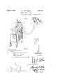
7 15 My invention will be better understood by reference to the following description taken in connection with the accompanying drawin s, in which ig. 1 is a perspective view ofthe complete l welder;
Fig. 2 is a view partly in section of the head; 1
Fig. 3 is a fragmentary view showing certain parts in section; 25 Fig. 4 is a view of the water connections;
Fig. 5 is a view of the-same parts shown in Fi 4 atan angle of 90 therefrom;
Fig. 6 is a section of a portion of the flexible conductors and water connections therefor; 30 and Fig. 7 is a diagram of the electrical cir cuits. I
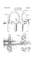
Broadly considered, the welder consists of a transformer A, a head B and a flexible con- 35 ductor C. In detail, the transformer consists of a primary 1, an auto coil 2, with taps 18 and an adjustable conductor 3 for connection with an one of the taps. The trans former, insofhr as the primary and core are 0 concerned, is of the usual construction. The secondar 4 consists of the desired number of turns of ollow pipe of conducting material. In this articular instance, the secondary is provided with three turns. This hollow pipe 5 extends down through and around the core 5 of the transformer, as shown in Fig. 1. Connected with the ends of the secondary conductor are connectors ,6 and 7 of conducting material. As shown in Fig. 6 one end of the 50 connector 6 is'split at 8-and a bolt 9 passed through the same to clamp the end of the secon ary 4 in the connector. The connector is also provided with a nipple 10 through which water flows into a channel 11 which communicates with the interior of the flexible conductor 12. The flexible conductor 13 also passes through the connection 6 and enters an opening in the connector]? which in turn communicates with a nipple 15. One endof the connector 7 is split at 16 and a bolt 17 is threaded into this connector and acts to clamp the end of the secondary 4 in place.
One of the important features of my invention is the flexible conductorwhich conveys the energy from the transformer secondary to the welding electrodes. This conductor will now be described. It consists of two conductors 12 and 13, with the conductor 13 inside the conductor 12 and preferably concentric therewith. The conductors 12 and 13 are preferably made of corrugated copper tubing and are flexible in all directions. These two conductors are kept in spaced relation to each other by braided wire 18 which is placed around the conductor 13, between it and the flexible insulating material 19. The material 19 is preferably a flexible tube of any known construction, usually consisting of canvas and partially vulcanized rubber. The end of the conductor 13 is fastened in the connector 7 by any suitable means such as soldering. @1- it may be sweated in position... I
A rubber ring 20 is placed around the tube 19, and a packing nut 21 when screwed down on said ring forms a water tight connection.
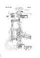
Fig. 2 shows the other end of the flexible conductor C and its connection with the welding head. The conductor is soldered or sweated into the connector 24 which is bolted to the head 25 by bolts 26.
The head comprises a frame 27 by which are carried two electrode holders 28 and 29. Electrodes 30 and 31 are held in the electrode 100 holders. The holders may be of any suitable material, preferably copper, and are prov1ded I with channels 32 and 33, respectively. A
cooling liquid such as water is circulated through thesechannels for cool n the electrodes as will be ex lained in detai later.
The electrode ho der 29 is movable with respect to the holder 28 by the followmgmechamsm: An operating handle '34 is pivotal}; mounted on the frame at 35. The bell era 36 is pivotally connected with a link 37. The
link 37 connects with links 38 and 39, all three of which are pivotally connected together at 40. The link 39 is pivoted to the frame at 41 and the link 38 is pivotal] attached to the electrode holder 29 at 42 t rough slide bars 42'. A spring 43 connects at one end with the bell crank 36 and at the other end to an adjustable hook 44 carried by the frame. A coil spring 45 surrounds the electrode holder 29 betweenslide bars 42' and tends to move the electrodes and 31 into contact with work between them. One end of the spring 45 is fixed tothe' slide bars 42' by a member 46 and the other end is connected with the electrode holder 29 by a member 47.
When it is desired to separate the electrodes 4 30 and 31, the handle 34 is rotated in a counter clockwise direction. When it is desired to move the electrodes into engagement with the work 48, the handle 34 is rotated in a clockwise direction which straightens out the and thence to the tool shown in Fig. 2.
tog 1e 3839. This moves the slide bars 42 to t e rightand puts the electrode 31 into engagement with the work. Any further movement of the toggleis taken up b the spring-45, which is compressed by re ative movement between slide bars 42' and holder Referring to Figs. 1 and 7, it will be noted I will now trace the flow of cooling fluid through the arts to be cooled. Water enters through t e nipple 54 (Fig. 1) and passes up through a pipe 55 provided with a valve 56. It then passes through a flexible hose 57 to the nipple 10, through the passage 11 to the interior of the conductor 12 (Fig. 6),
the outer conductor the li uid' passes throu h the passage 58, through t e electrode hol er 29 and then backthrough the passage 59 to the flexible conductor 60, thence to the nipple 61 of the electrode holder 28, thence through the channel 32 back to the flexible conductor 62, thence to the inner conductor 13 to the nipple 15. From the nipple 15 the liquid is from each other an conducted through the flexible pipe 63 to the secondary conductor 4. It passes through the secondary-4 u to the nipple 64 and out 'through the pipe 5.
From the fore oing it will be seen that the cooling fluid passes first through the conductor 0 to and through the electrode holders, back through the conductor G, and thence throu h. the secondar of the transformer, there y cooling all 0 these parts so as to keep their temperature down to the desired amount.
B reason of the arrangements above doscri d, I produce a portable welder which may be moved from place to place on the carriage, which, when connected with a power circuit, may be used for welding any desired parts of an automobile -or other article in-an efiicient and expeditious-manner; the flexible conductor connecting the transformer with the welding head avoids any unbalancing from an electrical standpoint because of the fact that the two conductors 12 and 13,
are one inside the other and held concentric with respect to each other, thereby avoiding. all magnetic and other inductive 'eflects which, with the large current used, would be a serious roblem. I
Notwit standing all of the advantages above mentioned which are secured by myinvention, I have succeeded in produclng a simple, economical and compact machine.
Further advantages will be appreciated by those skilled in the art.
I claim: Y I n a 1. A flexible conductor for high current density comprising two corrugated hollow conductors, one inside the other, flexible insulating means for se arating saidconductors means for supplying cooling fluid to said conductors.
2. A flexible conductor for high current density comprising two corrugated hollow conductors, one inside the other, flexible insulating means for separating said conductors from each other and me ns for supplyinlg cooling fluid to said conductors separate 3. flexible electrical conductor consisting of two-hollow concentric flexible fluid-' ti ht conductors, connectors on the ends of said conductor, said connectors having chan- -ne1s communicating with the interiors of said concentric conductors andmeans for insulating said conductors from each other. I
4. In combination, two flexible tubular members disposed one within the other and each formed of electrical conductin material, flexible insulating means dispose between said members, flexible insulating means covering the outer member, and connections to said members for supplying cooling fluid thereto.
5. In combination, two flexible tubular members disposed onewithin the other and each formed of electrical conducting material, and a flexible tube of insulating material disposed between said members and spaced from the outer one, said tube and said outer member formin between them a channel for theflow of coo ing fluid.
EDMUND J. VON HENKE.
Priority Applications (2)
| Application Number | Priority Date | Filing Date | Title |
|---|---|---|---|
| US134759A US1853101A (en) | 1926-09-11 | 1926-09-11 | Electric welding machine |
| US224292A US1723984A (en) | 1926-09-11 | 1927-10-06 | Electric welding machine |
Applications Claiming Priority (1)
| Application Number | Priority Date | Filing Date | Title |
|---|---|---|---|
| US134759A US1853101A (en) | 1926-09-11 | 1926-09-11 | Electric welding machine |
Publications (1)
| Publication Number | Publication Date |
|---|---|
| US1853101A true US1853101A (en) | 1932-04-12 |
Family
ID=22464857
Family Applications (1)
| Application Number | Title | Priority Date | Filing Date |
|---|---|---|---|
| US134759A Expired - Lifetime US1853101A (en) | 1926-09-11 | 1926-09-11 | Electric welding machine |
Country Status (1)
| Country | Link |
|---|---|
| US (1) | US1853101A (en) |
Cited By (14)
| Publication number | Priority date | Publication date | Assignee | Title |
|---|---|---|---|---|
| US2433495A (en) * | 1945-05-31 | 1947-12-30 | Allis Chalmers Mfg Co | Tilting induction furnace with leads extending through a trunnion |
| US2433588A (en) * | 1944-05-15 | 1947-12-30 | Frederick S Wreford | Welding cable |
| US2479705A (en) * | 1946-08-23 | 1949-08-23 | Joseph Waitcus | Power conversion system and apparatus |
| US2579249A (en) * | 1946-04-30 | 1951-12-18 | Rca Corp | Pressurized radio system |
| US2759988A (en) * | 1953-02-19 | 1956-08-21 | Shawinigan Chem Ltd | Flexible cables for electric furnaces |
| US2914598A (en) * | 1957-04-17 | 1959-11-24 | Thomas F Spillane | Apparatus for cooling a welding cable |
| US2975267A (en) * | 1957-09-11 | 1961-03-14 | Nottingham & Co Inc J B | Air cooled whip and electrode holder for welders |
| US2985708A (en) * | 1960-03-16 | 1961-05-23 | Northern Electric Co | Electrical cable terminating and supporting means |
| US3022368A (en) * | 1959-04-22 | 1962-02-20 | Leonidas C Miller | Coaxial cable assembly |
| US3038990A (en) * | 1957-10-16 | 1962-06-12 | Westinghouse Electric Corp | Arc welding apparatus |
| US3324225A (en) * | 1963-03-12 | 1967-06-06 | Elek Ska Svetsningsaktiebolage | Composite hose unit for supplying a welding gun with a welding wire or wires, shieldig gas, welding current and compressed gas |
| US3808350A (en) * | 1972-03-14 | 1974-04-30 | Kabel Metallwerke Ghh | Liquid cooled heavy current cable |
| FR2641723A1 (en) * | 1988-12-30 | 1990-07-20 | Peugeot | Movable and autonomous spot-welding station |
| WO2006132935A1 (en) * | 2005-06-03 | 2006-12-14 | Illinois Tool Works Inc. | Induction heating system output control based on induction heating device |
-
1926
- 1926-09-11 US US134759A patent/US1853101A/en not_active Expired - Lifetime
Cited By (16)
| Publication number | Priority date | Publication date | Assignee | Title |
|---|---|---|---|---|
| US2433588A (en) * | 1944-05-15 | 1947-12-30 | Frederick S Wreford | Welding cable |
| US2433495A (en) * | 1945-05-31 | 1947-12-30 | Allis Chalmers Mfg Co | Tilting induction furnace with leads extending through a trunnion |
| US2579249A (en) * | 1946-04-30 | 1951-12-18 | Rca Corp | Pressurized radio system |
| US2479705A (en) * | 1946-08-23 | 1949-08-23 | Joseph Waitcus | Power conversion system and apparatus |
| US2759988A (en) * | 1953-02-19 | 1956-08-21 | Shawinigan Chem Ltd | Flexible cables for electric furnaces |
| US2914598A (en) * | 1957-04-17 | 1959-11-24 | Thomas F Spillane | Apparatus for cooling a welding cable |
| US2975267A (en) * | 1957-09-11 | 1961-03-14 | Nottingham & Co Inc J B | Air cooled whip and electrode holder for welders |
| US3038990A (en) * | 1957-10-16 | 1962-06-12 | Westinghouse Electric Corp | Arc welding apparatus |
| US3022368A (en) * | 1959-04-22 | 1962-02-20 | Leonidas C Miller | Coaxial cable assembly |
| US2985708A (en) * | 1960-03-16 | 1961-05-23 | Northern Electric Co | Electrical cable terminating and supporting means |
| US3324225A (en) * | 1963-03-12 | 1967-06-06 | Elek Ska Svetsningsaktiebolage | Composite hose unit for supplying a welding gun with a welding wire or wires, shieldig gas, welding current and compressed gas |
| US3808350A (en) * | 1972-03-14 | 1974-04-30 | Kabel Metallwerke Ghh | Liquid cooled heavy current cable |
| FR2641723A1 (en) * | 1988-12-30 | 1990-07-20 | Peugeot | Movable and autonomous spot-welding station |
| WO2006132935A1 (en) * | 2005-06-03 | 2006-12-14 | Illinois Tool Works Inc. | Induction heating system output control based on induction heating device |
| US20060289493A1 (en) * | 2005-06-03 | 2006-12-28 | Thomas Jeffrey R | Induction heating system output control based on induction heating device |
| US8115147B2 (en) | 2005-06-03 | 2012-02-14 | Illinois Tool Works Inc. | Induction heating system output control based on induction heating device |
Similar Documents
| Publication | Publication Date | Title |
|---|---|---|
| US1853101A (en) | Electric welding machine | |
| US2020276A (en) | Electric heating and welding | |
| US2366290A (en) | High-frequency power transformer | |
| US3403240A (en) | Portable remote induction brazing station with flexible lead | |
| US1723984A (en) | Electric welding machine | |
| US2193977A (en) | Welder | |
| CN209045235U (en) | It is a kind of for weld big section aluminum conductor cable band Cooling fixture | |
| US2371185A (en) | Cable connector | |
| US1993961A (en) | Portable welding machine | |
| US2293338A (en) | Welding apparatus | |
| US2063257A (en) | Electric welder | |
| CN105478947A (en) | Pcb welding device | |
| US2236162A (en) | Hand-welding tool | |
| US3684619A (en) | Apparatus for making seals on containers | |
| US2825033A (en) | Radio frequency transformer | |
| US2436887A (en) | Electrical soldering device with attachment | |
| US2951934A (en) | Welding torch | |
| US2318024A (en) | Welding apparatus | |
| US3495063A (en) | Telescopic positioner for induction heating coil | |
| US2011926A (en) | Electric welding | |
| US3122624A (en) | Current concentrator for highfrequency seam welding | |
| US1884570A (en) | Portable electrode holder | |
| CN215356681U (en) | Low-voltage high-current welding power supply device | |
| US2716689A (en) | High-frequency induction seam welding | |
| US2126903A (en) | Welding apparatus |