US1853081A - Control means for mooring masts - Google Patents
Control means for mooring masts Download PDFInfo
- Publication number
- US1853081A US1853081A US523253A US52325331A US1853081A US 1853081 A US1853081 A US 1853081A US 523253 A US523253 A US 523253A US 52325331 A US52325331 A US 52325331A US 1853081 A US1853081 A US 1853081A
- Authority
- US
- United States
- Prior art keywords
- tower
- mooring
- airship
- wind
- mast
- Prior art date
- Legal status (The legal status is an assumption and is not a legal conclusion. Google has not performed a legal analysis and makes no representation as to the accuracy of the status listed.)
- Expired - Lifetime
Links
- 238000010586 diagram Methods 0.000 description 6
- 238000009413 insulation Methods 0.000 description 4
- 241001591024 Samea Species 0.000 description 1
- 238000007664 blowing Methods 0.000 description 1
- 239000004020 conductor Substances 0.000 description 1
- 238000000034 method Methods 0.000 description 1
- 241000894007 species Species 0.000 description 1
Images
Classifications
-
- B—PERFORMING OPERATIONS; TRANSPORTING
- B64—AIRCRAFT; AVIATION; COSMONAUTICS
- B64F—GROUND OR AIRCRAFT-CARRIER-DECK INSTALLATIONS SPECIALLY ADAPTED FOR USE IN CONNECTION WITH AIRCRAFT; DESIGNING, MANUFACTURING, ASSEMBLING, CLEANING, MAINTAINING OR REPAIRING AIRCRAFT, NOT OTHERWISE PROVIDED FOR; HANDLING, TRANSPORTING, TESTING OR INSPECTING AIRCRAFT COMPONENTS, NOT OTHERWISE PROVIDED FOR
- B64F1/00—Ground or aircraft-carrier-deck installations
- B64F1/12—Ground or aircraft-carrier-deck installations for anchoring aircraft
- B64F1/14—Towers or masts for mooring airships or balloons
Definitions
- This invention pertains to control means for mooring masts. More particularly, it pertains to a control system for such masts which operates automatically in response to 5 deviations from a predeterminedcondition.
- the invention comprises apparatus arranged to set in motion corrective influences tending to bring one or more mooring masts into a predeter- M self be changed from that position which was last previously the predetermined or desired po na I y o It finds usefulness not only connection with a single rotatable mooring mast, or a group of single masts, where responsive rotation of the mast may be sought to compensate for changes in the direction of the wind, but also in conjunctionwith a plurality of movable inooring mastsfco-ordinated in a system and operated so that one or both may move on a hired track, conveniently circular.
- t is an object of our invention to facilitate the handling of large airshins at stations or ports of c call by permitting them to remain safely moored, regardlessof weather conditions.
- a rotatable mooring tower preferably located at one end of a shelter, which'may be apit, hangar or other berth.
- this rotatable tower there may, if desired, be associated a second tower movable on a track encircling the rotatable tower, Another arrangement 7 1,1 .isthat of a berth, a track encircling it, and
- Figure 2 is a medial elevation, on a larger scale, of the top of the tower of Figure 1;
- Figure 3- is a plan of the control vane of I Figure 1;
- Figure l is, a side elevation of the same;
- Figure 5 is an elevation, ona larger scale,
- Figure 6 is a plan of details of the samea showing collector rings and wiring diagram, in section on'line 6-60]? Figure 5;
- Figure'7 is a side moving means
- Figure-8 is an end-elevation or. the same 7.5
- Figure 9 is a plan showing top of mooring elevation of the tower tower and device for controlling movement of tower, actuated by change in position of tail rope; l
- Figure 10 is an elevation of the same inkg section on line l010 of F igure-9; i
- V Figure 11 is j an elevation like showing a detail. on a largerrscale
- Figure 12 is an elevation in cross-section on line 1212 of Figures 10 and 11;
- Figure 13 is a wiring diagram for the towermooring device shown in Figure 9. r c
- Figure 1 shows avmooring tower 9 movable on track 10 and having at its top a vane 410 Figure 1 90 movement oftower19.
- the wind tends'to maintain the airship 1 always in a position directly to the leeward of a-tower towhich it 1s moored.
- "as for the ing, or, after mooring,- for-settling the ship into a cradle on tracks or bringing-its tail end into proximity to another tower it may i I of a changed direction of the wind if moored to a single tower, or so that the tail of the ship will be pointed toward that other tower by the wind or so that the ships body will lie over a particular area of ground.
- the track 10 may be circular around the base of the tower, merely to face the tower about; or it may be circular about the berth; or circular about another tower.
- head tower 9 The upper portion of head tower 9 is shown in greater detail in Figures 2, 3, 4, 5 and 6.
- the vane 410 revolvable about the central pin 450, carries with it an insulated ring 451 to which are attached current collectors 452. These collectors, on the rotation of the vane 410, make contacts with collector rings 461, which rings are connected by wiring to a source of electrical power 462 and to the motor 463, which serves to move the tower on its track.
- This motor with its associated mechanism is shown in greater detail in Figures 7 and 8, and may be of any well known and suitable type.
- Figure 6 shows diagrammatically a wiring diagram indicating the method of working of this tower-moving device so that, upon the swinging of the vane 410 in either direction, a current is sent through the motor 463 in suitable direction to propel the tower along its track until the face of the tower is in line with the ship, at which position the brushes 452 rest upon the insulation 464 between the two segments 465 which constitute "terminals of motor 463.
- Figure 5 shows a shield 453 protecting the electrical apparatus from the weather.
- This tower moving device may be used on a head tower for maintaining the point of attachment of the rope 80 always on the leeward side of said tower, facing the bow end of the airship. It also may be used ona tail tower for keeping that tower in the direction from the head tower in which the wind is blowing.
- Figure 2 shows a concave receptacle comprising a funnel-shaped device 421 through which the attachment rope 80 may be led around a sheave 422 and thence downward to the control means 11.
- Figures 9, 10, 11, 12 and 13 refer to a means for controlling the movement of a tail mooring tower so as to automatically maintain it in a position directly in the rear of an airship moored thereto.
- the tower 9, movable on a circular track, has moored the thereto an airship 1 by a rope 80 leading over asheave 12 and thence to a control means net shown.
- the tail rope 80 is drawn correspondingly to one side, pressing a pair of floating segmental conductor rings 520 and 510, which are really motor terminals, to that side and into contact with the fixed rings 521 and 511 whose segments at opposite sides are of opposite polarity for delivering current to the motor in one direction or the opposite.
- the inner rings 520 and 510 When free, the inner rings 520 and 510 are brought back to their normal position concentric with rings and 511 by means of springs 522 or other equivalent devices.
- These rings 510, 511 and 520, 521 are insulated and connected by wiring to a source of electric power 462 and to the tower moving motor 463, as indicated in the wiring diagram shown in Figure 13; so that when the inner rings 510, 520 are pressed to either side by the deflection of the connection rope 80, the motor 463 operates automatically as explained below, in whichever direction is needed, to bring the tail tower to a position directly in the rear of the airship 1.
- the result obtained by this mechanism is that when the wind causes the airship to move to one side, to the right, for instance, the mooring mast moved in the same direction to a position in the rear of the airship, and when the wind causes the tail of the airship to swing to the left, the mooring mast is moved correspondingly to the left; thus always maintaining the tail mooring tower directly to the rearward of the tail end of the airship.
- F i ures 9, 10 and 11 show a bell-shaped mout providing entrance of the attachment rope'80 to its point of attachment with the tower. This bell-shape permits deflection of the rope in all directions without causing damage thereto.
- the device of Figures 913 can be used as a head mooring tower, if desired, in place of the wind vane apparatus shown in Figures 1-6, in which case the airship itself constitutes a wind vane. On swinging to either side of the predetermined normal relation to the mooring tower, the tower is set in motion to restore its normal relation.
- a movable mooring mast and, associated therewith, means responsive to variations in the direction of the wind for moving saidvmooring mast from place to place.
- a rotatable mooring mast and means respon sive to variations in the direction of the wind for rotating said mooring mast, said means comprising a motor having a wind-vane control; and a flexible connectlon leadmg through a bearing member on said mooring mast to the airship, said'flexible connection pressing against said bearing member upon change of wind direction and thereby cooperating with said motor in rotating said mooring mast.
- p a 3 In equipment for mooring an airship, the combination of a, mooring tower and control means therefor actuated bythe variation of the azimuth direction of the longitudinal axis of theairship.
- V movable mooring mast and, associated thererotatable mooring mast, and, associated with, means responsive to variations in the position of the airship for moving said mooring masts 8.
- a mooring mast movable on a fixed track, pow-- er means for moving said mooring mast on said fixed track, and control means for said power means operating automatically inresponse to variations in the position of the airship relative to the mooring mast.
- a mooring mast provided with means movable about the. axis of the mast for connecting aircraftthereto, and, associated therewith, means responsive to varlatlons 1n the wind 1 for moving said connecting means about said axis.
- Control apparatus for a mooring tower foraircraft comprising a' pin disposed on 1 said mooring tower, a wind-responsive member movably mounted on said pin; rings of opposite polarity around said pin; two electrical connecting-brushes, vone for each ring, adaptedto move with said wind-responsive member, each brush having one contact continuously on its own said ring; and a motive power circuit having opposedtermina-ls, each terminal half-surrounding the pin, except that insulation zones separate these ter minals on sides conforming to the wind directionv; the said brushes each having its other contact running on said terminals and insulation zones, whereby the turning of the wind-responsive vmember and its brushes from the insulation zone moves its brushes c to said terminals in the relation which op- 05 erates the motive power and causes the tower to move in the same direction as that in s I which the wind has moved.
- Control apparatus for a mooring tower means for moving said tower, said flexible connection cooperating with said pow er means in bringing about movement of the tower in response to changes in the di rection of the wind;
- WILFRID V. N POWELSON. WARREN TRAVELL.
Landscapes
- Engineering & Computer Science (AREA)
- Mechanical Engineering (AREA)
- Aviation & Aerospace Engineering (AREA)
- Wind Motors (AREA)
Description
April 12, 1932.
w. V. N; POWELSON ET AL..-
CONTROL MEANS FOR MOORING MASTS Original Filed se r. 21. 1921 I42 Yfnid KN. 7 0711676077 Y 2 Sheets-Sheet l War 677' Travefl by April 12, 1932. wv v. N. PowELsoN ET AL 1,353,081
CONTROL MEANS FOR MOORING MASTS Original Filed Sept. 21. 1921 2 Sheets-Sheet I 31 i tk Patented Apr. 12, 1932 UNET I WILFRID' v. N. POWELSON, OFNEWjYORK, N. Y;, AND WARBEN"TRAVELL, or
' sen BERNARDINO, CALIFOBNIA,
' CONTROL MEANS FOR MOORING MASTS Original application filed September 21, 1921, Serial No. 502,127.
Divided and this application filed March 17, 1931;, Serial No. 523,253.
This invention pertains to control means for mooring masts. More particularly, it pertains to a control system for such masts which operates automatically in response to 5 deviations from a predeterminedcondition.
In a preferred species of the invention, it comprises apparatus arranged to set in motion corrective influences tending to bring one or more mooring masts into a predeter- M self be changed from that position which was last previously the predetermined or desired po na I y o It finds usefulness not only connection with a single rotatable mooring mast, or a group of single masts, where responsive rotation of the mast may be sought to compensate for changes in the direction of the wind, but also in conjunctionwith a plurality of movable inooring mastsfco-ordinated in a system and operated so that one or both may move on a hired track, conveniently circular. t is an object of our invention to facilitate the handling of large airshins at stations or ports of c call by permitting them to remain safely moored, regardlessof weather conditions.
For suchsafe handling of an airship, we provide in conjunction with the invention a rotatable mooring tower, preferably located at one end of a shelter, which'may be apit, hangar or other berth. With this rotatable tower there may, if desired, be associated a second tower movable on a track encircling the rotatable tower, Another arrangement 7 1,1 .isthat of a berth, a track encircling it, and
two mooring. towers, located at ends of a,
diameter ofthe circle and movable on the track around the circle, the trackbeing so lo- 1 cated with respect to the berth that. after an vides means for maintaining the tower or towers and the moored airship head-on to the wind at all times, and for limiting the,
side pull in the attachment line leading to ,fifl the 'secondor tail tower, if there be such.
minedjor desired position, which may in it-' which, as moved by the wind, controls the facing oi the tower toward the ship for moorbe desired to moveeither tower, so as to mamta1n a proper facing to the ship in case In the practical application of theinvention,
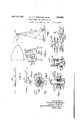
various equivalent devices may be employed Variationsmay be made in many respects without departing from the scope of the in-- vention. v V In the accompanying drawings, forming, a part hereofl which are more or less diagram matic: l Figure "l is a sideelevation of a movable mooring tower with vane control;
Figure 2 is a medial elevation, on a larger scale, of the top of the tower of Figure 1;
Figure 3-is a plan of the control vane of I Figure 1;
Figure l is, a side elevation of the same; Figure 5 is an elevation, ona larger scale,
in SBCtlOIlTOIl line 55of Figure 3;
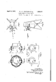
Figure 6 is a plan of details of the samea showing collector rings and wiring diagram, in section on'line 6-60]? Figure 5;
Figure'7 is a side moving means;
Figure-8 is an end-elevation or. the same 7.5 Figure 9 is a plan showing top of mooring elevation of the tower tower and device for controlling movement of tower, actuated by change in position of tail rope; l
Figure 10 is an elevation of the same inkg section on line l010 of F igure-9; i
V Figure 11 is j an elevation like showing a detail. on a largerrscale;
Figure 12 is an elevation in cross-section on line 1212 of Figures 10 and 11; and
Figure 13 is a wiring diagram for the towermooring device shown in Figure 9. r c
Figure 1 shows avmooring tower 9 movable on track 10 and having at its top a vane 410 Figure 1 90 movement oftower19. The wind tends'to maintain the airship 1 always in a position directly to the leeward of a-tower towhich it 1s moored. .For certain purposes, "as for the ing, or, after mooring,- for-settling the ship into a cradle on tracks or bringing-its tail end into proximity to another tower, it may i I of a changed direction of the wind if moored to a single tower, or so that the tail of the ship will be pointed toward that other tower by the wind or so that the ships body will lie over a particular area of ground. As hereinafter explained, this becomes possible by the present invention. Therefore the track 10 may be circular around the base of the tower, merely to face the tower about; or it may be circular about the berth; or circular about another tower.
The upper portion of head tower 9 is shown in greater detail in Figures 2, 3, 4, 5 and 6. The vane 410, revolvable about the central pin 450, carries with it an insulated ring 451 to which are attached current collectors 452. These collectors, on the rotation of the vane 410, make contacts with collector rings 461, which rings are connected by wiring to a source of electrical power 462 and to the motor 463, which serves to move the tower on its track. This motor with its associated mechanism is shown in greater detail in Figures 7 and 8, and may be of any well known and suitable type.
Figure 6 shows diagrammatically a wiring diagram indicating the method of working of this tower-moving device so that, upon the swinging of the vane 410 in either direction, a current is sent through the motor 463 in suitable direction to propel the tower along its track until the face of the tower is in line with the ship, at which position the brushes 452 rest upon the insulation 464 between the two segments 465 which constitute "terminals of motor 463. Figure 5 shows a shield 453 protecting the electrical apparatus from the weather.
This tower moving device may be used on a head tower for maintaining the point of attachment of the rope 80 always on the leeward side of said tower, facing the bow end of the airship. It also may be used ona tail tower for keeping that tower in the direction from the head tower in which the wind is blowing. Figure 2 shows a concave receptacle comprising a funnel-shaped device 421 through which the attachment rope 80 may be led around a sheave 422 and thence downward to the control means 11.
Figures 9, 10, 11, 12 and 13 refer to a means for controlling the movement of a tail mooring tower so as to automatically maintain it in a position directly in the rear of an airship moored thereto. The tower 9, movable on a circular track, has moored the thereto an airship 1 by a rope 80 leading over asheave 12 and thence to a control means net shown. W'hen the tail end of the airship swings to one side, causing its axis to take a position making an angle with the theoretical line joining the centers of the two mooring towers, the tail rope 80 is drawn correspondingly to one side, pressing a pair of floating segmental conductor rings 520 and 510, which are really motor terminals, to that side and into contact with the fixed rings 521 and 511 whose segments at opposite sides are of opposite polarity for delivering current to the motor in one direction or the opposite.
When free, the inner rings 520 and 510 are brought back to their normal position concentric with rings and 511 by means of springs 522 or other equivalent devices. These rings 510, 511 and 520, 521 are insulated and connected by wiring to a source of electric power 462 and to the tower moving motor 463, as indicated in the wiring diagram shown in Figure 13; so that when the inner rings 510, 520 are pressed to either side by the deflection of the connection rope 80, the motor 463 operates automatically as explained below, in whichever direction is needed, to bring the tail tower to a position directly in the rear of the airship 1.
\Vhen this is attained, the circuit is broken at the rings and the motor stops. It will be seen from the diagram of Figure 13 that the movement of rings 510 and 520 to the left, causing contact with the left side of 511 and 521, causes current to flow through the motor in one direction, while the movement of rings 510 and 520 to the right, causing contact with the right half of rings 511 and 521, reverses the direction of flow of the current through the motor, causing it to turn in an opposite direction.
The result obtained by this mechanism is that when the wind causes the airship to move to one side, to the right, for instance, the mooring mast moved in the same direction to a position in the rear of the airship, and when the wind causes the tail of the airship to swing to the left, the mooring mast is moved correspondingly to the left; thus always maintaining the tail mooring tower directly to the rearward of the tail end of the airship.
F i ures 9, 10 and 11 show a bell-shaped mout providing entrance of the attachment rope'80 to its point of attachment with the tower. This bell-shape permits deflection of the rope in all directions without causing damage thereto. The device of Figures 913 can be used as a head mooring tower, if desired, in place of the wind vane apparatus shown in Figures 1-6, in which case the airship itself constitutes a wind vane. On swinging to either side of the predetermined normal relation to the mooring tower, the tower is set in motion to restore its normal relation.
It is thus possible by the present invention to control the relative position of two mooring towers or the relative position of a single mooring tower with respect to some other object. This may be by means of a wind vane or equivalent device, as shown in Figures 1 to 8, inclusive, or by means of the control aption constitutes a division of our copending application Serial No. 502,127, filed September 21, 1921, for Means for mooringv and housing airships. It is intended that the patent to be basedon-thepresent application shall cover, by suitable expression in the appended claims, whatever features of patent'able novelty reside in the disclosure hereincma-de.
We claim:
1. In equipment for mooringairshipa a movable mooring mast and, associated therewith, means responsive to variations in the direction of the wind for moving saidvmooring mast from place to place.
2. In equipment for mooring airships, a rotatable mooring mast, and means respon sive to variations in the direction of the wind for rotating said mooring mast, said means comprising a motor having a wind-vane control; and a flexible connectlon leadmg through a bearing member on said mooring mast to the airship, said'flexible connection pressing against said bearing member upon change of wind direction and thereby cooperating with said motor in rotating said mooring mast.) p a 3. In equipment for mooring an airship, the combination of a, mooring tower and control means therefor actuated bythe variation of the azimuth direction of the longitudinal axis of theairship.
4. In equipment for mooring an airship,
the combination 'of'a tower movable from a 6. In equipment for mooring an airship,
the combination of a tower movable on a way; power means for'moving said: tower;.
and control means for. said power; means actuated by a variation of the azimuth direction vof the longitudinal axis of'the airship.
7 In equipment, for mooring airships, a
V movable mooring mast, and, associated thererotatable mooring mast, and, associated with, means responsive to variations in the position of the airship for moving said mooring masts 8. In equlpment for mooring airships, a
therewith, means responsive to variations in the position of the airship for rotatingsaid mooring v mast.
9. In equipment for mooring airships, a mooring mast movable on a fixed track, pow-- er means for moving said mooring mast on said fixed track, and control means for said power means operating automatically inresponse to variations in the position of the airship relative to the mooring mast.
10. In-equipment for mooringaircraft, a mooring mast provided with means movable about the. axis of the mast for connecting aircraftthereto, and, associated therewith, means responsive to varlatlons 1n the wind 1 for moving said connecting means about said axis.
11. In equipment for mooring an airship, the combination of a mooring tower and con-v trol means for said tower, said control means being actuated by variations in the position; of the connection between thetower and the airship.
12. Control apparatus for a mooring tower foraircraft comprising a' pin disposed on 1 said mooring tower, a wind-responsive member movably mounted on said pin; rings of opposite polarity around said pin; two electrical connecting-brushes, vone for each ring, adaptedto move with said wind-responsive member, each brush having one contact continuously on its own said ring; and a motive power circuit having opposedtermina-ls, each terminal half-surrounding the pin, except that insulation zones separate these ter minals on sides conforming to the wind directionv; the said brushes each having its other contact running on said terminals and insulation zones, whereby the turning of the wind-responsive vmember and its brushes from the insulation zone moves its brushes c to said terminals in the relation which op- 05 erates the motive power and causes the tower to move in the same direction as that in s I which the wind has moved.
13. Control apparatus for a mooring tower means for moving said tower, said flexible connection cooperating with said pow er means in bringing about movement of the tower in response to changes in the di rection of the wind;
Signed at San Bernardino, California, this eleventh dayof November, 1930.
WILFRID V. N, POWELSON. WARREN TRAVELL.
Priority Applications (1)
| Application Number | Priority Date | Filing Date | Title |
|---|---|---|---|
| US523253A US1853081A (en) | 1921-09-21 | 1931-03-17 | Control means for mooring masts |
Applications Claiming Priority (2)
| Application Number | Priority Date | Filing Date | Title |
|---|---|---|---|
| US502127A US1823063A (en) | 1921-09-21 | 1921-09-21 | Means for mooring and housing airships |
| US523253A US1853081A (en) | 1921-09-21 | 1931-03-17 | Control means for mooring masts |
Publications (1)
| Publication Number | Publication Date |
|---|---|
| US1853081A true US1853081A (en) | 1932-04-12 |
Family
ID=27054029
Family Applications (1)
| Application Number | Title | Priority Date | Filing Date |
|---|---|---|---|
| US523253A Expired - Lifetime US1853081A (en) | 1921-09-21 | 1931-03-17 | Control means for mooring masts |
Country Status (1)
| Country | Link |
|---|---|
| US (1) | US1853081A (en) |
Cited By (1)
| Publication number | Priority date | Publication date | Assignee | Title |
|---|---|---|---|---|
| US20170361946A1 (en) * | 2016-06-17 | 2017-12-21 | Wolfgang VON ZEPPELIN | Anchoring vehicle for anchoring an airship at the tail whilst coupled to a mooring-mast at the bow |
-
1931
- 1931-03-17 US US523253A patent/US1853081A/en not_active Expired - Lifetime
Cited By (2)
| Publication number | Priority date | Publication date | Assignee | Title |
|---|---|---|---|---|
| US20170361946A1 (en) * | 2016-06-17 | 2017-12-21 | Wolfgang VON ZEPPELIN | Anchoring vehicle for anchoring an airship at the tail whilst coupled to a mooring-mast at the bow |
| US10427803B2 (en) * | 2016-06-17 | 2019-10-01 | Wolfgang VON ZEPPELIN | Anchoring vehicle for anchoring an airship at the tail whilst coupled to a mooring-mast at the bow |
Similar Documents
| Publication | Publication Date | Title |
|---|---|---|
| US2433344A (en) | Aeronautic positioning device | |
| US1853081A (en) | Control means for mooring masts | |
| US3130945A (en) | Ionocraft | |
| US3611367A (en) | Airborne station for aerial observation system | |
| GB925432A (en) | ||
| US20230271701A1 (en) | Unmanned aerial vehicles energized by power lines | |
| KR102237589B1 (en) | Power supply system for educational or practice drone | |
| RU80821U1 (en) | AEROSTATIC TRANSPORT SYSTEM WITH ELECTRICALLY DRIVED SCREW DRIVES | |
| JPH0224295A (en) | Air flying body connected to ground by wire | |
| US2704193A (en) | Method and apparatus for mooring airships | |
| US1993414A (en) | Aerial signal device | |
| US2649263A (en) | Rotary launching system and apparatus for target aircraft | |
| CN110254714B (en) | Bridge support detection device based on Gemini unmanned aerial vehicle and mobile camera | |
| US1284982A (en) | Process and apparatus for producing and stimulating rainfall. | |
| US2095031A (en) | Automatic steering system for dirigible craft | |
| US2465999A (en) | Wind vane operated control system | |
| US2870383A (en) | Control for apparatus for treating smokestack gases and like effluents | |
| JPH02161173A (en) | In-air staying type wind power type power generator | |
| US2350594A (en) | Airfield traffic control | |
| US1230881A (en) | Aerial apparatus for defense against hostile aircraft and for other purposes. | |
| GB124268A (en) | Improvements in Telescopic Masts. | |
| US1853777A (en) | Method of and apparatus for berthing airships | |
| CN112763789A (en) | Power distribution network electricity testing method and electricity testing robot | |
| US1944448A (en) | Advertising apparatus | |
| GB518068A (en) | Improvements in and relating to wind-operated devices for use in elevated positions for obstructing or destroying hostile aircraft and for other purposes |