US1853024A - Safe casing - Google Patents
Safe casing Download PDFInfo
- Publication number
- US1853024A US1853024A US320970A US32097028A US1853024A US 1853024 A US1853024 A US 1853024A US 320970 A US320970 A US 320970A US 32097028 A US32097028 A US 32097028A US 1853024 A US1853024 A US 1853024A
- Authority
- US
- United States
- Prior art keywords
- casing
- safe
- concrete
- wall
- walls
- Prior art date
- Legal status (The legal status is an assumption and is not a legal conclusion. Google has not performed a legal analysis and makes no representation as to the accuracy of the status listed.)
- Expired - Lifetime
Links
- 239000002184 metal Substances 0.000 description 12
- 210000000038 chest Anatomy 0.000 description 10
- 238000004873 anchoring Methods 0.000 description 5
- 125000006850 spacer group Chemical group 0.000 description 5
- 238000010276 construction Methods 0.000 description 3
- 239000000463 material Substances 0.000 description 3
- 241001494487 Anchon Species 0.000 description 1
- 241000607479 Yersinia pestis Species 0.000 description 1
- 230000015572 biosynthetic process Effects 0.000 description 1
- 238000006073 displacement reaction Methods 0.000 description 1
- 230000000694 effects Effects 0.000 description 1
- 238000000034 method Methods 0.000 description 1
- 238000005192 partition Methods 0.000 description 1
- 238000009877 rendering Methods 0.000 description 1
- 230000000717 retained effect Effects 0.000 description 1
- 238000000926 separation method Methods 0.000 description 1
- 238000003466 welding Methods 0.000 description 1
Images
Classifications
-
- E—FIXED CONSTRUCTIONS
- E05—LOCKS; KEYS; WINDOW OR DOOR FITTINGS; SAFES
- E05G—SAFES OR STRONG-ROOMS FOR VALUABLES; BANK PROTECTION DEVICES; SAFETY TRANSACTION PARTITIONS
- E05G1/00—Safes or strong-rooms for valuables
- E05G1/02—Details
- E05G1/024—Wall or panel structure
Definitions
- l i Wjllith the above and other objects in .VieW that willsbecomeapparent as the natureof the invention; is betternnderstood,wthe saine coning cover;
- Figure 3 is ahorizontalsectional view taken 011 line 33 of Figure. .1, showing th'ecrossed tie rods by dotted lines fextendinglbetweenthe side walls of thelcabinet; V
- Figure tlis a cross-sectional View takenon line of Figure'Q, showing thefiuted. anchor members carried bytheside walls of the cabinet embedded in 'theconcretefilling.
- Figure 5 is a vertical cross-sectional view of the cabinet casing inwhich the safe, structure and safety deposit boxes ;are:adapted tolbeinserted and later filled with concrete;
- 1 igure '6 is a ,bo'ttomplanview of the .cas
- Figure 7 is a cross-sectional View taken on line 77 of' Figure 6;showing the flutedanchor members of the cover depending there- Figure 8 is a fragmentaryfront.elevational view of another formof cabinet casingshow ing another for'inof wall andtop anchoring member withvsupporting shelves for'thegsafe I structure
- Figure 9 is a front elevational view,partly 35 broken away and shown insectionof the.'form o of the connection shown.
- F igureiSV Land FigurelO is'a detail sectional view taken on line 10-10 ofFigur'e 9.
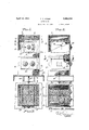
- the casing or form is constructed of co: paratively light weight sheet metal and the preformed top and bottom walls 5 and 6 normally separated from the casing structure are permanently anchored in position to close the upper and lower ends of the casing during the steps taken while placing wall chests or safe structures in the casing.
- the object of this invention is to construct for sale, a metal casing or form into which safe structures of common construction are to be disposed and permanently anchored therein by a concrete filling, the manufactured article of this invention comprising the metal case or form having openings in the front side wall 4 for a wall chest and safety deposit boxes or the like with anchor members upon the inner sides of the form or casing for concrete to be later filled therein.
- top and bottom walls of the casing or form carrying inwardly directed fluted concrete anchor members or strips 7 while similar fluted strips 7a project into the casing or form from the side walls 1 and 2.
- V-shaped members 8 are carried by the side and rear walls of the form adjacent the upper and lower ends thereof as shown in Figures 1, 2 and 5, the upper spacer members 8 centering a wall chest set into the form while the lower spacer members 8 center a partition or compartment wall.
- the vertical walls of the casing or form are braced against bulging action due to the weight of concrete filled therein by the crossed rods 9 extending between the vertical walls, substantially midway the lower and upper ends of the form as illustrated.
- a circular opening 10 is formed in the front wall 4 of the casing or form adj acent its upper end to provide a clearance for mounting a wall chest, while the rectangular opening 11 in the front wall of the casing or form adjacent the lower end thereof accommodates the mounting of the compartment wall 12 in which safety deposit boxes or the like may be placed.
- the forward edge of the compartment wall 12 is secured in any suitable manner to the front wall 4 of the casing or form as by welding, while the V- shaped spacer member 8 associated therewith provides a suitable brace and support at the rear side of the compartment wall 12 as well as at the sides thereof as illustrated in dotted lines in Figure 5.
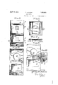
- the metal case or form is set upon a floor or other support 13 and is anchored thereto by the bolt structure 14 engaged with the floor joist 13 and anchoring the threaded boss 16 carried by the bottom wall 6 of the casing or form.
- Concrete or similar plastic material is then poured into the casing or mold to a level adjacent the lower edge of the opening 10 in the front wall 4 of the casing or form, the concrete or similar material completely filling the lower end and surrounding the compartment wall 12 with the anchor members 7 and 7a embedded therein. Bulging of the vertical walls of the casing or form are prevented by the tie rods 9 so that the original shape of the casing or form remains undisturbed.
- a wall chest or other cabinet 17 is then disposed in the casing or form with the front locking door 18 thereof disposed outwardly of the casing or form as illustrated, the chest or safe 17 being centered by the spacer members 8 and is completely surrounded by the concrete filling which rises to the open upper end of the casing or form.
- the cover 5 is then placed in position and the fluted anchor members 7 lowered into the plastic concrete to form tie members holding the cove:- permanently associated with the casing or form.
- a safe deposit box or similar receptacle 19 is inserted in the compartment formed by the wall 12 and is retained therein by the locking mechanism upon the cover plate 20.
- the tie or anchoring member carried by the vertical sides, and the top and bottom walls of the casing or form are of V-shape as indicated by the reference numeral 21 and form a secure anchor when embedded in the concrete.
- a recessed shelf 22 is provided for supporting the opposite ends of the chest or cabinet 17, while shelves 226 are provided for supporting the compartment wall 12.
- FIG. 9 Another form of the invention is shown in Figures 9 and 10, wherein vertical tie and supporting rods 23 extend between the top wall of the compartment wall 1.2 and the upper shelf 22, while crossed tie rods 24 extend between the side walls of the casing or form.
- the article offered for sale and forming the basis of this invention comprises the metal casing or form carrying the concrete anchor members and having openings in the front wall thereof for mounting wall chests or safety deposit boxes.
- the invention further embodies the method of assembly which comprises the pouring of the concrete or other plastic material into the A casing or form and resultingin a structure practically burglar proof and fire proof and being, of a Weight after being set up which i renders the same practically immovable.
- the casing or form constitutes the permanent outer wall of the safe structure and eliminates the necessity of providing special molds and Iotherexpensive devices for embedding Wall chests and other safe structures in a concrete block. All parts of the structure within the case or form are embedded in concrete and separation of any part thereof is rendered extremely difficult and practically impossible. 7
- a safe casing comprising vertical side Q walls, top and bottom walls, separate safe ele-' 25 having closure doors ina side wall of the casing, supports for thesafe elements carried by the side walls, acementitious filling v ments permanently mounted in the casing within the casing surrounding the safe elefments with the latter embedded therein and tie members carried by the side, top and bottom walls and anchored in the cementitious filling with some of the tie. members engaged with the safe elements.
- a safe casing comprising vertical side walls, top andbottom Walls, separate safe n elements permanently mounted in the casing having closure doors in, a sidewall of the casing, supports for the safe elements carried by the side walls, a cementitious filling within the casing surrounding, the safe elements with the latter embedded therein and tie members carried by the side,top and bottom walls and anchored in the cementitious filling with some of the tie members engaged With e the safe elements, the top and bottom walls having edge flanges confined within the side walls. 7
- a safe casing comprising, vertical side walls, top and bottom walls, concrete anchor members extendinginwardly fromsaid side walls, spacer members for safe elements carried by the vertical Walls, 1 shelf members within the casing for supporting safe elements, vertical tie rods between the shelf members. and horizontal tie rods between the sides of the casing.
Landscapes
- Forms Removed On Construction Sites Or Auxiliary Members Thereof (AREA)
Description
April 12, 1932.
T. R. ADAMS SAFE CA'SING F iled Nov. 21, 1928 2 Sheet s-Sheet rlil t u T12 0772 as 1-3, fldama AT RNEY.
April 12, 1932. I R, ADAMS 1,853,024
SAFE CASING Filed Nov. 21, 1928 2 Sheets-Sheet 2 INVENTOR.
7/2523 3. 'fldam is netv -Patented Apr. 12 193 2v pnrnnrc or-ar on riroivmsnornn'nn ADAMS, on sou-TH WILLIAMSBORT; PEST NSYLVANI A Y CASING" I This invention relates to certain new and usefulnnprovements 111 safe casing; andhas for its pr n'iaryob ect toprovide a safe cablnetin the form of'a sheet metal casing into- ;Which relatively small spaced structures: and safetyideposit boxesare adapted to be placed and permanently "anchored therein by a filling=of concrete orthelike poured into the cabinetor casing-structureto completely fill 1 the sameand: s-urroundthe safety cabinet and safety 1 deposit iboxes placed therein for the purpose ofa d ding considerable bulk and weight to; the. completedcabinet structure to minimizeburglarizing the safe deposit cabi- A/further object ofthe; invention isto provide, a sheet metal cabinet orcasing 0f:the desired size-and proportions and :in which I wallsafes and safety deposit'boxesmay be placed and anchored therein byafillinglof concrete or the like, the cabinet or casinglhavingaremova'ble cover. to facilitate, positioning f; the safe and safety deposit box'with' concrete anchoring membersprojecting-into the ,casingsfrom. the: inner walls thereof and also depending from the movable cover so that when the latter is placed into position, the
I same becomes permanently anchored to the I casing as 1 a fixed part thereof while crossed to tie rodsextend between sides of the casing to prevent bulging or lateral displacement there-- of when filled with-concrete. I Astill furtherobject of the'inventioniis to provide a burglarproof-safe casing to receive safe structures and: the'like that are-anchored thereinby a filling of concrete for the protection of the safe structures and 'to i add weight to the safe depositv cabinet to render transporting thereof difficult meansbeingasat) ,sociated' with the' icabinet and floor support a for anchoring; the cabinet to the floor to pre: ventr'removal thereof. l i Wjllith the above and other objects in .VieW that willsbecomeapparent as the natureof the invention; is betternnderstood,wthe saine coning cover;
from
with the presentfinvention, the supporting a floor being shownin. section andlipa'rt, ofi'the cabinet" beingv broken away to illustrate the concrete filling and tie: members for ,anchon o ing the side walls. and top oflthe safetothe concrete filling; V 1 H Figure-21s a side elevational view,l.partly broken away" andshownin section andiillus trating the flooranchorforlthe'safe cabinet;
Figure 3 is ahorizontalsectional view taken 011 line 33 ofFigure. .1, showing th'ecrossed tie rods by dotted lines fextendinglbetweenthe side walls of thelcabinet; V
Figure tlis. a cross-sectional View takenon line of Figure'Q, showing thefiuted. anchor members carried bytheside walls of the cabinet embedded in 'theconcretefilling. c Figure 5 is a vertical cross-sectional view of the cabinet casing inwhich the safe, structure and safety deposit boxes ;are:adapted tolbeinserted and later filled with concrete;
1 igure '6 is a ,bo'ttomplanview of the .cas
Figure 7 is a cross-sectional View taken on line 77 of'Figure 6;showing the flutedanchor members of the cover depending there- Figure 8 is a fragmentaryfront.elevational view of another formof cabinet casingshow ing another for'inof wall andtop anchoring member withvsupporting shelves for'thegsafe I structure i Figure 9is a front elevational view,partly 35 broken away and shown insectionof the.'form o of the connection shown. in F igureiSV; Land FigurelO is'a detail sectional view taken on line 10-10 ofFigur'e 9.,
i As above stated,'the object offthisliliven-o 99 l t on'isto provideia metal cabniet,'a]casing and more; particularly, a metal "form "thatin effect constitutes a permanent concreteinold in which awall or similarsafe 'structureis embedded and the "basic idea lof .this invention is tofprovide such a metal form or mold for v producing 1 a o burglarvproof safe structure. o l/Vhile ade vice'of this charactercanbe used in various connectionst suchooas in homes or oific'es', the same will befound especially adaptable for use in garages and gas service stations in which many burglaries occur. A substantial safe construction is provided by the use of this invention and an inexpensive wall chest in the safe compartment, the concrete filling in the metal case or form rendering the device fire proof and providing sufficient weight to make the completed assembled structure substantially unmovable.
Referring more in detail to the accompanying drawings, and particularly to Figures 1 to 7 there is illustrated a metal casing or form herein shown as being of rectangular formation in cross-section and comprising side walls 1 and 2, a rear wall 3, front wall 4, and top and bottom walls 5 and 6 respectively. The casing or form is constructed of co: paratively light weight sheet metal and the preformed top and bottom walls 5 and 6 normally separated from the casing structure are permanently anchored in position to close the upper and lower ends of the casing during the steps taken while placing wall chests or safe structures in the casing. The object of this invention is to construct for sale, a metal casing or form into which safe structures of common construction are to be disposed and permanently anchored therein by a concrete filling, the manufactured article of this invention comprising the metal case or form having openings in the front side wall 4 for a wall chest and safety deposit boxes or the like with anchor members upon the inner sides of the form or casing for concrete to be later filled therein.
The top and bottom walls of the casing or form carrying inwardly directed fluted concrete anchor members or strips 7 while similar fluted strips 7a project into the casing or form from the side walls 1 and 2. V-shaped members 8 are carried by the side and rear walls of the form adjacent the upper and lower ends thereof as shown in Figures 1, 2 and 5, the upper spacer members 8 centering a wall chest set into the form while the lower spacer members 8 center a partition or compartment wall. The vertical walls of the casing or form are braced against bulging action due to the weight of concrete filled therein by the crossed rods 9 extending between the vertical walls, substantially midway the lower and upper ends of the form as illustrated. A circular opening 10 is formed in the front wall 4 of the casing or form adj acent its upper end to provide a clearance for mounting a wall chest, while the rectangular opening 11 in the front wall of the casing or form adjacent the lower end thereof accommodates the mounting of the compartment wall 12 in which safety deposit boxes or the like may be placed. The forward edge of the compartment wall 12 is secured in any suitable manner to the front wall 4 of the casing or form as by welding, while the V- shaped spacer member 8 associated therewith provides a suitable brace and support at the rear side of the compartment wall 12 as well as at the sides thereof as illustrated in dotted lines in Figure 5.
The metal case or form is set upon a floor or other support 13 and is anchored thereto by the bolt structure 14 engaged with the floor joist 13 and anchoring the threaded boss 16 carried by the bottom wall 6 of the casing or form. Concrete or similar plastic material is then poured into the casing or mold to a level adjacent the lower edge of the opening 10 in the front wall 4 of the casing or form, the concrete or similar material completely filling the lower end and surrounding the compartment wall 12 with the anchor members 7 and 7a embedded therein. Bulging of the vertical walls of the casing or form are prevented by the tie rods 9 so that the original shape of the casing or form remains undisturbed. A wall chest or other cabinet 17 is then disposed in the casing or form with the front locking door 18 thereof disposed outwardly of the casing or form as illustrated, the chest or safe 17 being centered by the spacer members 8 and is completely surrounded by the concrete filling which rises to the open upper end of the casing or form. The cover 5 is then placed in position and the fluted anchor members 7 lowered into the plastic concrete to form tie members holding the cove:- permanently associated with the casing or form. A safe deposit box or similar receptacle 19 is inserted in the compartment formed by the wall 12 and is retained therein by the locking mechanism upon the cover plate 20.
In the form of the invention shown in Figure 8, the tie or anchoring member carried by the vertical sides, and the top and bottom walls of the casing or form are of V-shape as indicated by the reference numeral 21 and form a secure anchor when embedded in the concrete. In this form of the invention, a recessed shelf 22 is provided for supporting the opposite ends of the chest or cabinet 17, while shelves 226 are provided for supporting the compartment wall 12.
Another form of the invention is shown in Figures 9 and 10, wherein vertical tie and supporting rods 23 extend between the top wall of the compartment wall 1.2 and the upper shelf 22, while crossed tie rods 24 extend between the side walls of the casing or form.
From the above detailed description of the invention, it is believed that the construction and operation thereof will at once be apparent, it being noted that the article offered for sale and forming the basis of this invention, comprises the metal casing or form carrying the concrete anchor members and having openings in the front wall thereof for mounting wall chests or safety deposit boxes. The invention further embodies the method of assembly which comprises the pouring of the concrete or other plastic material into the A casing or form and resultingin a structure practically burglar proof and fire proof and being, of a Weight after being set up which i renders the same practically immovable.
The casing or form constitutes the permanent outer wall of the safe structure and eliminates the necessity of providing special molds and Iotherexpensive devices for embedding Wall chests and other safe structures in a concrete block. All parts of the structure within the case or form are embedded in concrete and separation of any part thereof is rendered extremely difficult and practically impossible. 7
While there are herein shown and described the preferred embodiments of the inventi0n,'it is nevertheless to be understood that minor changes may be made therein without departing from the spirit and scope of the invention as claimed.
1; A safe casing comprising vertical side Q walls, top and bottom walls, separate safe ele-' 25 having closure doors ina side wall of the casing, supports for thesafe elements carried by the side walls, acementitious filling v ments permanently mounted in the casing within the casing surrounding the safe elefments with the latter embedded therein and tie members carried by the side, top and bottom walls and anchored in the cementitious filling with some of the tie. members engaged with the safe elements.
2; A safe casing comprising vertical side walls, top andbottom Walls, separate safe n elements permanently mounted in the casing having closure doors in, a sidewall of the casing, supports for the safe elements carried by the side walls, a cementitious filling within the casing surrounding, the safe elements with the latter embedded therein and tie members carried by the side,top and bottom walls and anchored in the cementitious filling with some of the tie members engaged With e the safe elements, the top and bottom walls having edge flanges confined within the side walls. 7
' 3. A safe casing comprising, vertical side walls, top and bottom walls, concrete anchor members extendinginwardly fromsaid side walls, spacer members for safe elements carried by the vertical Walls, 1 shelf members within the casing for supporting safe elements, vertical tie rods between the shelf members. and horizontal tie rods between the sides of the casing.
In testimony'wh'ereof I aflix my signature; a
THOMAS RUTHREN ADAMS.
Priority Applications (1)
| Application Number | Priority Date | Filing Date | Title |
|---|---|---|---|
| US320970A US1853024A (en) | 1928-11-21 | 1928-11-21 | Safe casing |
Applications Claiming Priority (1)
| Application Number | Priority Date | Filing Date | Title |
|---|---|---|---|
| US320970A US1853024A (en) | 1928-11-21 | 1928-11-21 | Safe casing |
Publications (1)
| Publication Number | Publication Date |
|---|---|
| US1853024A true US1853024A (en) | 1932-04-12 |
Family
ID=23248619
Family Applications (1)
| Application Number | Title | Priority Date | Filing Date |
|---|---|---|---|
| US320970A Expired - Lifetime US1853024A (en) | 1928-11-21 | 1928-11-21 | Safe casing |
Country Status (1)
| Country | Link |
|---|---|
| US (1) | US1853024A (en) |
-
1928
- 1928-11-21 US US320970A patent/US1853024A/en not_active Expired - Lifetime
Similar Documents
| Publication | Publication Date | Title |
|---|---|---|
| US2800090A (en) | Earth cooled basement lock box | |
| US3769769A (en) | Permanent basement window frame and pouring buck | |
| US4395861A (en) | Security grid for lighting shafts and the like | |
| US2316712A (en) | Soil retaining wall for basement windows | |
| US3482030A (en) | Underground electrical conductor housing with inner bell-jar housing | |
| ES2085174T3 (en) | PALETTE CONTAINER. | |
| US1853024A (en) | Safe casing | |
| US1056955A (en) | Waterproof burial-vault. | |
| US1982217A (en) | Unit concrete wall construction | |
| US4532870A (en) | Safe apparatus | |
| US1421150A (en) | Fireproof lock box | |
| CN102747748A (en) | Storage battery burying device and burying method for storing storage battery by using same | |
| CN202642531U (en) | Storage battery burying device | |
| US1836814A (en) | Wall safe | |
| US1024527A (en) | Burial-vault. | |
| US1642552A (en) | Safe vault | |
| US3683827A (en) | Loc-blox | |
| JP3507371B2 (en) | Money room | |
| CN221165902U (en) | Lifting device for hydropower installation | |
| CN107419993A (en) | Safety box | |
| US2148689A (en) | Insulated cabinet | |
| US1226747A (en) | Roadway-box. | |
| US2067383A (en) | Lock | |
| US2576232A (en) | Safe construction | |
| US1019925A (en) | Box. |