US1852995A - Hood latch - Google Patents
Hood latch Download PDFInfo
- Publication number
- US1852995A US1852995A US49394730A US1852995A US 1852995 A US1852995 A US 1852995A US 49394730 A US49394730 A US 49394730A US 1852995 A US1852995 A US 1852995A
- Authority
- US
- United States
- Prior art keywords
- closure
- hood
- handle
- parts
- rock shaft
- Prior art date
- Legal status (The legal status is an assumption and is not a legal conclusion. Google has not performed a legal analysis and makes no representation as to the accuracy of the status listed.)
- Expired - Lifetime
Links
Images
Classifications
-
- E—FIXED CONSTRUCTIONS
- E05—LOCKS; KEYS; WINDOW OR DOOR FITTINGS; SAFES
- E05B—LOCKS; ACCESSORIES THEREFOR; HANDCUFFS
- E05B83/00—Vehicle locks specially adapted for particular types of wing or vehicle
- E05B83/16—Locks for luggage compartments, car boot lids or car bonnets
- E05B83/24—Locks for luggage compartments, car boot lids or car bonnets for car bonnets
- E05B83/247—Simultaneously actuated fasteners at separated positions
-
- Y—GENERAL TAGGING OF NEW TECHNOLOGICAL DEVELOPMENTS; GENERAL TAGGING OF CROSS-SECTIONAL TECHNOLOGIES SPANNING OVER SEVERAL SECTIONS OF THE IPC; TECHNICAL SUBJECTS COVERED BY FORMER USPC CROSS-REFERENCE ART COLLECTIONS [XRACs] AND DIGESTS
- Y10—TECHNICAL SUBJECTS COVERED BY FORMER USPC
- Y10S—TECHNICAL SUBJECTS COVERED BY FORMER USPC CROSS-REFERENCE ART COLLECTIONS [XRACs] AND DIGESTS
- Y10S292/00—Closure fasteners
- Y10S292/14—Hood latches
-
- Y—GENERAL TAGGING OF NEW TECHNOLOGICAL DEVELOPMENTS; GENERAL TAGGING OF CROSS-SECTIONAL TECHNOLOGIES SPANNING OVER SEVERAL SECTIONS OF THE IPC; TECHNICAL SUBJECTS COVERED BY FORMER USPC CROSS-REFERENCE ART COLLECTIONS [XRACs] AND DIGESTS
- Y10—TECHNICAL SUBJECTS COVERED BY FORMER USPC
- Y10T—TECHNICAL SUBJECTS COVERED BY FORMER US CLASSIFICATION
- Y10T292/00—Closure fasteners
- Y10T292/08—Bolts
- Y10T292/0801—Multiple
- Y10T292/0848—Swinging
- Y10T292/0849—Operating means
- Y10T292/0853—Link and lever
-
- Y—GENERAL TAGGING OF NEW TECHNOLOGICAL DEVELOPMENTS; GENERAL TAGGING OF CROSS-SECTIONAL TECHNOLOGIES SPANNING OVER SEVERAL SECTIONS OF THE IPC; TECHNICAL SUBJECTS COVERED BY FORMER USPC CROSS-REFERENCE ART COLLECTIONS [XRACs] AND DIGESTS
- Y10—TECHNICAL SUBJECTS COVERED BY FORMER USPC
- Y10T—TECHNICAL SUBJECTS COVERED BY FORMER US CLASSIFICATION
- Y10T292/00—Closure fasteners
- Y10T292/08—Bolts
- Y10T292/1043—Swinging
- Y10T292/1044—Multiple head
- Y10T292/1045—Operating means
Definitions
- hood latch the latch of whichr shalll be positioned within the hood, butwhich shall be operable from the V exterior of the hood.
- kof a simplified and eticient hood latch ofthe above type which shall'be cheap stripteasyA to manufacture and efhcientin servek ice. ⁇ Otherobjects will appear from timey to 11'5 time in the coursey of the ⁇ specification and claims.
- Figure 2 is a section on'V the liner 2 2 of Figuren s s
- a v Figure 3 is a,V section on the linev of Figure l with the parts in different position;
- Figure 4 is' an inside View
- Figure 5' is a section on the line 5f-5 of i.
- abutment portion B4 is positioned substantially within the yplane of the' closure A2 and is inclined upwardly and'inwardlyj in relation thereto.
- C generally Aindicatesa locking rodrotatably mountedv upon the: innerl facev of the closure A2. It maybe mounted, for example, inf the intermediate and terminal bearings C1. It. is herein shown asY having recurved ends 50 C2, .whichv recurvedC ends are adapted to be LATCH.
- D generallyindicatesi a pla-te or base which may be secured' to' the inner faceof the closure A2. Itis centrally apertured as'at D1 and it is provided with brackets D2 D?
- This lever includes an outer arm D5 'which constitutes theI handle outwardly projecting through the slot or aperture and provided with any suitable si, exterior handle member DG.
- inner part or arm D7 of the lever v is connected with said handle and apertured ⁇ as at D8 to' receive the end D10 of a linkV or part D9, the opposite end ofwhich is in rotatable engagement with 8.', the oli-'set or crank portion C10 of the' shaft C.
- This rotatable engagement may be maintained by forming a curved or crooked por. ⁇ tion D11 at the end of the link D9 and closing the path of the crook as by the pin D12.
- the au parts are so proportioned that when the han; dle D6 is positioned linl lock-ing position,the pivotal connection, as at DE, between the arm f D7 and the link D? will'be positioned exterior to a line or plane passing through'the pivotal 95 connection between thelink'D9 andthe crank C10, andthe pivot point D3.
- Figure 2 which shows ythe parts in lockingposition'.
- the result is a: positive locking ⁇ action, as the arm Dhas passed f across the center into locking position and is held there by the spring action of the rod C and the yielding engagement of the offset portions C2 with the inclined abutments B4.
- the length of the lever arm D4 is substantially greater than the length of the central crank offset of the rock shaft C.
- the distance between the points indicated as C and C10 is but a small fraction of the distance between the points indicated as D3 and D1".
- the link D9 represents the long side or hypotenuse of the triangle.
- the distance from C to C1o is far shorter than the distance from D3 to D8.
- the distance from C to C10 ⁇ is about one-third the distance from D3 to D1".
- This proportion of parts will give to the rock shaft a rotation through an arc substantially in excess of the arc through which the handle D5 is rotated, in this particular case the arcs being 110O and 90. respectively.
- a remote control latching device for an automobile hood adapted to draw the lower edge of a double-hinged hood closure downwardly and inwardly into engagement with A the opposed portions of the automobile, which includes a rock shaft mounted on the inner face of the closure for rotation about a generally horizontal axis, cranks at a distance from each other connected with said rock shaft, keepers positioned within said closure for engagement with said cranks, a handle remote from said cranks pivoted on the inner side of said closure, the handle pivot being spaced above the axis of rotation of said rock shaft, said handle projecting on the outside of said closure and movable in a.
- connection from said handle to said rock shaft, said connection made up of parts adapted through their position and arrangement, to, by a single upward movement of said handle in the plane perpendicular to said closure, move said cranks out of engagement with said keepers and substantially out of vertical alignment therewith and move said closure to its open position.
- a remote control latching device for an automobile hood adapted to draw the lower edge of a double-hinged hood closure downwardly and inwardly into engagement with the opposed portions of the automobile, which includes a rock shaft mounted on the inner face of the closure for rotation about a generally horizontal axis, cranks at a distance from each other connected with said rock shaft, keepers positioned Within said on 'nu ot being spaced above the axis of rotation of u said rock shaft, said handle projecting on the outside of said closure and movable ina plane substantially perpendicular to said clo-V sure, a connection from said handle to said rock shaft, said connection made up of parts adapted through their position.
Landscapes
- Lock And Its Accessories (AREA)
- Superstructure Of Vehicle (AREA)
Description
N. A. MEARs April 5, 1932.
HOOD LATCH 2 Sheets-Sheet 1 Filed Nov, 7, 195o @ye/fifa? April 5, 1932.
N. A. MEARS Hoon LATCH Filed Nov. '7, 1930 2 Sheets-Sheet 2 7a w 0 r ,fe ,w @WML f A fmw Mw Patented Apr. 5,l 1932 1 UNirEn stares.
NORTON AfrMEAvRS, OF CHICAGO`,`ILLINOS,
AssieNon To CHICAGO roRGING-ea MANU- FAOTURING- C10.,v 02E"ICHICAGO,` ILLINOIS, A CORPORATION (IEEYIIBLIIVOISl HOOD Application filed November My invention relates-to an improvement in securing means and has for onek purpose the provision of securing means adapted for employmentv toclose the hood of an automobile',
'5" although a like mechanism may be applica- L ble for different purposes. One object of my invention is the provision of a hood latch, the latch of whichr shalll be positioned within the hood, butwhich shall be operable from the V exterior of the hood. Another object is the provision kof a simplified and eticient hood latch ofthe above type which shall'be cheap stripteasyA to manufacture and efhcientin servek ice. `Otherobjects will appear from timey to 11'5 time in the coursey of the` specification and claims.
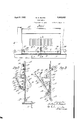
illustrate myl inventionfmore `or less diagrammatically the accompanyingk drawing's, wherein'f'- Figure lisa side elevation;
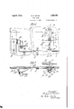
Figure 2is a section on'V the liner 2 2 of Figuren s s A v Figure 3 is a,V section on the linev of Figure l with the parts in different position;
Figure 4 is' an inside View; and
' Figure 5' is a section on the line 5f-5 of i.
- 4i) sion or flange B3 inthe end ofwhich'is an inclinedV abutment portion B4. The abutment portion B4 is positioned substantially within the yplane of the' closure A2 and is inclined upwardly and'inwardlyj in relation thereto. C generally Aindicatesa locking rodrotatably mountedv upon the: innerl facev of the closure A2. It maybe mounted, for example, inf the intermediate and terminal bearings C1. It. is herein shown asY having recurved ends 50 C2, .whichv recurvedC ends are adapted to be LATCH.
7, 1930. Serial N02 493,947.
opposed tothe inclined abutments Bt It will be understood that when the rod C is rotatedin-aiclockwise direction, referring to the position of the parts in Figures 2 and 3,:this rotation causes the'odsetorrecurved portion 55 C2 of the rod to engage the inclined abut .ment member B4, whichy engagement tends to draw the closure A2 downwardly towardthe frame A and inwardly a', ;a"instl the abutment A3. 1 The torsion or spring@ action of the rod 50 provides a yielding locking effect. In normal use this yielding characteristic ofl ther-od is suiiicient to provide enough excess-pressure to compensate for wear.- The rodfis alsopreferably sufficientlyy flexible' to compensate an 05 assembly for variations in size, shape andpo,- sition of parts. Inorder to impart to the rod the necessary rotation, and in order to ypermit its Vcontrol from wi-thout the hood, I provide the follow`v 70 ing structure: D generallyindicatesi a pla-te or base which may be secured' to' the inner faceof the closure A2. Itis centrally apertured as'at D1 and it is provided with brackets D2 D? on each side of saidv aperture, tofwhich 7 brackets may be pivoted, as at D3', the levergenerally indicated as Dt This lever includes an outer arm D5 'which constitutes theI handle outwardly projecting through the slot or aperture and provided with any suitable si, exterior handle member DG. inner part or arm D7 of the lever v is connected with said handle and apertured` as at D8 to' receive the end D10 of a linkV or part D9, the opposite end ofwhich is in rotatable engagement with 8.', the oli-'set or crank portion C10 of the' shaft C. This rotatable engagement may be maintained by forming a curved or crooked por.` tion D11 at the end of the link D9 and closing the path of the crook as by the pin D12. The au parts are so proportioned that when the han; dle D6 is positioned linl lock-ing position,the pivotal connection, as at DE, between the arm f D7 and the link D? will'be positioned exterior to a line or plane passing through'the pivotal 95 connection between thelink'D9 andthe crank C10, andthe pivot point D3. This shall be clearfrom Figure 2 which shows ythe parts in lockingposition'. The result is a: positive locking` action, as the arm Dhas passed f across the center into locking position and is held there by the spring action of the rod C and the yielding engagement of the offset portions C2 with the inclined abutments B4.
The use and operation of my invention are as follows:
In the use of the device it will be understood that when the operator lifts the handle D, its first effect is to break the lock by moving the point DS inwardly in relation to the pivot D3. The rod C is then rotated in counter clockwise direction which frees the offsets C2 from locking engagement with the abutments B4. A further lifting upon the handle D6 is then effective to lift the hood as a whole upwardly from the frame A and upwardly and, if necessary, slightly outwardly from the flange A1". Preferably the parts are so proportioned tha-t= the offsets C2 are rotated substantially out of vertical alignment with the abutments Bt. On returning the hood to closed position, the weight of the hood will keep the parts in unlocked position until the hood itself is lowered as far as it will go. The operator then exerts a positive downward pressure on the handle D6 which serves to rotate the members C2 into locking position against the abutments B4*` and finally to move the arm D7 into the full locking position in which it is shown in Figure 2.
It will be clear from Fig. 3 that the length of the lever arm D4 is substantially greater than the length of the central crank offset of the rock shaft C. Referring to Fig. 3 the distance between the points indicated as C and C10 is but a small fraction of the distance between the points indicated as D3 and D1". In practice I prefer to so proportion the parts that a rotation of the upper or handle member D, D5 about the center D3 through an arc of approximately 90o will rock the rock shaft and its cranks through an are of about 1100. These are the arcs provided for by the structure as .shown in Fig. 3. Withoutlimiting myself precisely to this relationship of arcs or travel of the two parts, I find it a convenient one. In considering the triangle formed by the centers D3, DS and C10, the link D9 represents the long side or hypotenuse of the triangle. Cn the other hand, as above set out, the distance from C to C1o is far shorter than the distance from D3 to D8. In Fig. 3 the distance from C to C10 `is about one-third the distance from D3 to D1". This proportion of parts will give to the rock shaft a rotation through an arc substantially in excess of the arc through which the handle D5 is rotated, in this particular case the arcs being 110O and 90. respectively. As a result I am able to obtain with a relatively small movement of the handle a movement of the rock shaft sufficiently great to obtain the desired contact between the cam surface B4 and the crank C2.
In reference to the cooperation between the members B4 and C2, the rotation of the rock shaft which causes the member C2 to engage the upwardly and inwardly inclined surface B4 effects a camming action which tends to draw the lower edge of the hood both downwardly and inwardly. It is characteristic of this latch that this camming action is obtained by the provision of a free or sliding connection between the members C2 and B4, the crank C2 never reaching a dead or rigid seat against a fixed stop. This permits it to compensate for differences of variations in size, shape and relation of parts, such as Inay arise either in the assembly of the car or in the operation of the car.
It will be realized that whereas I have shown a practical and operative device, nevertheless many changes may be made in size, shape, number and disposition of parts without departingr from the spirit of my invention. I therefore wish my description and drawings to be taken as in a broad sense illustrative and diagrammatic, rather than as limiting me to my precise specification disclosure.
I claim:
1. A remote control latching device for an automobile hood adapted to draw the lower edge of a double-hinged hood closure downwardly and inwardly into engagement with A the opposed portions of the automobile, which includes a rock shaft mounted on the inner face of the closure for rotation about a generally horizontal axis, cranks at a distance from each other connected with said rock shaft, keepers positioned within said closure for engagement with said cranks, a handle remote from said cranks pivoted on the inner side of said closure, the handle pivot being spaced above the axis of rotation of said rock shaft, said handle projecting on the outside of said closure and movable in a. plane substanti ally perpendicular to said closure, a connection from said handle to said rock shaft, said connection made up of parts adapted through their position and arrangement, to, by a single upward movement of said handle in the plane perpendicular to said closure, move said cranks out of engagement with said keepers and substantially out of vertical alignment therewith and move said closure to its open position.
Q. A remote control latching device for an automobile hood adapted to draw the lower edge of a double-hinged hood closure downwardly and inwardly into engagement with the opposed portions of the automobile, which includes a rock shaft mounted on the inner face of the closure for rotation about a generally horizontal axis, cranks at a distance from each other connected with said rock shaft, keepers positioned Within said on 'nu ot being spaced above the axis of rotation of u said rock shaft, said handle projecting on the outside of said closure and movable ina plane substantially perpendicular to said clo-V sure, a connection from said handle to said rock shaft, said connection made up of parts adapted through their position. and arrallge-` ment, to, by a single upward movement of said handle in the pla-ne substantially perpendicular to said closure, move said cranksV out of engagement with said keepers and substantially out of vertical alignment therewithV and move said closure rto its open position,l and by a reverse movement of said handle in said plane perpendicular tol said closure to move said Closure to its closed position and move said cranks into locking engagement With said keepers.
Signed at Chicago, county ofl Cook. and l State of Illinois, this 4th day of November,
NORTON A. MEARS.
Priority Applications (1)
| Application Number | Priority Date | Filing Date | Title |
|---|---|---|---|
| US49394730 US1852995A (en) | 1930-11-07 | 1930-11-07 | Hood latch |
Applications Claiming Priority (1)
| Application Number | Priority Date | Filing Date | Title |
|---|---|---|---|
| US49394730 US1852995A (en) | 1930-11-07 | 1930-11-07 | Hood latch |
Publications (1)
| Publication Number | Publication Date |
|---|---|
| US1852995A true US1852995A (en) | 1932-04-05 |
Family
ID=23962378
Family Applications (1)
| Application Number | Title | Priority Date | Filing Date |
|---|---|---|---|
| US49394730 Expired - Lifetime US1852995A (en) | 1930-11-07 | 1930-11-07 | Hood latch |
Country Status (1)
| Country | Link |
|---|---|
| US (1) | US1852995A (en) |
Cited By (1)
| Publication number | Priority date | Publication date | Assignee | Title |
|---|---|---|---|---|
| US2837363A (en) * | 1953-07-09 | 1958-06-03 | Gen Motors Corp | Latching mechanism |
-
1930
- 1930-11-07 US US49394730 patent/US1852995A/en not_active Expired - Lifetime
Cited By (1)
| Publication number | Priority date | Publication date | Assignee | Title |
|---|---|---|---|---|
| US2837363A (en) * | 1953-07-09 | 1958-06-03 | Gen Motors Corp | Latching mechanism |
Similar Documents
| Publication | Publication Date | Title |
|---|---|---|
| GB1302310A (en) | ||
| US1852995A (en) | Hood latch | |
| US3988801A (en) | Lifting mechanism for sliding doors | |
| US2084677A (en) | Door safety device | |
| US2198161A (en) | Lock for double-hung windows | |
| US1949645A (en) | Door operating mechanism | |
| US1592406A (en) | Door latch | |
| US1506925A (en) | Operating mechanism for garage and barn doors | |
| US1114350A (en) | Dump-car. | |
| US1469352A (en) | Door-locking mechanism | |
| US1235381A (en) | Gate. | |
| US1814510A (en) | Closure operator | |
| US1041864A (en) | Door-operating device. | |
| US955537A (en) | Flush-car-door supporting and operating means. | |
| US1177471A (en) | Door-opener. | |
| US535008A (en) | Safety elevator-lock | |
| US1538103A (en) | Automatic door or gate | |
| US937101A (en) | Dump-door-operating mechanism. | |
| US1883173A (en) | Door closing device | |
| US1256934A (en) | Door-latch. | |
| US437115A (en) | Transom lifter | |
| US1110944A (en) | Door-hanger. | |
| US253810A (en) | Swinging gate | |
| US1219716A (en) | Door opening and closing device. | |
| US1815123A (en) | Closure operator |