US1852986A - Two-cycle motor - Google Patents
Two-cycle motor Download PDFInfo
- Publication number
- US1852986A US1852986A US409888A US40988829A US1852986A US 1852986 A US1852986 A US 1852986A US 409888 A US409888 A US 409888A US 40988829 A US40988829 A US 40988829A US 1852986 A US1852986 A US 1852986A
- Authority
- US
- United States
- Prior art keywords
- piston
- cylinder
- central part
- air inlet
- exhaust port
- Prior art date
- Legal status (The legal status is an assumption and is not a legal conclusion. Google has not performed a legal analysis and makes no representation as to the accuracy of the status listed.)
- Expired - Lifetime
Links
- 238000001816 cooling Methods 0.000 description 3
- 239000000956 alloy Substances 0.000 description 2
- 229910045601 alloy Inorganic materials 0.000 description 2
- 239000007789 gas Substances 0.000 description 2
- 101150039167 Bex3 gene Proteins 0.000 description 1
- XAGFODPZIPBFFR-UHFFFAOYSA-N aluminium Chemical compound [Al] XAGFODPZIPBFFR-UHFFFAOYSA-N 0.000 description 1
- 229910052782 aluminium Inorganic materials 0.000 description 1
- 239000004411 aluminium Substances 0.000 description 1
- 150000001768 cations Chemical class 0.000 description 1
- 230000000295 complement effect Effects 0.000 description 1
- 230000000694 effects Effects 0.000 description 1
- 239000000203 mixture Substances 0.000 description 1
- 230000005855 radiation Effects 0.000 description 1
- 230000002000 scavenging effect Effects 0.000 description 1
Images

Classifications
-
- F—MECHANICAL ENGINEERING; LIGHTING; HEATING; WEAPONS; BLASTING
- F01—MACHINES OR ENGINES IN GENERAL; ENGINE PLANTS IN GENERAL; STEAM ENGINES
- F01P—COOLING OF MACHINES OR ENGINES IN GENERAL; COOLING OF INTERNAL-COMBUSTION ENGINES
- F01P1/00—Air cooling
- F01P1/06—Arrangements for cooling other engine or machine parts
Definitions
- the present invention relates to two stroke case in the event of an over-high pressure de-' engines of the type-in which theburnt gases velopingf'in the exhaust, which over-high escape through ports uncovered by the pispressure may be. accidental orideterinined ton'at the end of its outstrok-e, and the ex and'momentary or permanent.
- Fig. 1 illustrates a preferred embodiment aboutits center. Therefrom results a more. of my invention given by way of example; equal distribution of the cooling action and Fig. 2 shows a modified form of piston; accessorily butveryadvantageously of lubri- Fig. 3 is another embodiment of a piston cation and wear. 8 is a piston ring. Head according to my invention; and i 2is centered in the mortise 9 of the body, and Fig. 4 shows still another embodiment.
- I utilize, on the contrary, the suction proas previously stated, through exhaust ports, 99 p 'duced by the exhaust, either through me- 19 located ingthe lower part of the cylinder chanical means or :by the mere effect of the and thatrthe air inlet for this purpose is inertia of the gases projected into the exeffected through opening-s located in the cylhaust pipe.
- I may also utilize a combination inder head and controlled by a slide valve let of these means. or in any'other suitable manner.
- a two stroke engine comprising a cylinder, provided with an exhaust port, a crankcase rovided with an air inlet, and means for circulating cold air from said air inlet into said exhaust port during the intervals of time between exhausts.
- a two stroke engine comprising a cylinder provided with an exhaust port, a crankcase provided with an air inlet, and means for circulating cold air from said air inlet into said exhaust port during the interval between the end of the instroke and the begining of the outstroke.
- a two stroke engine comprising :1 cylinder provided with an exhaust port, a crankcase provided with an air inlet, a piston in said cylinder adapted to uncover said exhaust port and place it in direct communication with the crankcase air inlet during the intervals of time between exhausts, whereby cold air can be circulated from said air inlet into said exhaust port during said intervals.
- a two stroke engine comprising a cylinder provided with an exhaust port, a crankcase provided with an air inlet, a piston in said cylinder adapted to uncover said exhaust port and place it in direct communication with the crankcase air inlet during the interval between the end of the instroke and the beginning of the outstroke, whereby cold air can be circulated from said air inlet into said exhaust port during said interval.
- a piston comprising a central part, means for connecting said central part to the connecting rod, two separate cylindrical elements having each a relatively small height with respect to the distance between them and being adapted to fit against the walls of the cylinder, a conical web for connecting the upper cylindrical element to the central part and a conical web provided with apertures for connecting the lower cylindrical element to the central part.
- a piston comprising a central part, a ball and socket joint for connecting said central part to the connecting rod, two separate cylindrical elements having each a relatively small height with respect to the distance between them and being adapted to fit against the walls of the cylinder, a conical web for connecting the upper cylindrical element to the central part and a conical web provided with apertures for connecting the lower cylindrical element to the central part.
- a piston comprising a central part provided with longitudinal conduits, a ball and socket joint for connecting said central part to the connecting rod, two separate cylindrical elements having each a relatively small height with respect to the distance between them and the walls of the cylinder, a conical web provided with apertures for connecting the lower cylindrical element to the central part, whereby air can circulate through said conduits and apertures so as to cool the piston.
Landscapes
- Engineering & Computer Science (AREA)
- Chemical & Material Sciences (AREA)
- Combustion & Propulsion (AREA)
- Mechanical Engineering (AREA)
- General Engineering & Computer Science (AREA)
- Cylinder Crankcases Of Internal Combustion Engines (AREA)
Description
April 5, 1932.- E. H. TARTRAIS 1,352,936
TWO-CYCLE MOTOR Filed Nov. 26, 1929 2 Sheets-Sheet 1 Fig. 1
[UE'IHU E. H. TARTRAIS TWO-CYCLE MOTOR April 5, 1932.
2 Sheets-Sheet 2 Filed NOV. 26, 1929 I m u Patented Apr.-5, 1932. 7 1 52 9 UNI ED: STAT PATENT- OFFICE EUGENE HENRI ZIA'RTRAIS, or MONTMORENCY, FRANCE- Two-C CLE MOTOR, V Application filed November. 26,1929, Serial, No. 409,888 and in France November 26, 1928. I c
The present inventionrelates to two stroke case in the event of an over-high pressure de-' engines of the type-in which theburnt gases velopingf'in the exhaust, which over-high escape through ports uncovered by the pispressure may be. accidental orideterinined ton'at the end of its outstrok-e, and the ex and'momentary or permanent.
5 plosive mixture enters the cylinder through In order to improve the cooling of the pisan inlet valve located in the opposite portion ton and atthe same time of the whole engine, of said cylinder. 7 it, is. advantageous to use "the special shapes My invention consists in" causing cold'air hereinafter described; i to enter the crankcase and to circulate there In the form showninFig. 2it will be seen i 10 from directly into said exhaust, ports which that the piston is composed of a body 1 having are, for this purpose, uncovered by the pisthe shape of a sheave, which may be made'of a ton during the intervals of time between the light conducting alloy and'a head 2 prefer-V. exhausts, in order to 0001 not only the crankably' nade of a heat resisting and slightly case and the parts connected thereto, but also conducting, alloy. In the example shown, 1 the'lower part of the cylinders and the pis said head is maintained in suitable position tons. 1 V I byia central rod 3 provided. with a nutl My invention also comprises special forms and awasher 5. 6 is the articulation of the I of pistons adapted to improve the operation connecting rod little end with the piston.
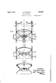
of the engine. Said articulation consists-of a ball and socket 20 In the drawings joint'in orderto allow of the piston turning 4 Fig. 1 illustrates a preferred embodiment aboutits center. Therefrom results a more. of my invention given by way of example; equal distribution of the cooling action and Fig. 2 shows a modified form of piston; accessorily butveryadvantageously of lubri- Fig. 3 is another embodiment of a piston cation and wear. 8 is a piston ring. Head according to my invention; and i 2is centered in the mortise 9 of the body, and Fig. 4 shows still another embodiment. certain play is provided between 2 and 9 so Adverting to Fig.1, 18 is the cylinder proas to permit said head 2 to expand freely; vided with exhaustiports 19. The piston 20 Consequently'very little heat will be transis shown at its upper dead point. Said pis I mitted from head to body 1 through the- 30 ton is short enough to uncover the exhaust "small surface of contact 10, and in order to ports duringa sufficient interval of time. All do away with heat'radiation, a screen such aperture 21 is provided in crankcase 22 so as 11 consisting of a thin sheet of aluminium that cold air may enter through said open? for .exampleis disposed under the head, as the ing and circulate as shown by the arrows. presentembodimentconcerns an engine in 35 Said air is introduced in any suitable manwhich self ignitionis not.to be feared. In
ner, for instance by means of a fan or merely order to ensurethe cooling of body 1 I have under the eflect of the wind when the engine provided holes 25 of the largest possible seeis fitted on a body moving at a highspeed such tion in the conical surface 12. Furthermore as-an aircraft for instance. Or still better it is pointed out that scavenging takes place,
I utilize, on the contrary, the suction proas previously stated, through exhaust ports, 99 p 'duced by the exhaust, either through me- 19 located ingthe lower part of the cylinder chanical means or :by the mere effect of the and thatrthe air inlet for this purpose is inertia of the gases projected into the exeffected through opening-s located in the cylhaust pipe. I may also utilize a combination inder head and controlled by a slide valve let of these means. or in any'other suitable manner. In the case of the mere efiect of inertia It willtherefore appear that when the pis being utilized for producingthe air eircuton is in the middle part of-its stroke,'as lation, I may advantageously fit inlet port shown in Fig.1 2, if-there is a difl'erence'of- 21 with a check or automatic valve 23 in order pressure between the crankcase and the: ex- V toprevent exceptional backfire in the'crankhaust: pipe, air will circulate as shown by 1001 the arrows, and cool webs 12 and 13 of the body through convection, and the remainder of the pieces through conduction.
In the embodiment of Fig. 3 it is proposed to cool the head of the piston as completely as possible. To that end I provide holes such as 14, establishing communication between the opposite cones of the piston. Air therefore follows the path shown by arrows 15 and directly cools the piston head, which in this case is shown as being integral with the bodv. I could obviously at the same time provide other holes such as 16 (Fig. 3) disposed in the same way as the holes 25 in Fig. 2, if it is deemed advantageous to obtain a complementary circulation according to arrows 17 of Fig. 3, which circulation is identical to that described with reference to Fig. 2.
Finally I may, when utilizing the piston head shown in Fig. 2, cool the inner wall of the upper cone and nut 11. In this case I make use of the arrangement shown in Fig. 4, which is a combination of the above described arrangements and needs no further explainhat I claim is:
1. A two stroke engine comprising a cylinder, provided with an exhaust port, a crankcase rovided with an air inlet, and means for circulating cold air from said air inlet into said exhaust port during the intervals of time between exhausts.
2. A two stroke engine comprising a cylinder provided with an exhaust port, a crankcase provided with an air inlet, and means for circulating cold air from said air inlet into said exhaust port during the interval between the end of the instroke and the begining of the outstroke.
3. A two stroke engine comprising :1 cylinder provided with an exhaust port, a crankcase provided with an air inlet, a piston in said cylinder adapted to uncover said exhaust port and place it in direct communication with the crankcase air inlet during the intervals of time between exhausts, whereby cold air can be circulated from said air inlet into said exhaust port during said intervals.
4. A two stroke engine comprising a cylinder provided with an exhaust port, a crankcase provided with an air inlet, a piston in said cylinder adapted to uncover said exhaust port and place it in direct communication with the crankcase air inlet during the interval between the end of the instroke and the beginning of the outstroke, whereby cold air can be circulated from said air inlet into said exhaust port during said interval.
5. In a two stroke engine as claimed in claim 3, a piston comprising a central part, means for connecting said central part to the connecting rod, two separate cylindrical elements having each a relatively small height with respect to the distance between them and being adapted to fit against the walls of the cylinder, a conical web for connecting the upper cylindrical element to the central part and a conical web provided with apertures for connecting the lower cylindrical element to the central part.
6. In a two stroke engine as claimed in claim 3, a piston comprising a central part, a ball and socket joint for connecting said central part to the connecting rod, two separate cylindrical elements having each a relatively small height with respect to the distance between them and being adapted to fit against the walls of the cylinder, a conical web for connecting the upper cylindrical element to the central part and a conical web provided with apertures for connecting the lower cylindrical element to the central part.
7 In a two stroke engine as claimed in claim 3, a piston comprising a central part provided with longitudinal conduits, a ball and socket joint for connecting said central part to the connecting rod, two separate cylindrical elements having each a relatively small height with respect to the distance between them and the walls of the cylinder, a conical web provided with apertures for connecting the lower cylindrical element to the central part, whereby air can circulate through said conduits and apertures so as to cool the piston.
In testimony whereof I have signed this specification.
EUGENE HENRI TARTRAIS.
being adapted to fit against 1-
Applications Claiming Priority (1)
| Application Number | Priority Date | Filing Date | Title |
|---|---|---|---|
| FR1852986X | 1928-11-26 |
Publications (1)
| Publication Number | Publication Date |
|---|---|
| US1852986A true US1852986A (en) | 1932-04-05 |
Family
ID=9681669
Family Applications (1)
| Application Number | Title | Priority Date | Filing Date |
|---|---|---|---|
| US409888A Expired - Lifetime US1852986A (en) | 1928-11-26 | 1929-11-26 | Two-cycle motor |
Country Status (1)
| Country | Link |
|---|---|
| US (1) | US1852986A (en) |
Cited By (1)
| Publication number | Priority date | Publication date | Assignee | Title |
|---|---|---|---|---|
| US4195600A (en) * | 1976-04-15 | 1980-04-01 | Yamaha Hatsudoki Kabushiki Kaisha | Crankcase chamber compression type two cycle internal combustion engines |
-
1929
- 1929-11-26 US US409888A patent/US1852986A/en not_active Expired - Lifetime
Cited By (1)
| Publication number | Priority date | Publication date | Assignee | Title |
|---|---|---|---|---|
| US4195600A (en) * | 1976-04-15 | 1980-04-01 | Yamaha Hatsudoki Kabushiki Kaisha | Crankcase chamber compression type two cycle internal combustion engines |
Similar Documents
| Publication | Publication Date | Title |
|---|---|---|
| US2067049A (en) | Internal combustion engine | |
| US2451271A (en) | V-type internal-combustion engine | |
| US2254439A (en) | Internal combustion engine | |
| US1763625A (en) | Piston for internal-combustion engines | |
| US1852986A (en) | Two-cycle motor | |
| US2497781A (en) | Forced draft air-cooling system for internal-combustion engines | |
| US3160148A (en) | Internal combustion engine | |
| US1924188A (en) | Rotary valve for internal combustion engines | |
| US2332105A (en) | Barrel engine | |
| US1622717A (en) | Two-cycle internal-combustion engine | |
| JPH0613861B2 (en) | Two-cycle engine piston | |
| US1871589A (en) | Internal combustion engine | |
| US1472549A (en) | Internal-combustion engine | |
| US2383648A (en) | Internal-combustion engine | |
| US1355451A (en) | Internal-combustion engine | |
| US1653253A (en) | Piston | |
| US1639165A (en) | Internal-combustion engine | |
| US1804010A (en) | Two cycle internal combustion engine swash plate construction | |
| US1447127A (en) | Internal-combustion engine | |
| US1015502A (en) | Explosive-engine. | |
| US2410229A (en) | Miniature gasoline engine | |
| US1841119A (en) | Internal combustion engine | |
| US1468962A (en) | Internal-combustion engine | |
| US2966887A (en) | High temperature piston engines | |
| US1501393A (en) | Internal-combustion engine |