US1852971A - Waterless gas holder - Google Patents
Waterless gas holder Download PDFInfo
- Publication number
- US1852971A US1852971A US303288A US30328828A US1852971A US 1852971 A US1852971 A US 1852971A US 303288 A US303288 A US 303288A US 30328828 A US30328828 A US 30328828A US 1852971 A US1852971 A US 1852971A
- Authority
- US
- United States
- Prior art keywords
- gas
- gas holder
- sealing
- closure member
- waterless
- Prior art date
- Legal status (The legal status is an assumption and is not a legal conclusion. Google has not performed a legal analysis and makes no representation as to the accuracy of the status listed.)
- Expired - Lifetime
Links
- 238000007789 sealing Methods 0.000 description 13
- 239000007788 liquid Substances 0.000 description 9
- 238000012856 packing Methods 0.000 description 4
- 230000005484 gravity Effects 0.000 description 2
- 239000000463 material Substances 0.000 description 2
- 229910001018 Cast iron Inorganic materials 0.000 description 1
- 240000000491 Corchorus aestuans Species 0.000 description 1
- 235000011777 Corchorus aestuans Nutrition 0.000 description 1
- 235000010862 Corchorus capsularis Nutrition 0.000 description 1
- 229910000746 Structural steel Inorganic materials 0.000 description 1
- 239000011286 gas tar Substances 0.000 description 1
- 238000007689 inspection Methods 0.000 description 1
- 239000010985 leather Substances 0.000 description 1
- 238000005096 rolling process Methods 0.000 description 1
- 239000010913 used oil Substances 0.000 description 1
- XLYOFNOQVPJJNP-UHFFFAOYSA-N water Substances O XLYOFNOQVPJJNP-UHFFFAOYSA-N 0.000 description 1
Images

Classifications
-
- F—MECHANICAL ENGINEERING; LIGHTING; HEATING; WEAPONS; BLASTING
- F17—STORING OR DISTRIBUTING GASES OR LIQUIDS
- F17B—GAS-HOLDERS OF VARIABLE CAPACITY
- F17B1/00—Gas-holders of variable capacity
- F17B1/02—Details
- F17B1/04—Sealing devices for sliding parts
-
- F—MECHANICAL ENGINEERING; LIGHTING; HEATING; WEAPONS; BLASTING
- F17—STORING OR DISTRIBUTING GASES OR LIQUIDS
- F17B—GAS-HOLDERS OF VARIABLE CAPACITY
- F17B1/00—Gas-holders of variable capacity
- F17B1/013—Gas-holders of variable capacity with movables discs
Definitions
- This invention relates to improvements in gas holders, especially those provided with a disc-like closure member.
- the present invention aims to obviate this drawback, and provides a closing device of a very good stability and reliability;
- the closureV member is disc-shaped, or preferably dishshaped, adapted to contain a certain quantity of ballasting liquid therein, and has a ballasting weight disposed at the centre thereof, all composed in such a manner that the centre of gravity of they entire movable system is sit- Y uated at a certain appreciable distance verti- CII cally downwardly of the centre of the buoyancy resultingl from the total upward pressure of theV gas, which fact enables the closure member to assume the equilibrium position of its own accord, and insures a very reliable guiding thereof.
- the closure member is formed to a flat circular receptacle or container, the bottom of which is shaped'in an inverted shallow cone, at the centre of which isattacheda housing to accommodate ballasting weights and also means to regulate the amount of the ballastingliquid in the receptacle is provided in the housing.
- the invention also comprises a novel means of sealing with the aid' of a sealingliquid, such as oil, to effectively prevent the least possible leakage along the periphery ofthe disc-shaped closure member.
- a sealingliquid such as oil
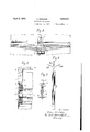
- Figure 1 is a vertical longitudinal sectional view through a gas holder provided 4witha closure member according to my invention, parts being shown in elevation,
- Figure 2 is an enlarged vertical sectional view of the closure member
- Figure 3 is an enlarged vertical sectional view of the sealing device
- Figure 4 is an enlarged longitudinal sectional view of the telescopic conducting device of the sealing liquid.
- Figure 5 is an enlargedfragmentary longitudinal section takeny through the line V-V of Figure 2.
- l is ay gas'holder orreservoir, preferably of the cylindrical type, supported byy the truss structure 2.H 3 is la disc-like closingkmember movable vertically in the. gas holder 1.
- This closure member 3 is formed like a shallow vessel, open upwardly, with the lateral wall 4 and the bottom wall 5 shaped like an inf verted funnel kand reinforced by annular ribs 6.
- a housing or chamber 7 Centrally of the bottom 5 and depending therefrom is a housing or chamber 7 for accommodating weights 8 of any suitablel material, such as cast iron or lead, calculatedapproximately Ito give the predetermined'pressure to the gas in the reservoir 1.
- the disc-like closure member 3 is adapted to hold a certain amount of ballasting liquid 9.v To regulate .the amount of the liquid, a
- valve 10 is provided over the top portion of the'hou'sing 7, controllable with the aid of the handle l1'associated with the valve rod 12 ( Figures 2 andq).
- the valve 10 When the valve 10 is opened, a portion of water in the member 3 flows into the exit tube 13 through the port 14, and then to the interior of the housing 7 going out of it through ythe overflow holes 15 and falling onto the bottom of 'they reservoir and collecting to thepool 1,6, to be finally led to the well 17 throughthe underground pipe 18;V
- a packing piece 21 which Ymaybe made of any suitable material such as felt, jute or leather for eX-v 100 ⁇ ample, is securely held at a portion thereof by being pinched between the wooden block 19 and a web portion of the channel 20, the remaining portion of the packing piece is allowed to extend over the inner surface of the wall of the gas holder l, being held straight by a supporting member, such as angle iron 22.
- the downwardly depending portion of the lower one of the two packing pieces will tend to Yflare outwardly and stick to the wall oi' the gas holder due to the pressure of the gas acting on it, which fact further insures a very close sealing. It is preferable that two of the sealing devices such as just described be disposed one over the other.
- the free space left over the uppermost sealing device and lying between the wall of the gas holder and the lateral wall of the closure member constitutes an annular channel for the sealing liquid.
- the sealing liquid which may be oil or any other suitable liquid such as gas-tar, is supplied to the supply pipe 2l provided outside of the gas holder.
- rlhe pipe 24 is held rigid by bars .238 secured to the roof, as shown in Figs. l and el.
- This pipe 24.- is connected Wit-hin the roo' of the truss work to the top of a combination oil pipe 25 consisting of component pipes olf varying diameters and sliding telescopically one within the other.
- Thisl telescopic oil conduit opens at a small tube 2G attached to the lowermost end thereof to a short sleeve 27, which is in turn connected at the bottom thereof to a plurality of radially disposed small ⁇ pipes 28 ending at a horizontal nozzle 29, from which oil flows in jets, producing an annular body of the sealing liquid along the channel 23.
- the sealing device above described By means of the sealing device above described the least possible leakage of gas in the reservoir is avoided. rlhe oil that oozes out of the lower-most packing piece flows down along the wall of the gas holder and collects in the annular channel 30, from which the used oil may be pumped out, properly cleaned and heated, if desired, and may again be circulated through the sealing system.
- the combination pipe 25 Will contract and dilate like a telescope and yet insures a perfect joint. IVhen the closure disc comes to its lowermost position, it will ride over the seat-s 3l provided along the periphery of the bottom of the reservoir. If
- the closure dise 3 may be provided with a circumferential platform 32 for the sake of inspection.
- the disc-shaped closure device according to my invention floating on a volume of gas with its centre of gravity far underneath the centre of buoyancy, is very stable and is guided in a very reliable manner, and the sealing means insures a perfeet sealing, the least conceivable leakage of the gas being avoided.
Landscapes
- Engineering & Computer Science (AREA)
- Mechanical Engineering (AREA)
- General Engineering & Computer Science (AREA)
- Filling Or Discharging Of Gas Storage Vessels (AREA)
Description
April 5, 4193.2.
Z. ISHIKAWA WATERLESS GAS HOLDER Filed Aug. 51, '1928 2 Sheets-Sheet l Ej, l.
im ml In vena/1'l Znzp By 5W( AO/'716] y April 5, 1932- z. lsHlKAwA 1,852,971 K WATERLESS GA$ HOLDERv Filed Aug. 3l, 1928 2 Sheets-Sheet 2 In ven [or: Zenzo Z6/71, [/awa Patented: Apr; 5, 7,1932.
kFIVE?ENTI GFFICE4 ZENZO ISHIKAWA, OF YOKOHVAMA, ,JAPAN 'WATERLESS` GAS .HOLDER Application filed August 31, 1928. Serial No. 303,288.
This invention relates to improvements in gas holders, especially those provided with a disc-like closure member.
In a waterless gasjholder with a discshaped closure member guided by rollers disposed vertically and rolling along the inner surface of the wall Vof the gas holder, the distance between the upper and the lower guide rollers cannot be very much increased owing ,to the fact that it inevitably lessens the available height of the reservoir. Consequently the closurel member is liable totilt,
"leadingto the leakage of gas.
The present invention aims to obviate this drawback, and provides a closing device of a very good stability and reliability;
According to my invention the closureV member is disc-shaped, or preferably dishshaped, adapted to contain a certain quantity of ballasting liquid therein, and has a ballasting weight disposed at the centre thereof, all composed in such a manner that the centre of gravity of they entire movable system is sit- Y uated at a certain appreciable distance verti- CII cally downwardly of the centre of the buoyancy resultingl from the total upward pressure of theV gas, which fact enables the closure member to assume the equilibrium position of its own accord, and insures a very reliable guiding thereof.
In al` practical embodiment o the invention, the closure member is formed to a flat circular receptacle or container, the bottom of which is shaped'in an inverted shallow cone, at the centre of which isattacheda housing to accommodate ballasting weights and also means to regulate the amount of the ballastingliquid in the receptacle is provided in the housing.
The invention also comprises a novel means of sealing with the aid' of a sealingliquid, such as oil, to effectively prevent the least possible leakage along the periphery ofthe disc-shaped closure member.
In the accompanying drawings, which show one embodiment of the invention:
Figure 1 is a vertical longitudinal sectional view through a gas holder provided 4witha closure member according to my invention, parts being shown in elevation,
Figure 2 is an enlarged vertical sectional view of the closure member,
Figure 3 is an enlarged vertical sectional view of the sealing device,
Figure 4 is an enlarged longitudinal sectional view of the telescopic conducting device of the sealing liquid, and
.Figure 5 is an enlargedfragmentary longitudinal section takeny through the line V-V ofFigure 2. n l
ReferringV more particularly to the nur` merals of reference on the drawings, lis ay gas'holder orreservoir, preferably of the cylindrical type, supported byy the truss structure 2.H 3 is la disc-like closingkmember movable vertically in the. gas holder 1. This closure member 3 is formed like a shallow vessel, open upwardly, with the lateral wall 4 and the bottom wall 5 shaped like an inf verted funnel kand reinforced by annular ribs 6. Centrally of the bottom 5 and depending therefrom is a housing or chamber 7 for accommodating weights 8 of any suitablel material, such as cast iron or lead, calculatedapproximately Ito give the predetermined'pressure to the gas in the reservoir 1.
Vith an object of varying the gas pressure and enabling anaccurate adjustment thereof, the disc-like closure member 3 is adapted to hold a certain amount of ballasting liquid 9.v To regulate .the amount of the liquid, a
valve 10 is provided over the top portion of the'hou'sing 7, controllable with the aid of the handle l1'associated with the valve rod 12 (Figures 2 andq). When the valve 10 is opened, a portion of water in the member 3 flows into the exit tube 13 through the port 14, and then to the interior of the housing 7 going out of it through ythe overflow holes 15 and falling onto the bottom of 'they reservoir and collecting to thepool 1,6, to be finally led to the well 17 throughthe underground pipe 18;V
Outside of and valong the lateralwall4 4 of` the closing member 3 is secured through the 05 intermediary of channelfiron 20 a wooden block 19v which serves to guide the vertical y motion of the closure member 3. A packing piece 21, which Ymaybe made of any suitable material such as felt, jute or leather for eX-v 100` ample, is securely held at a portion thereof by being pinched between the wooden block 19 and a web portion of the channel 20, the remaining portion of the packing piece is allowed to extend over the inner surface of the wall of the gas holder l, being held straight by a supporting member, such as angle iron 22. The downwardly depending portion of the lower one of the two packing pieces will tend to Yflare outwardly and stick to the wall oi' the gas holder due to the pressure of the gas acting on it, which fact further insures a very close sealing. It is preferable that two of the sealing devices such as just described be disposed one over the other. The free space left over the uppermost sealing device and lying between the wall of the gas holder and the lateral wall of the closure member constitutes an annular channel for the sealing liquid.
The sealing liquid, which may be oil or any other suitable liquid such as gas-tar, is supplied to the supply pipe 2l provided outside of the gas holder. rlhe pipe 24 is held rigid by bars .238 secured to the roof, as shown in Figs. l and el. This pipe 24.- is connected Wit-hin the roo' of the truss work to the top of a combination oil pipe 25 consisting of component pipes olf varying diameters and sliding telescopically one within the other. Thisl telescopic oil conduit opens at a small tube 2G attached to the lowermost end thereof to a short sleeve 27, which is in turn connected at the bottom thereof to a plurality of radially disposed small `pipes 28 ending at a horizontal nozzle 29, from which oil flows in jets, producing an annular body of the sealing liquid along the channel 23.
By means of the sealing device above described the least possible leakage of gas in the reservoir is avoided. rlhe oil that oozes out of the lower-most packing piece flows down along the wall of the gas holder and collects in the annular channel 30, from which the used oil may be pumped out, properly cleaned and heated, if desired, and may again be circulated through the sealing system.
As the closure dise goes up and down in the gas holder, the combination pipe 25 Will contract and dilate like a telescope and yet insures a perfect joint. IVhen the closure disc comes to its lowermost position, it will ride over the seat-s 3l provided along the periphery of the bottom of the reservoir. If
` desired, the closure dise 3 may be provided with a circumferential platform 32 for the sake of inspection.
As above described the disc-shaped closure device according to my invention, floating on a volume of gas with its centre of gravity far underneath the centre of buoyancy, is very stable and is guided in a very reliable manner, and the sealing means insures a perfeet sealing, the least conceivable leakage of the gas being avoided.
and controlling means to regulate the quantity of the ballasting liquid in said container. In testimony whereof I atlix my signature.
ZENZO ISHIKAIVA.
Priority Applications (1)
| Application Number | Priority Date | Filing Date | Title |
|---|---|---|---|
| US303288A US1852971A (en) | 1928-08-31 | 1928-08-31 | Waterless gas holder |
Applications Claiming Priority (1)
| Application Number | Priority Date | Filing Date | Title |
|---|---|---|---|
| US303288A US1852971A (en) | 1928-08-31 | 1928-08-31 | Waterless gas holder |
Publications (1)
| Publication Number | Publication Date |
|---|---|
| US1852971A true US1852971A (en) | 1932-04-05 |
Family
ID=23171364
Family Applications (1)
| Application Number | Title | Priority Date | Filing Date |
|---|---|---|---|
| US303288A Expired - Lifetime US1852971A (en) | 1928-08-31 | 1928-08-31 | Waterless gas holder |
Country Status (1)
| Country | Link |
|---|---|
| US (1) | US1852971A (en) |
Cited By (2)
| Publication number | Priority date | Publication date | Assignee | Title |
|---|---|---|---|---|
| US2559137A (en) * | 1946-12-11 | 1951-07-03 | Hollandsche Constructie Werkpl | Dry gasholder having a ballast actuated piston |
| US2596066A (en) * | 1948-04-14 | 1952-05-06 | Stacey Bros Gas Construction C | Gasholder |
-
1928
- 1928-08-31 US US303288A patent/US1852971A/en not_active Expired - Lifetime
Cited By (2)
| Publication number | Priority date | Publication date | Assignee | Title |
|---|---|---|---|---|
| US2559137A (en) * | 1946-12-11 | 1951-07-03 | Hollandsche Constructie Werkpl | Dry gasholder having a ballast actuated piston |
| US2596066A (en) * | 1948-04-14 | 1952-05-06 | Stacey Bros Gas Construction C | Gasholder |
Similar Documents
| Publication | Publication Date | Title |
|---|---|---|
| US1852971A (en) | Waterless gas holder | |
| US2437125A (en) | Floating roof for tanks | |
| US1628635A (en) | Storage apparatus | |
| US649610A (en) | Acetylene-gas generator. | |
| GB470071A (en) | Improvements in or relating to gas and/or liquid storage devices | |
| US2236996A (en) | Breather reservoir of the gas holder type | |
| US115684A (en) | Improvement in the manufacture of pneumatic gas | |
| US997313A (en) | Drinking-fountain. | |
| US2397846A (en) | Apparatus for analysis of gas | |
| US1081982A (en) | Milk-can filler. | |
| US872359A (en) | Automatic measuring-tank. | |
| US73073A (en) | Improved apparatus for carbureting | |
| US974756A (en) | Registering mechanism. | |
| US1564854A (en) | Closure for dry gasometers | |
| US429042A (en) | Telfokd macneill | |
| US1179695A (en) | Instrument for recording water-levels. | |
| US1124432A (en) | Gas-analysis apparatus. | |
| US95412A (en) | Improved apparatus for carbtjretting air and gas | |
| US1002680A (en) | Garment-marking device. | |
| US604199A (en) | thorn | |
| US1052748A (en) | Device for filling bottles or other receptacles with liquids. | |
| FR2268457A1 (en) | Vertically spaced plant containers - has pillars supporting containers with soil held above water | |
| US613689A (en) | Acetylene-gas generator | |
| US777431A (en) | Fertilizer-dropper. | |
| US989306A (en) | Acetylene-gas generator. |