US1852958A - Internal combustion engine - Google Patents
Internal combustion engine Download PDFInfo
- Publication number
- US1852958A US1852958A US372451A US37245129A US1852958A US 1852958 A US1852958 A US 1852958A US 372451 A US372451 A US 372451A US 37245129 A US37245129 A US 37245129A US 1852958 A US1852958 A US 1852958A
- Authority
- US
- United States
- Prior art keywords
- casing
- engine
- internal combustion
- valve
- combustion engine
- Prior art date
- Legal status (The legal status is an assumption and is not a legal conclusion. Google has not performed a legal analysis and makes no representation as to the accuracy of the status listed.)
- Expired - Lifetime
Links
- 238000002485 combustion reaction Methods 0.000 title description 17
- 238000001816 cooling Methods 0.000 description 11
- 239000000314 lubricant Substances 0.000 description 5
- 238000005266 casting Methods 0.000 description 3
- 239000000203 mixture Substances 0.000 description 3
- 238000010276 construction Methods 0.000 description 1
- 238000005461 lubrication Methods 0.000 description 1
- 238000004519 manufacturing process Methods 0.000 description 1
- 238000012856 packing Methods 0.000 description 1
- 239000004576 sand Substances 0.000 description 1
Images

Classifications
-
- F—MECHANICAL ENGINEERING; LIGHTING; HEATING; WEAPONS; BLASTING
- F01—MACHINES OR ENGINES IN GENERAL; ENGINE PLANTS IN GENERAL; STEAM ENGINES
- F01L—CYCLICALLY OPERATING VALVES FOR MACHINES OR ENGINES
- F01L7/00—Rotary or oscillatory slide valve-gear or valve arrangements
- F01L7/02—Rotary or oscillatory slide valve-gear or valve arrangements with cylindrical, sleeve, or part-annularly shaped valves
- F01L7/021—Rotary or oscillatory slide valve-gear or valve arrangements with cylindrical, sleeve, or part-annularly shaped valves with one rotary valve
- F01L7/023—Cylindrical valves having a hollow or partly hollow body allowing axial inlet or exhaust fluid circulation
Definitions
- My invention relates to internal combustion enginesand more particularly to those of the rotary sleevevalve type.
- An objectof the present invention is toprovide alight, comparatively silent air-cooledv engine which is positive in operation and which reduces the number of small moving parts to a minimum.
- the invention provides an air cooling system embodying a hood which embraces the usual fan and upper part of the motor and
- An additional object of the invention resides in the provision of a lubrication system wherein the valve casing is provlded with a main lubricant bore having communication with the interior of the casing at various points to supply lubricant to the valve and leads to other rotatable parts of the engine such as the generator gearing.
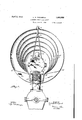
- Figure 1 is .an end elevation of an internal combustion engine constructed in accordance with my invention
- Fig.2 is a side elevation'of the same; and showing half of the cooling or ventilating hood removed;
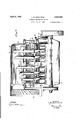
- FIG. 3 is a vertical sectional view taken on the line -3-3 of Fig. 2;
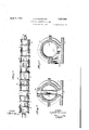
- Fig.,4t is a fragmentarydetail viewpartly in elevation and partlyin section;
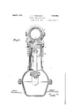
- Fig.5 is a horizontal sectional view taken on substantially the line 55 of Fig. 4;
- Fig.7 is a vertical sectiontaken on substantially the line7"7 of Fig. 2;
- Fig. 8 is a similar view taken on'line 8-8 of Fig. 25
- Fig. 9 is an enlarged fragmentary longi-.
- Fig. 10 is a fragmentarybottom plan view of the valve casing.
- Fig. 11 is an enlarged detail view illustrat mg the fan belt adprstmg means.
- aninternal combustion engine having vertical cylinders 5 in which reciprocatory pistons 6 arearranged is provided.
- A. hollow rotary valve 10 is rotatably mounted within the casing and is equipped with stub shafts 11 at its ends and which project laterally therefrom and are journaled in the end walls of the casing as at 12. At a point centrally of its ends the valve is'provided with a plurality of spaced inlet ports 13 to receive combustible mixture from suitable carbureter.
- the valve is provided with a'set of intake and exhaust ports designated atl and- 15, respectively, and which are adapted to communicate withthe cylinder 5 at predetermined times by way of intakes and exhaust openings 16 and 1'? provided in the plate 8.
- Annular packing rings or ribs 18 are formed on the valve uponopposite sides of the port therein and are revoluble in circumferential grooves formed upon the interior of the valve casing. As particularly illustrated inFigs4 ing21 formed in the plate Sand communicating with one of the ports 15.
- Each two exhaust ports 15 and 16 are diametrically opposed and are connected by a rectangular conduit 20 extendingtransversely through the valve and is adapted to establish communication between exhausts outlets 21 in the valve.
- the valve casing is formed with a laterally extending hollow casting 22 at a point in transverse alignment with the intakes 13.
- the outer end of this casting is adapted to be connected with a suitable carbureter. It follows that combustible mixture flowing into the hollow casting 22 will pass through the openings 13 and pass longitudinally through the valve in opposite directions and it is conducted to the various cylinders through the intake ports above referred to.
- one side of the casing is formed with a longitudinally extending lubricant bore 23 having lateral branches 2% which open into the grooves 1.9.
- a branch 25 extends from the bore 23 to one of the stub shafts 11.
- the valve casing is formed with a vertically extending bore 26 which communicates with the adjacent end of the bore 23 and opens into the upper end of a casing 27 in which the shaft 28 of a suitable primer 29 is mounted, the latter being driven through gearing 30.
- a gear housing 31 is arranged along the casing 27 and housesithe gears 32 of a vertical generator 33.
- a drain pipe 34 extends from the gear housing 31 through the crank case of the engine and con ducts all surplus lubricant from the rotatable parts in the casings 26 and 31 back to the crank case.
- the invention also provides a cooling or ventilating structure which consists of a horizontally arranged circular casing which extends the entire length of the engine and embraces the engine head and cylinders.
- This casing consists of semi-circular sections 35 having flanges 36 at their ends which are secured together by transverse fastenings 37.
- the forward end of the casing is open and is of such diameter as to receive the usual ventilating fan 37a which is driven from a fan belt 38.
- the rear ends of the sections have depending vertical portions 39 which are curved laterally toward each other to hold the casing at this end.
- the casing is supported on the enginebyaninverted V-shaped bracket 38 which is mounted on and arises from the forward end of the valve casing and has its upper end secured between the flanges 36.
- the lower longitudinal edges of the sections extend a considerable distance along the upper ends of the cylinders and are secured to the latter by transverse bolts 40 passing between the cylinders and engaged with the opposed portions of the sections.
- each of these distributors is formed with a pair of depending side wings 42 extending down along the opposite sides of its corresponding cylinder in spaced relation thereto as disclosed in Fig. 1. The lower ends of these side wings are attached to the engine block by transverse fastenings 43.
- valve casing is formed with circumferential cooling fins 4-5 and the cylinders are provided with similar fins 46.
- An exhaust manifold 47 is arranged upon the upper section of the valve casing and communicates with the exhaust ports therein. Longitudinally aligned openings 47a are provided in the deflectors through which the exhaust manifold 47 extends.
- a casing to embrace the upper portion of an engine, a plurality of vertically disposed substantially circular deflectors of concavo-convex cross section of graduated diameters supported on said engine within the casing, each of said deflectors having a cut out portion for the rece tion of the upper portion of said engine an having depending wing portions formed at either side of said out out portion for straddling said engine, and fastening means extending through said wing portions.
- a cooling device for internal combustion engines comprising a vertically disposed substantially circular concave-convex member air deflector adapted to be supported on the upper portion of an internal combustion engine with its convex face facing forwardly, and a pair of depending attaching flanges formed on the lower edge of the deflector, ar-
- a cooling attachment for internalconibustion engines comprising a substantially circular dish shaped memberhaving a cut out portion at one side thereof, and extending wing portions formed at either side of sa1d cut out portion. 7 c
- a casing enclosing the upper portion of said engine and forming a passage therearound, and a plurality of vertically disposed deflector plates mounted upon said engine within said passage, said reflector plates hang of increasing area from the front to the rear of said engine and having depending side wings extending downwardly at each side of said engine.
- an air cooling apparatus for internal combustion engines having longitudinally arranged cylinders, an elongated casing enclosmg said cylinders and forming an air passage therearound, said casing being open at the 7 forward end and partially closed at the rearward end for deflecting air downwardly over the rear end of said engine, and a plurality of longitudinally spaced vertically disposed deflector plates mounted upon said engine of an internal combustion engine and to form a longitudinally extending air passage therearound, a plurality of upstanding concavoconvex air deflecting members supported on said engine in longitudinally spaced relation within said casing, said air deflecting members being of graduated diameters and arranged with the smallest member adjacent the forward end of said casing, each of said air deflecting members having a wing depending from the lower edge thereof at each side of said engine, said wings being disposed between adjacent cylinders of said engine.
Landscapes
- Engineering & Computer Science (AREA)
- Mechanical Engineering (AREA)
- General Engineering & Computer Science (AREA)
- Cylinder Crankcases Of Internal Combustion Engines (AREA)
Description
April 1932- L. M. DODAMEAD 1,852,958
INTERNAL COMBUSTION ENG INE .Filed June 20, 1929 6 Sheets-Sheet l lNVENTOR WITNESS 7 L.M,Doc[nmao ATTORNEY April 1932. M. DODAMEAD 1,852,958
I NTERNAL COMBUSTION ENGINE Filed June 20, 1929 6 Sheets-Sheet 2 INVENTOR WiTNESS 1, .12 flodam mmaa.
ATTORNEY Aprils, 1932. I M. D-ODAMEAD INTERNAL COMBUSTION ENGINE Filed June 20, 1929 6 Sheets-Sheet 3 ATTORNEY April 5, 1932. L. M DODAMEAD INTERNAL COMBUSTION ENGINE Filed June 20, 1929 6 Sheets-Sheet 4 INVENTOR l dlladnueazi WITNESS qmsedzw fi ATTORNEY April 5, 1932.
L. M DODAMEAD INTERNAL COMBUSTION ENGINE Filed June 20, 1929 ATTORNEY 6Sheets-Sheet 5 April5, 1932. M. DODAMEAD INTERNAL COMBUSTION ENGINE Filed June 20, 1929 6 Sheets-Sheet 6 M x. 152% Eg INVENTOR ATTORNEY w. as A; Lg 4 Sill-2::
Elan-E; g
7 p UMQED sr Patented Apr. 5 1932 .aLLOYI) MQDODAMEAQOF' NORFOLK, VIRGINIA INTERNAL COMBUSTION ENGINE Application filed June 20,
- My invention relates to internal combustion enginesand more particularly to those of the rotary sleevevalve type.
An objectof the present invention is toprovide alight, comparatively silent air-cooledv engine which is positive in operation and which reduces the number of small moving parts to a minimum.
Further the invention provides an air cooling system embodying a hood which embraces the usual fan and upper part of the motor and An additional object of the invention resides in the provision of a lubrication system wherein the valve casing is provlded with a main lubricant bore having communication with the interior of the casing at various points to supply lubricant to the valve and leads to other rotatable parts of the engine such as the generator gearing.
With the precedingand other objects and advantages in mind, the invention consists in the novel combination of elements, constructions and arrangements of parts and operationsto be hereinafter more fully described, claimed and illustrated in the accompanying drawings, wherein:
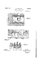
Figure 1 is .an end elevation of an internal combustion engine constructed in accordance with my invention;
Fig.2 is a side elevation'of the same; and showing half of the cooling or ventilating hood removed;
*Fig. 3 isa vertical sectional view taken on the line -3-3 of Fig. 2;
" Fig.,4t is a fragmentarydetail viewpartly in elevation and partlyin section;
. Fig.5 is a horizontal sectional view taken on substantially the line 55 of Fig. 4;
6 is an elevation ofthe rotary valve embodied in the invention;
- Fig.7 is a vertical sectiontaken on substantially the line7"7 of Fig. 2; Fig. 8 is a similar view taken on'line 8-8 of Fig. 25
1929. Serial mevaasr;
Fig. 9 is an enlarged fragmentary longi-. I
tudinally sectional view of the valve and surrounding valve casing;
Fig. 10 is a fragmentarybottom plan view of the valve casing; and
Fig. 11 is an enlarged detail view illustrat mg the fan belt adprstmg means.
Referring to the invention in detail aninternal combustion engine having vertical cylinders 5 in which reciprocatory pistons 6 arearranged is provided. Extending longitudi- I nally of the engine 'is'a circular two-part valve casing 7 the lower part of which is formed with a rectangular plate 8 which is secured to the upper ends of the cylinders by suitable fastenings 9. A. hollow rotary valve 10 is rotatably mounted within the casing and is equipped with stub shafts 11 at its ends and which project laterally therefrom and are journaled in the end walls of the casing as at 12. At a point centrally of its ends the valve is'provided with a plurality of spaced inlet ports 13 to receive combustible mixture from suitable carbureter. For eachcylinder 5 the valve is provided with a'set of intake and exhaust ports designated atl and- 15, respectively, and which are adapted to communicate withthe cylinder 5 at predetermined times by way of intakes and exhaust openings 16 and 1'? provided in the plate 8. Annular packing rings or ribs 18 are formed on the valve uponopposite sides of the port therein and are revoluble in circumferential grooves formed upon the interior of the valve casing. As particularly illustrated inFigs4 ing21 formed in the plate Sand communicating with one of the ports 15. Each two exhaust ports 15 and 16 are diametrically opposed and are connected bya rectangular conduit 20 extendingtransversely through the valve and is adapted to establish communication between exhausts outlets 21 in the valve. casing and corresponding exhaust openings 17 in the plate 8 when the valve is in the position disclosed in Fig. 7 It will thus be seen that each half revolution brings one of each pair of intake ports 14 and 15 in registration with the corresponding intakes 16 in the plate 8 and that the exhaust conduits reach exhaust position subsequent to each closing of one of these ports 14 and 15.
In order to supply combustible mixture to the rotary valve, the valve casing is formed with a laterally extending hollow casting 22 at a point in transverse alignment with the intakes 13. The outer end of this casting is adapted to be connected with a suitable carbureter. It follows that combustible mixture flowing into the hollow casting 22 will pass through the openings 13 and pass longitudinally through the valve in opposite directions and it is conducted to the various cylinders through the intake ports above referred to.
For the purpose of supplying lubricant to the rotatable valve one side of the casing is formed with a longitudinally extending lubricant bore 23 having lateral branches 2% which open into the grooves 1.9. At one end of the valve casing a branch 25 extends from the bore 23 to one of the stub shafts 11. At its rear end the valve casing is formed with a vertically extending bore 26 which communicates with the adjacent end of the bore 23 and opens into the upper end of a casing 27 in which the shaft 28 of a suitable primer 29 is mounted, the latter being driven through gearing 30. A gear housing 31 is arranged along the casing 27 and housesithe gears 32 of a vertical generator 33. A drain pipe 34 extends from the gear housing 31 through the crank case of the engine and con ducts all surplus lubricant from the rotatable parts in the casings 26 and 31 back to the crank case.
The invention also provides a cooling or ventilating structure which consists of a horizontally arranged circular casing which extends the entire length of the engine and embraces the engine head and cylinders. This casing consists of semi-circular sections 35 having flanges 36 at their ends which are secured together by transverse fastenings 37. As particularly illustrated in Fig. 2 the forward end of the casing is open and is of such diameter as to receive the usual ventilating fan 37a which is driven from a fan belt 38. The rear ends of the sections have depending vertical portions 39 which are curved laterally toward each other to hold the casing at this end. The casing is supported on the enginebyaninverted V-shaped bracket 38 which is mounted on and arises from the forward end of the valve casing and has its upper end secured between the flanges 36. The lower longitudinal edges of the sections extend a considerable distance along the upper ends of the cylinders and are secured to the latter by transverse bolts 40 passing between the cylinders and engaged with the opposed portions of the sections.
In order to distribute the air passing rearwardly in the casing from the van to the various cylinders a plurality of circular concavo-convex air deflectors 41 is provided. These deflectors 41 are graduated in diameter and are arranged with the smallest one adjacent the frame. Each air deflector is positioned between two adjacent cylinders and has an eccentric opening which receives the valve casing. The lower end of each of these distributors is formed with a pair of depending side wings 42 extending down along the opposite sides of its corresponding cylinder in spaced relation thereto as disclosed in Fig. 1. The lower ends of these side wings are attached to the engine block by transverse fastenings 43. Inasmuch as the deflectors are of graduated diameters some of the air from the fan 37 will strike each of the deflectors and be discharged downwardly around the cylinders. To further aid the cooling of the engine the valve casing is formed with circumferential cooling fins 4-5 and the cylinders are provided with similar fins 46.
An exhaust manifold 47 is arranged upon the upper section of the valve casing and communicates with the exhaust ports therein. Longitudinally aligned openings 47a are provided in the deflectors through which the exhaust manifold 47 extends.
With reference to the cooling or ventilating system it follows that the air drawn into the forward end of the casing 35 is carried rearwardly to the casing where it strikes the deflectors 41. By reason of the dished or concave configuration of the deflectors the air is deflected downwardly over the respective cylinders.
lVhat is claimed is:
1. In an air cooling apparatus for internal combustion engines, a casing to embrace the upper portion of an engine, a plurality of vertically disposed substantially circular deflectors of concavo-convex cross section of graduated diameters supported on said engine within the casing, each of said deflectors having a cut out portion for the rece tion of the upper portion of said engine an having depending wing portions formed at either side of said out out portion for straddling said engine, and fastening means extending through said wing portions.
2. A cooling device for internal combustion engines comprising a vertically disposed substantially circular concave-convex member air deflector adapted to be supported on the upper portion of an internal combustion engine with its convex face facing forwardly, and a pair of depending attaching flanges formed on the lower edge of the deflector, ar-
ranged on either side of said engine and adapted to be detachably secured to the en-c gine block.
3; As an article of manufacture, a cooling attachment for internalconibustion engines comprising a substantially circular dish shaped memberhaving a cut out portion at one side thereof, and extending wing portions formed at either side of sa1d cut out portion. 7 c
4. In an air cooling apparatus for internal combustion engines, a casing enclosing the upper portion of said engine and forming a passage therearound, and a plurality of vertically disposed deflector plates mounted upon said engine within said passage, said reflector plates hang of increasing area from the front to the rear of said engine and having depending side wings extending downwardly at each side of said engine.
5; In an air cooling apparatus for internal combustion engines having longitudinally arranged cylinders, an elongated casing enclosmg said cylinders and forming an air passage therearound, said casing being open at the 7 forward end and partially closed at the rearward end for deflecting air downwardly over the rear end of said engine, and a plurality of longitudinally spaced vertically disposed deflector plates mounted upon said engine of an internal combustion engine and to form a longitudinally extending air passage therearound, a plurality of upstanding concavoconvex air deflecting members supported on said engine in longitudinally spaced relation within said casing, said air deflecting members being of graduated diameters and arranged with the smallest member adjacent the forward end of said casing, each of said air deflecting members having a wing depending from the lower edge thereof at each side of said engine, said wings being disposed between adjacent cylinders of said engine.
LLOYD M. DODAMEAD
Priority Applications (1)
| Application Number | Priority Date | Filing Date | Title |
|---|---|---|---|
| US372451A US1852958A (en) | 1929-06-20 | 1929-06-20 | Internal combustion engine |
Applications Claiming Priority (1)
| Application Number | Priority Date | Filing Date | Title |
|---|---|---|---|
| US372451A US1852958A (en) | 1929-06-20 | 1929-06-20 | Internal combustion engine |
Publications (1)
| Publication Number | Publication Date |
|---|---|
| US1852958A true US1852958A (en) | 1932-04-05 |
Family
ID=23468170
Family Applications (1)
| Application Number | Title | Priority Date | Filing Date |
|---|---|---|---|
| US372451A Expired - Lifetime US1852958A (en) | 1929-06-20 | 1929-06-20 | Internal combustion engine |
Country Status (1)
| Country | Link |
|---|---|
| US (1) | US1852958A (en) |
Cited By (1)
| Publication number | Priority date | Publication date | Assignee | Title |
|---|---|---|---|---|
| US20080210191A1 (en) * | 2006-12-28 | 2008-09-04 | Dirker Martin W | Cylinder head arrangement including a rotary valve |
-
1929
- 1929-06-20 US US372451A patent/US1852958A/en not_active Expired - Lifetime
Cited By (2)
| Publication number | Priority date | Publication date | Assignee | Title |
|---|---|---|---|---|
| US20080210191A1 (en) * | 2006-12-28 | 2008-09-04 | Dirker Martin W | Cylinder head arrangement including a rotary valve |
| US7802550B2 (en) * | 2006-12-28 | 2010-09-28 | Caterpillar Inc | Cylinder head arrangement including a rotary valve |
Similar Documents
| Publication | Publication Date | Title |
|---|---|---|
| US1852958A (en) | Internal combustion engine | |
| US1838974A (en) | Internal combustion engine | |
| US1782389A (en) | Rotary valve | |
| US1625597A (en) | Forced-feed internal-combustion engine | |
| US1875444A (en) | Internal combustion engine | |
| US2253505A (en) | Engine | |
| US1995935A (en) | Super-charger for internal combustion engines | |
| US2288017A (en) | Internal combustion engine | |
| US1293279A (en) | Internal-combustion engine. | |
| US1398354A (en) | wright | |
| US1997119A (en) | Internal combustion rotary motor | |
| US1629664A (en) | Internal-combustion engine | |
| US1503821A (en) | Combined exhaust and intake manifold | |
| US1970025A (en) | Charge forming device | |
| US2021204A (en) | Engine scavenging system | |
| US1433762A (en) | Rotatable pump for cooling systems of automobiles | |
| US1730731A (en) | Mixer for internal-combustion engines | |
| US1552415A (en) | Gasoline engine | |
| US1586909A (en) | Crank-case cooler for motor vehicles | |
| USRE17692E (en) | Fuel and exhaust-gas contbol device fob engines | |
| US1578111A (en) | Internal-combustion engine | |
| US2660156A (en) | Internal-combustion engine with scavenging air blower | |
| US1975863A (en) | Heater for motor vehicles | |
| US1466783A (en) | Internal-combustion engine | |
| US1320776A (en) | And one-twelfth to charles j |