US1852946A - Burner for autogenous fusing and welding under water - Google Patents
Burner for autogenous fusing and welding under water Download PDFInfo
- Publication number
- US1852946A US1852946A US469594A US46959430A US1852946A US 1852946 A US1852946 A US 1852946A US 469594 A US469594 A US 469594A US 46959430 A US46959430 A US 46959430A US 1852946 A US1852946 A US 1852946A
- Authority
- US
- United States
- Prior art keywords
- burner
- fusing
- heating
- pipes
- oxygen
- Prior art date
- Legal status (The legal status is an assumption and is not a legal conclusion. Google has not performed a legal analysis and makes no representation as to the accuracy of the status listed.)
- Expired - Lifetime
Links
Images
Classifications
-
- F—MECHANICAL ENGINEERING; LIGHTING; HEATING; WEAPONS; BLASTING
- F23—COMBUSTION APPARATUS; COMBUSTION PROCESSES
- F23D—BURNERS
- F23D14/00—Burners for combustion of a gas, e.g. of a gas stored under pressure as a liquid
- F23D14/38—Torches, e.g. for brazing or heating
- F23D14/44—Torches, e.g. for brazing or heating for use under water
Definitions
- the warming surface at the fusing-place is limited by the protectives around the heatingfiame, thereby causing the material which is to be fused, to be warmed through only according to the size of the warming-surface at the fusing-place.
- the object of the present invention is to avoid all these drawbacksby gasification of liquid fuel within a plurality of gasifyingchambers by means of electric heating appliances and by conducting these gases out of the gasifying chambers into an accumulating, chamber which is connected with a number of new'oxygen supply-pipes corresponding with the number of heating-nozzles.
- the fusing-oxygen conducted, asusual, to Q a central nozzle.
- the addition ofoxygen to the ready gas-mixture is to be rendered unnecessary by arranging the single parts of the burner mouth-piece in sucha way as to form ring-channels amongst each otherin which a heatable and ignitible, gas-mixture is produced which, vwithout fear of interrupting the flame of the burner mouth-piece, can emanate from the with any increase of pressure.
- Fig. l is a side-view ofthe'first form of constructingthe burner. r I
- Fig. 2 is a longitudinal section of a devel- V opment of the burner.- t Fig; 13 shows the second form in which the burner-handle is represented in development, 7
- valves 9 h, i By the opening of valves 9 h, i the oxygen streams through pipes 15, u, v and further through pipes f, g, h into the heating-nozzles
- the fusing-oxygen after opening valve 8, streams through a pipe i into the fusing-nozzle (1.
- a safety-valve 2 opens and closes automatically when overpressure is caused through evaporization in the heating-chamber k.
- the oxygen-pipes s, 9 h i are supplied out of branch-pipes from an oxygen supplyconduit not shown in drawings, in which a relief-valve is arranged. Into the conduit for supplying liquid fuel to pipe 10 a reliefvalve is also provided.
- the burner-head is provided with bores separate from each other and widened at their upper end for reception of the oxygen-supply pipes i, t, u, v and the fuel supply pipes m, n, 0.
- the single parts a, b, c, d of the complex burner mouth-piece are screwed on to the actual burner-head 0, so as to form ring-channels in which the oxygen and the gases, so far conducted entirely separate from each other, can mix.
- the single part-s of the burner mouth-piece are provided with trusses B against which the gases and the oxygen beat, thereby causing a whirl and a good mixture.
- the supply currents can be regulated.
- 1, 1 1 1 are the gas-developers from which the gases stream into the accumulator 1.
- 0 d 6 f are exchangeable insertioncores provided with asbestos insulation for reception of residues from the development of gas.
- y are electric heat-radiators.
- a safety-valve 2 opens and closes automatically when overpressure occurs through evaporization in the heating-chamber In.
- a burner for the autogenous cutting and welding under water comprising a plurality of gasifying chambers, electrical heating devices mounted in said chambers, an accumulating chamber into which the gasifying chambers empty, pipes connecting the accumulating chamber with the burner, and oxygen supplying pipes passing through the accumulating chamber and connected with the burner.
- a burner for the autogenous cutting and welding under water comprising a plurality of electrically heated gasifying chambers, an accumulating chamber into which the gasifying chambers discharge, a heating nozzle formed with a plurality of annular channels, pipes connecting the accumulating chamber and channels, and oxygen supplying pipes passing through the accumulating chamber and communicating with the channels of the nozzle.
- a burner for the autogenous fusing and welding under water a plurality of gasifying chambers, electrical heating means in the chambers for gasifying liquid fuel therein, an accumulating chamber, a plurality of heating nozzles, pipes connecting said chamber and heating nozzles, and oxygen conducting pipes connected with said pipes for supplying oxygen thereto.
Description
April 5, 1932. tjp 1,852,946
BURNER FOR AUTOGENOUS FUSING AND WELDING UNDER WATER Filed July 21, 1930 2 Sheets-Sheet I H. TUPPER April's, 1932.
BURNER FOR AUTOGENOUS FUSING AND WELDING UNDER WATER 2 Sheets-Sheet 2 Filed July 21, 1930 In venfom sirATEs:
Patented Apr; 5, 1932 l nnnnytrorrnn; or BERLIN; GERMANY BURNERrontnnzroennousrusme ANnwn nrNe UNDER wnrnn Applicationfiled July 21 1930, SerialNo. 469,594,;and in Germany J'u1y 30, 1929.
' In fusing autogenously under Water by means of the lmown'subaqueous fusing-burners,vhydrogen or acetylene and oxygen are sequence of the small'amount of heat then still remaining, strong material, or material riveted together cannot be warmedthrough sufficiently. X
Besides, inthe known subaqueous fusingburners with only one heating-nozzle, the warming surface at the fusing-place is limited by the protectives around the heatingfiame, thereby causing the material which is to be fused, to be warmed through only according to the size of the warming-surface at the fusing-place.
WVhenvincreasing the pressure of the heatin'g-gases, there is no greater heating-surface produced, as the gases mixed in the mixing-chamber ready-for burning have got to be consumed as such.
In using acetylene instead of hydrogen,
' an increase of pressure of the mixture is not possible at all as this becomes very easily explosive. g
' Because of the danger of heating hydrogen oracetylene, burning-gases have been cooled till now through conduits lying possibly free e and cooled [with water or by envelopment with cold oxygen or compressed air, whereby the efficiency of the subaqueous fusing-burners is considerably reduced.
The object of the present invention is to avoid all these drawbacksby gasification of liquid fuel within a plurality of gasifyingchambers by means of electric heating appliances and by conducting these gases out of the gasifying chambers into an accumulating, chamber which is connected with a number of new'oxygen supply-pipes corresponding with the number of heating-nozzles.
PATENT;
The fusing-oxygen conducted, asusual, to Q a central nozzle.
In consequence of the arrangement of three heatmg nozzles,tl1e diver can,'in cases of orf dinary work; at weak l materials, arrange a heating-nozzle for -'heating,the fusing place and a second heatinganozzle for evaporation of the water.
Inc eases ofstronger "materials, the diver, A r V while fusing, can also put on the third heating-nozzle, whichthen acts to evaporate the water. Through the othertwo heating-noz- Zles he can-then put on a greater heatingflame according to thematerial to be fused.
In theknown subaqueous burners of the present kind, a ready gas-mixture,composed of the gasified fuelandoxygen, enters the burner mouth-piece. Inthis the flame is often interrupted. In order to prevent this, s oxygen out of a special conduit is added in the known arrangement closely behind the burner-mouth.
According to the present invention the addition ofoxygen to the ready gas-mixture is to be rendered unnecessary by arranging the single parts of the burner mouth-piece in sucha way as to form ring-channels amongst each otherin which a heatable and ignitible, gas-mixture is produced which, vwithout fear of interrupting the flame of the burner mouth-piece, can emanate from the with any increase of pressure.
' (Theaccompanying drawings represent two out the object of the presforms of carrying ent invention, viz:
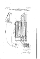
Fig. l 'is a side-view ofthe'first form of constructingthe burner. r I
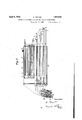
Fig. 2 is a longitudinal section of a devel- V opment of the burner.- t Fig; 13 shows the second form in which the burner-handle is represented in development, 7
while the burner mouth-piece consisting of several parts 1s shown in SGCtlOH; I
According; to the form of Figsf'l and l the liquid fuel is led into a pipe where it distributes itself on four gas-developers 1 1 ,121
inwhich it is gasified, thegasstreaminginto the gas accumulator In the gas-developers 1 1 1 1" exchange- I able cores 0 ,103 e -f are insertedprovided,
latter with a cover of asbestos for the reception of residues resulting from the development of gas.
By the opening of valves 1", q, p, burninggas streams from the gas-accumulator 1 through pipes m, n, 0 and further through pipes f, g, h into the heating-nozzles b, 0, (Z
By the opening of valves 9 h, i the oxygen streams through pipes 15, u, v and further through pipes f, g, h into the heating-nozzles The fusing-oxygen, after opening valve 8, streams through a pipe i into the fusing-nozzle (1.
Through electric radiators w, y the heat in the heating-chamber k which is enveloped by a mantle a is developed for gasifying the liquid fuel. The heating can be regulated.
A safety-valve 2 opens and closes automatically when overpressure is caused through evaporization in the heating-chamber k.
The oxygen-pipes s, 9 h i are supplied out of branch-pipes from an oxygen supplyconduit not shown in drawings, in which a relief-valve is arranged. Into the conduit for supplying liquid fuel to pipe 10 a reliefvalve is also provided.
In the form carried out as per Fig. 3 the burner-head is provided with bores separate from each other and widened at their upper end for reception of the oxygen-supply pipes i, t, u, v and the fuel supply pipes m, n, 0.
The single parts a, b, c, d of the complex burner mouth-piece are screwed on to the actual burner-head 0, so as to form ring-channels in which the oxygen and the gases, so far conducted entirely separate from each other, can mix. On the inside, the single part-s of the burner mouth-piece are provided with trusses B against which the gases and the oxygen beat, thereby causing a whirl and a good mixture. For controlling the heatingvalue of the gas-mixture, the supply currents can be regulated.
1, 1 1 1 are the gas-developers from which the gases stream into the accumulator 1. 0 d 6 f are exchangeable insertioncores provided with asbestos insulation for reception of residues from the development of gas. as, y are electric heat-radiators.
Through opening valves 0, g, p the burning-gas streams out of the accumulator 1 through pipes m, n, 0, immediately into the burner-head. Through opening valves 9 h, 2' the welding-oxygen streams through pipes t, u, '2) separate from pipes m, n, 0 into the burner-head.
Through opening valve 8, the fusing-oxygen streams through a pipe 1' into the fusingnozzle a.
For clearness sake, all pipes m, n, 0, t, u, o and i are shown broken off when leaving the burner-handle a Their connection with theburner-head is indicated by strokes.
A safety-valve 2 opens and closes automatically when overpressure occurs through evaporization in the heating-chamber In.
What I claim as my invention, and desire to secure by Letters Patent, is:
1. A burner for the autogenous cutting and welding under water, comprising a plurality of gasifying chambers, electrical heating devices mounted in said chambers, an accumulating chamber into which the gasifying chambers empty, pipes connecting the accumulating chamber with the burner, and oxygen supplying pipes passing through the accumulating chamber and connected with the burner.
2. A burner for the autogenous cutting and welding under water comprising a plurality of electrically heated gasifying chambers, an accumulating chamber into which the gasifying chambers discharge, a heating nozzle formed with a plurality of annular channels, pipes connecting the accumulating chamber and channels, and oxygen supplying pipes passing through the accumulating chamber and communicating with the channels of the nozzle.
3. A device as claimed in claim 2, wherein trusses are mounted in the annular channels of the heating nozzle near their outlets to limit the fiareback of flame.
4. A burner for the autogenous fusing and welding under water, a plurality of gasifying chambers, electrical heating means in the chambers for gasifying liquid fuel therein, an accumulating chamber, a plurality of heating nozzles, pipes connecting said chamber and heating nozzles, and oxygen conducting pipes connected with said pipes for supplying oxygen thereto. I
In testimony whereof I have signed my name to this specification.
HARRY TUPPER.
Applications Claiming Priority (1)
| Application Number | Priority Date | Filing Date | Title |
|---|---|---|---|
| DE1852946X | 1929-07-30 |
Publications (1)
| Publication Number | Publication Date |
|---|---|
| US1852946A true US1852946A (en) | 1932-04-05 |
Family
ID=7746091
Family Applications (1)
| Application Number | Title | Priority Date | Filing Date |
|---|---|---|---|
| US469594A Expired - Lifetime US1852946A (en) | 1929-07-30 | 1930-07-21 | Burner for autogenous fusing and welding under water |
Country Status (1)
| Country | Link |
|---|---|
| US (1) | US1852946A (en) |
Cited By (1)
| Publication number | Priority date | Publication date | Assignee | Title |
|---|---|---|---|---|
| US2484272A (en) * | 1947-08-05 | 1949-10-11 | Crowe John Marshall | Fluid burner with auxiliary external oxygen supply |
-
1930
- 1930-07-21 US US469594A patent/US1852946A/en not_active Expired - Lifetime
Cited By (1)
| Publication number | Priority date | Publication date | Assignee | Title |
|---|---|---|---|---|
| US2484272A (en) * | 1947-08-05 | 1949-10-11 | Crowe John Marshall | Fluid burner with auxiliary external oxygen supply |
Similar Documents
| Publication | Publication Date | Title |
|---|---|---|
| US1852946A (en) | Burner for autogenous fusing and welding under water | |
| US2157265A (en) | Oil burner | |
| US574719A (en) | Friedrich drumm | |
| US360558A (en) | Liquid hydrocarbons | |
| US1181674A (en) | Gas-heater for furnaces. | |
| US1633175A (en) | Hydrocarbon burner | |
| US1393706A (en) | Oil-stove | |
| US1981766A (en) | Burner for liquid fuel especially for cutting and welding under water | |
| US1049034A (en) | Gas-generator. | |
| US709493A (en) | Atmospheric gas-heating burner. | |
| US948009A (en) | Burner. | |
| US659668A (en) | Hydrocarbon-burner. | |
| US735831A (en) | Hydrocarbon-vapor generator. | |
| US2523096A (en) | Liquid fuel vaporizer | |
| US423347A (en) | Half to charles | |
| US378411A (en) | Assigkoe to himself and asa | |
| US1143057A (en) | Burner for water-heaters. | |
| US677314A (en) | Gasolene-torch attachment for vapor-burning lamps. | |
| US396049A (en) | Oil-burner | |
| US597028A (en) | Rateurs a vaporisation instantane | |
| US665670A (en) | Gasolene-burner. | |
| US380514A (en) | Generating retort and burner attached | |
| US397749A (en) | Hydrocarbon-burner | |
| US850897A (en) | Soldering-iron. | |
| US1131916A (en) | Oil-burner. |