US1852929A - Helicopter toy - Google Patents
Helicopter toy Download PDFInfo
- Publication number
- US1852929A US1852929A US567486A US56748631A US1852929A US 1852929 A US1852929 A US 1852929A US 567486 A US567486 A US 567486A US 56748631 A US56748631 A US 56748631A US 1852929 A US1852929 A US 1852929A
- Authority
- US
- United States
- Prior art keywords
- shaft
- helicopter
- fuselage
- propeller
- axle
- Prior art date
- Legal status (The legal status is an assumption and is not a legal conclusion. Google has not performed a legal analysis and makes no representation as to the accuracy of the status listed.)
- Expired - Lifetime
Links
- 241000239290 Araneae Species 0.000 description 6
- 238000004873 anchoring Methods 0.000 description 4
- 238000010276 construction Methods 0.000 description 1
- 230000000694 effects Effects 0.000 description 1
- 230000000717 retained effect Effects 0.000 description 1
Images
Classifications
-
- A—HUMAN NECESSITIES
- A63—SPORTS; GAMES; AMUSEMENTS
- A63H—TOYS, e.g. TOPS, DOLLS, HOOPS OR BUILDING BLOCKS
- A63H27/00—Toy aircraft; Other flying toys
- A63H27/005—Rockets; Missiles
Definitions
- This invention relates tocertain new and useful improvements in helicopter toys.
- the primary object of the invention is to provide a wheeled to in the form of an aeroof plane comprising a hody portion supported on wheels with an upwardly disposed horizontal helicopter propeller that may be operated by'wind for driving the ground wheels and a forwardly positioned propeller. It is 10 a further object of the invention to provide a helicopter toy of the foregoing character wherein a perpendicular shaft extending through the body portion has gear connections with ground wheels and a forwardly 15 positioned propeller with an elastic cord associated with the shaft for rotating the same to impart movement to the toy.
- a still further objectof the invention isv to provide a helicopter toy embodying an upper horizontal propeller and the usual forward propeller with the operating means therefor constructed in a manner to permit operation of either or both of the propellers without producing forward movement of the toy.
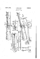
- Figure 1 is a rout elevational View of a a helicopter toy constructed in accordance with the present invention, the upper heli- .copter propeller beingillustrated as disengaged from driving connection with the driving shaft; o
- Figure 2 1s a side elevational View of the toy showing the elastic cord associated with the drive shaft and with the helicopter propellerbeing secured to the drive shaft;
- Figure 3 is a top plan view of the spider frame carrying the blades of the helicopter propeller with one blade illustrated;
- Figures 4 and 5 show two forms of elast1c cord for operating the drive shaft.
- a helicopter aeroplane toy comprising a body portion or fuselage carrying forwardly disposed cllassls arms 11 for the support of an axle 12 upon which ground wheels 13 are mounted, the skid support for the rear end of the fuse- 55.
- lage including an arm 14 journalled in the fuselage and carrying a. ground wheel 15, while the link 16 carried by the ar, .1 14 may bev horizontally shifted and engaged with the fuselage for changing the position of the skid wheel 15 for pur ose of steering the toy.
- a vertical sha t 17 is ournalled to the fuse lage 10 above the axle 12 with the lower end extending below the fuselage and carrying a bevel gear 18 fixed thereto that is in meshing engagement with the bevel gear 19 journalled upon the axle 12.
- the bevel ear 19 being selectively locked or keyed to t e axle 12 by means of thekey 2O pivotally mounted u on'the axle at one endthereof as at 21, 7 the ey being illustrated in its full lines in Figure 1, engaged with the gear 19forlocking the same to the axle while the released position thereof is illustrated b dotted lines.
- a shaft 22 extends longitu inally of the we forward end of the fuselage, projects from the forward end thereof and carries the usual propeller 23, the rear end of the shaft 22 carrying a bevel gear 24-. in meshing engagem7ent with the bevel gear 25 fixed to the shaft so 1 v
- the shaft 17 extends above the fuselage and through the spread wing 26 as illustrated and receives upon its terminal upper end a helicopter propeller.
- the helicopter propeller comprises a central spider frame 27 having an opening 28 therein for rotatable reception upon the upper end of the shaft 17 with radial arms 29 carried by the spider frame and having apertured plate portions 30 at their outer ends to facilitate the support of and attachment to the helicopter blades.
- Each helicopter blade is of V-formation and includes opposed side walls 31 and 32, the wall 32 being of a width substantially twice the width of the wall 31 while curved wind buffer and brace 33 extends between the free edge of the wall '31 and the intermediate portion of the wall 32.
- the spider frame 27 is retained upon the upper en of the shaft 17 m by a securing nut 34 as illustrated in Figures 1 and 2.
- T e shaft 17 for a portion of the len h thereof below the bearing for the spi er frame is threaded as at 17 a and has a nut 35 threaded thereon that is operated by a handle 36, the helicopter propeller being freely journalled upon the upper end of the shaft 17 when the nut 35 is spaced therefrom as illustrated in Figure 1, while the helicopter propeller is locked to the shaft 17 when the nut 35 is engaged with the bearing portion thereof as illustrated in Figure 2,
- the operating means for the shaft 17 includes an elastic cord 37 shown in Figures 2 and 5, having a looped portion 38 at each end thereof, one loop 38 being engaged with a hook on the shaft 17 above the wing 26 and rotected by a cover plate 39, the elastic cord being then directed rearwardly to a point adjacent the rear end of the fuselage as at 40 to be passed through an openin in the fuselage and forwardl directed with the other looped end thereo engaged with a hook 41 upon the under side of the fuselage adjacent the wheel chassis as illustrated in Figure 2.
- Another form of elastic cord 37a is illustrated in Fi re 4 having flattened ends slitted as at 38a Eff attachment to the respective hooks upon the shaft 17 and the under side of the fuselage 10.
- the elastic cord may be laced under tension by rotating the shaft 17 by means of the helicopter propeller with the wheels 13 elevated from the ground and when proper power has been vested in the elastic cord, the aeroplane toy is placed upon the ground with the elastic cord rotating the shaft 17 to operate the forward propeller 2 3 and the helicopter propeller, the shaft 17 driving the axle 12 and ground wheels 13.
- the direction of movement of the helicopter toy may be controlled by the rear skid wheel 15.
- I claim 1 In a toy aeroplane, a fusela e, an axle and ground wheels carried there y a helicopter and forward propeller on the fuselage, power means for operating the propellers and axle, including a shaft extending perpendicularly through the fuselage, an elastic cord anchored at one end to the fuselage and at its other end to the shaft to be wound thereon, the helicpoter being journalled on the up per end of the shaft, and a nut threaded on the shaft to be moved into binding engagement with the hub of the helico Jter for anchoring the helicpoter to the sha t.
- a toy aeroplane a fusela e, an axle and ground wheels carried there y, a helicopter and forward propeller on the fuselage, operating means for the propellers selectively en aged with the axle, including a shaft exten ing prependicularly through the fuselage, an elastic cord anchored at one end to the fuselage and at its other end to the shaft to be wound thereon, the helicopter being journalled on the upper end of the shaft, and a nut threaded on the shaft to be moved into the binding engagement with the hub of the helicopter for anchoring the helicopter to the shaft.
- a fuselage In a toy aeroplane, a fuselage, an axle and ground wheels carried thereby, a helicopter and forward propeller on the fuselage, power means for operating the propellers and axle, including a shaft extending perpendicularly through the fuselage, an elastic cord anchored at one end to the fuselage and at its other end to the shaft to be wound thereon, the helicopter being journalled on the upper end of the shaft, means for anchoring the helicopter to the shaft, a bevel gear fixed to the lower end of the shaft, a
- a toy aeroplane a fusela e, an axle and ground wheels carried there y, a helicopter and forward propeller on the fuselage, operating means for the propellers selectively engaged with the axle, including a shaft extending perpendicularly through the fuselage, an elastic cord anchored at one end to the fuselage and at its other end to the shaft to be wound thereon, the helicopter being 3ournalled on the upper end of the shaft, means for anchoring the helicopter to the shaft, a bevel gear fixed to the lower end of the shaft, a bevel gear journalled on the axle 1n meshttherewith, and means for locking the last named gear to the axle.
Landscapes
- Toys (AREA)
Description
April 5, 1932. J. HCIJJNOWSKI I gwuentoo 6 M? )WSNNS SQ. g y
HELICOPTER TOY Filed Oct. 7, 1931 Patented Apr. 5, 1932 JAKQB HOJ'NOWSKI, OF NEKUOSA, WISCONSIN HELICOPTER TOY Application filed October 1, 1931. Serial No. 567,486.
This inventionrelates tocertain new and useful improvements in helicopter toys.
The primary object of the invention is to provide a wheeled to in the form of an aeroof plane comprising a hody portion supported on wheels with an upwardly disposed horizontal helicopter propeller that may be operated by'wind for driving the ground wheels and a forwardly positioned propeller. It is 10 a further object of the invention to provide a helicopter toy of the foregoing character wherein a perpendicular shaft extending through the body portion has gear connections with ground wheels and a forwardly 15 positioned propeller with an elastic cord associated with the shaft for rotating the same to impart movement to the toy.
A still further objectof the invention isv to provide a helicopter toy embodying an upper horizontal propeller and the usual forward propeller with the operating means therefor constructed in a manner to permit operation of either or both of the propellers without producing forward movement of the toy.-
With the above and other objects in view that will become apparent as the nature of the invention is better understood, the same consists in the novel form, combination and arran ement of parts hereinafter more fully descri ed, shown in the accompanying drawings and claimed.
In the drawin s:-
' Figure 1 is a rout elevational View of a a helicopter toy constructed in accordance with the present invention, the upper heli- .copter propeller beingillustrated as disengaged from driving connection with the driving shaft; o
Figure 2 1s a side elevational View of the toy showing the elastic cord associated with the drive shaft and with the helicopter propellerbeing secured to the drive shaft;
Figure 3 is a top plan view of the spider frame carrying the blades of the helicopter propeller with one blade illustrated; and
Figures 4 and 5 show two forms of elast1c cord for operating the drive shaft.
Referring more in detail to the accompanying drawings, there is illustrated a helicopter aeroplane toy comprising a body portion or fuselage carrying forwardly disposed cllassls arms 11 for the support of an axle 12 upon which ground wheels 13 are mounted, the skid support for the rear end of the fuse- 55. lage including an arm 14 journalled in the fuselage and carrying a. ground wheel 15, while the link 16 carried by the ar, .1 14 may bev horizontally shifted and engaged with the fuselage for changing the position of the skid wheel 15 for pur ose of steering the toy.
A vertical sha t 17 is ournalled to the fuse lage 10 above the axle 12 with the lower end extending below the fuselage and carrying a bevel gear 18 fixed thereto that is in meshing engagement with the bevel gear 19 journalled upon the axle 12. The bevel ear 19 being selectively locked or keyed to t e axle 12 by means of thekey 2O pivotally mounted u on'the axle at one endthereof as at 21, 7 the ey being illustrated in its full lines in Figure 1, engaged with the gear 19forlocking the same to the axle while the released position thereof is illustrated b dotted lines.
A shaft 22 extends longitu inally of the we forward end of the fuselage, projects from the forward end thereof and carries the usual propeller 23, the rear end of the shaft 22 carrying a bevel gear 24-. in meshing engagem7ent with the bevel gear 25 fixed to the shaft so 1 v The shaft 17 extends above the fuselage and through the spread wing 26 as illustrated and receives upon its terminal upper end a helicopter propeller. The helicopter propeller comprises a central spider frame 27 having an opening 28 therein for rotatable reception upon the upper end of the shaft 17 with radial arms 29 carried by the spider frame and having apertured plate portions 30 at their outer ends to facilitate the support of and attachment to the helicopter blades. Each helicopter blade is of V-formation and includes opposed side walls 31 and 32, the wall 32 being of a width substantially twice the width of the wall 31 while curved wind buffer and brace 33 extends between the free edge of the wall '31 and the intermediate portion of the wall 32. The spider frame 27 is retained upon the upper en of the shaft 17 m by a securing nut 34 as illustrated in Figures 1 and 2. T e shaft 17 for a portion of the len h thereof below the bearing for the spi er frame is threaded as at 17 a and has a nut 35 threaded thereon that is operated by a handle 36, the helicopter propeller being freely journalled upon the upper end of the shaft 17 when the nut 35 is spaced therefrom as illustrated in Figure 1, while the helicopter propeller is locked to the shaft 17 when the nut 35 is engaged with the bearing portion thereof as illustrated in Figure 2,
The operating means for the shaft 17 includes an elastic cord 37 shown in Figures 2 and 5, having a looped portion 38 at each end thereof, one loop 38 being engaged with a hook on the shaft 17 above the wing 26 and rotected by a cover plate 39, the elastic cord being then directed rearwardly to a point adjacent the rear end of the fuselage as at 40 to be passed through an openin in the fuselage and forwardl directed with the other looped end thereo engaged with a hook 41 upon the under side of the fuselage adjacent the wheel chassis as illustrated in Figure 2. Another form of elastic cord 37a is illustrated in Fi re 4 having flattened ends slitted as at 38a Eff attachment to the respective hooks upon the shaft 17 and the under side of the fuselage 10. a
From the above detailed description of the invention, it is believed that the construction and operation thereof will at once he apparcut, it being noted that when the helicopter ropeller is locked to the shaft 1'7 and the vel gear 19 is locked to the shaft 12, the elastic cord may be laced under tension by rotating the shaft 17 by means of the helicopter propeller with the wheels 13 elevated from the ground and when proper power has been vested in the elastic cord, the aeroplane toy is placed upon the ground with the elastic cord rotating the shaft 17 to operate the forward propeller 2 3 and the helicopter propeller, the shaft 17 driving the axle 12 and ground wheels 13. The direction of movement of the helicopter toy may be controlled by the rear skid wheel 15. With the helicopter propeller again keyed to the shaft 17, it is possible to effect operation of both the helicopter propeller and the forwardly positioned propeller 23 by use of the elastic cord 37 without forwardly propelling the toy by disengaging the key 20 upon the axle 12 from the bevel gear 19, the result being that the gear 19 freely rotates upon the axle 12 without effecting movement of the ground wheels 13.
While there are herein shown and described the preferred embodiments of the invention, it is nevertheless to be understood that minor changes may be made therein without departing from the spirit and scope of the invention as claimed.
I claim 1. In a toy aeroplane, a fusela e, an axle and ground wheels carried there y a helicopter and forward propeller on the fuselage, power means for operating the propellers and axle, including a shaft extending perpendicularly through the fuselage, an elastic cord anchored at one end to the fuselage and at its other end to the shaft to be wound thereon, the helicpoter being journalled on the up per end of the shaft, and a nut threaded on the shaft to be moved into binding engagement with the hub of the helico Jter for anchoring the helicpoter to the sha t.
2. In a toy aeroplane, a fusela e, an axle and ground wheels carried there y, a helicopter and forward propeller on the fuselage, operating means for the propellers selectively en aged with the axle, including a shaft exten ing prependicularly through the fuselage, an elastic cord anchored at one end to the fuselage and at its other end to the shaft to be wound thereon, the helicopter being journalled on the upper end of the shaft, and a nut threaded on the shaft to be moved into the binding engagement with the hub of the helicopter for anchoring the helicopter to the shaft.
3. In a toy aeroplane, a fuselage, an axle and ground wheels carried thereby, a helicopter and forward propeller on the fuselage, power means for operating the propellers and axle, including a shaft extending perpendicularly through the fuselage, an elastic cord anchored at one end to the fuselage and at its other end to the shaft to be wound thereon, the helicopter being journalled on the upper end of the shaft, means for anchoring the helicopter to the shaft, a bevel gear fixed to the lower end of the shaft, a
evel gear journalled on the axle in mesh therewlth, and means for locking the last named gear to the axle.
4. In a toy aeroplane, a fusela e, an axle and ground wheels carried there y, a helicopter and forward propeller on the fuselage, operating means for the propellers selectively engaged with the axle, including a shaft extending perpendicularly through the fuselage, an elastic cord anchored at one end to the fuselage and at its other end to the shaft to be wound thereon, the helicopter being 3ournalled on the upper end of the shaft, means for anchoring the helicopter to the shaft, a bevel gear fixed to the lower end of the shaft, a bevel gear journalled on the axle 1n meshttherewith, and means for locking the last named gear to the axle.
5. In a toy aeroplane, a and ground wheels carried thereby, a helicopter and forward propeller on the fuselage, and power means for operating the pro ellers and axle, the helicopter propeller inc uding a central spider frame, a propeller blade carried by each spider arm and of spaced
Priority Applications (1)
| Application Number | Priority Date | Filing Date | Title |
|---|---|---|---|
| US567486A US1852929A (en) | 1931-10-07 | 1931-10-07 | Helicopter toy |
Applications Claiming Priority (1)
| Application Number | Priority Date | Filing Date | Title |
|---|---|---|---|
| US567486A US1852929A (en) | 1931-10-07 | 1931-10-07 | Helicopter toy |
Publications (1)
| Publication Number | Publication Date |
|---|---|
| US1852929A true US1852929A (en) | 1932-04-05 |
Family
ID=24267360
Family Applications (1)
| Application Number | Title | Priority Date | Filing Date |
|---|---|---|---|
| US567486A Expired - Lifetime US1852929A (en) | 1931-10-07 | 1931-10-07 | Helicopter toy |
Country Status (1)
| Country | Link |
|---|---|
| US (1) | US1852929A (en) |
Cited By (5)
| Publication number | Priority date | Publication date | Assignee | Title |
|---|---|---|---|---|
| US2469144A (en) * | 1946-11-13 | 1949-05-03 | Ideal Novelty & Toy Co | Toy airplane |
| US2518007A (en) * | 1945-06-01 | 1950-08-08 | Gerard P Herrick | Aircraft operable either as fixed or rotary lifting surface type |
| US2732656A (en) * | 1956-01-31 | Toy helicopter | ||
| US2755596A (en) * | 1953-04-14 | 1956-07-24 | Weil Hans Hermann | Mechanical system for a flying toy |
| US3229414A (en) * | 1962-12-15 | 1966-01-18 | Frank T Johmann | Propeller-driven toy |
-
1931
- 1931-10-07 US US567486A patent/US1852929A/en not_active Expired - Lifetime
Cited By (5)
| Publication number | Priority date | Publication date | Assignee | Title |
|---|---|---|---|---|
| US2732656A (en) * | 1956-01-31 | Toy helicopter | ||
| US2518007A (en) * | 1945-06-01 | 1950-08-08 | Gerard P Herrick | Aircraft operable either as fixed or rotary lifting surface type |
| US2469144A (en) * | 1946-11-13 | 1949-05-03 | Ideal Novelty & Toy Co | Toy airplane |
| US2755596A (en) * | 1953-04-14 | 1956-07-24 | Weil Hans Hermann | Mechanical system for a flying toy |
| US3229414A (en) * | 1962-12-15 | 1966-01-18 | Frank T Johmann | Propeller-driven toy |
Similar Documents
| Publication | Publication Date | Title |
|---|---|---|
| US3035789A (en) | Convertiplane | |
| US1861336A (en) | Airplane | |
| US1852929A (en) | Helicopter toy | |
| US2442846A (en) | Wind-driven helicopter kite | |
| CN201052838Y (en) | Manpower aircraft | |
| US2076090A (en) | Propeller | |
| US2226978A (en) | System including rotary blades | |
| US1819794A (en) | Aeroplane | |
| US2382347A (en) | Toy helicopter | |
| US2110443A (en) | Empennage for rotary winged aircraft | |
| US3220670A (en) | Helicopter | |
| US1832254A (en) | Airplane | |
| US2405244A (en) | Rotary wing aircraft | |
| US2308916A (en) | Vertically rising flying device | |
| US1875891A (en) | Gyroscopic airplane | |
| US2420823A (en) | Helicopter | |
| US2242628A (en) | Airplane launching device | |
| US2400704A (en) | Toy helicopter | |
| US1867759A (en) | Aircraft | |
| US1789254A (en) | Flying machine | |
| US3205960A (en) | Ground effect machine | |
| US1498412A (en) | Helico-plane | |
| US3131888A (en) | Amphibious helicopter with detachable hull | |
| US1738611A (en) | Aeroplane | |
| US1403595A (en) | Aeroplane toy |