US1852925A - Collapsible radio antenna - Google Patents
Collapsible radio antenna Download PDFInfo
- Publication number
- US1852925A US1852925A US546143A US54614331A US1852925A US 1852925 A US1852925 A US 1852925A US 546143 A US546143 A US 546143A US 54614331 A US54614331 A US 54614331A US 1852925 A US1852925 A US 1852925A
- Authority
- US
- United States
- Prior art keywords
- mast
- antenna
- radial arms
- cap member
- carried
- Prior art date
- Legal status (The legal status is an assumption and is not a legal conclusion. Google has not performed a legal analysis and makes no representation as to the accuracy of the status listed.)
- Expired - Lifetime
Links
- 239000004020 conductor Substances 0.000 description 9
- 239000011810 insulating material Substances 0.000 description 6
- 239000012212 insulator Substances 0.000 description 4
- 238000010276 construction Methods 0.000 description 3
- 210000003128 head Anatomy 0.000 description 2
- 230000005540 biological transmission Effects 0.000 description 1
- 210000005069 ears Anatomy 0.000 description 1
- 239000010985 leather Substances 0.000 description 1
- 239000000463 material Substances 0.000 description 1
- 239000002184 metal Substances 0.000 description 1
- 238000000034 method Methods 0.000 description 1
- 239000002023 wood Substances 0.000 description 1
Images

Classifications
-
- H—ELECTRICITY
- H01—ELECTRIC ELEMENTS
- H01Q—ANTENNAS, i.e. RADIO AERIALS
- H01Q7/00—Loop antennas with a substantially uniform current distribution around the loop and having a directional radiation pattern in a plane perpendicular to the plane of the loop
- H01Q7/02—Collapsible antennas; Retractable antennas
Definitions
- My invention relates broadly to antennae for receiving and transmitting radio waves and more particularly to a collapsible type of antenna which may be conveniently transported from place to place.
- Anobject of my invention is to provide an antenna which will receive or transmit equally well in all directions and may be quickly erected upon any building.
- a further object of my invention is to provide a collapsible antenna which may be easily mounted upon roofs of various types and which may be manufactured at a reason able cost.
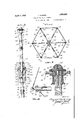
- Figure 1 shows a side view of the antenna erected and in position
- Figure 2 shows a view in horizontal cross section on the line 22 of Figure 1;
- Figure 3 shows a view in vertical cross section of the upper part of the mast and cap member
- Figure 4 shows a view in section of the outer portion of the radial arm and insulator Figure 5 shows a side view of the antenna in collapsed position;
- Figure 6 shows a detail of the rack members for locking the radial arms in position, taken on the line 6-6 of Figure 1;
- Figure 7 shows a detail of the ring member carried by the mast for supporting the radial arms.
- antenna element outside of any building for the purpose of receiving and radiating radio waves. If such antennae are mounted inside of the building, appreciable energy losses will necessarily occur in the surrounding walls and the reception and transmission will be less efficient.
- the type of antenna ordinarily employed has marked directional characteristics and will receive and trans- 1931. Serial N0. 546,143.
- FIG. 1 shows a general side view of my antenna structure.
- the numeral 1 denotes the mast which may be of wood or metal or other suitable composition. Attached to the base of the mast by rivets or bolts 2 are hinges 3 which are fastened by screws 4: to the roof 5. The hinges permit the adjustment of the mast to a vertical position on any type of roof, whether flat or gable.
- the numeral 6 denotes a cap member carried at the top of the mast and provided with a flange 7 hav ing a flared edge 8 to facilitate shedding of rain.
- the cap member 6 is provided with parallel flanges 9 and 10 which are adapted to receive a metallic ring element 12.
- the ring element 12 is multiply apertured adjacent its periphery to receive the radiating and receiving antenna wire elements 18.
- the top of the cap member 6 is provided with a dome 14 which is suitably curved to shed rain.
- a ring member 23 is mounted to slide along the mast. 1.
- a plurality of radial arms 22 are pivotally mounted on the ring 23 as shown in detail in Figure 2.
- Radial arms 22 may be provided at their outer ends with in sulators 21 which are circumferentially ribbed at 20 to shed rain. Eyes 19 are carried on the outer ends of insulators 21 to receive the lower ends of radiating and receiving antenna wires 18.
- the radial arms 22 are pivotally mounted on ears 24.
- the ring member 23 is provided with a set screw 25 which is adapted to engage recesses in rack members 31 and 32 to retain the ring member 23 in fixed position.
- Rack members 31 and 32 are mounted below the circumferential surface of the mast 1 so that the ring member 23 may slide easily over the rack members when the set screw 25 is released.
- a collar 27 is fixed to the mast 1 above the rack member 31 and pivotally supports braces 28 and 29.
- the braces 28 are pivotally attached to radial arms 22 at approximately the midpoints thereof.
- the braces 28 and 29 are slotted and adapted to slide over each other and are provided with wing bolts and nuts 30 to lock the braces 28 and 29 in position.
- a collecting conductor 33 is attached to the lower ends of the antenna wires 18 at the point at which they are attached to the outer ends of the radial arms 22.
- Lead-in wire 34 is attached to the conductor 33.
- a lightning arrester 35 is connected between the lead-in conductor 34 and ground 36.
- a series condenser 37 may be connected between lead-in conductor 34 and the antenna terminal of the receiving or transmitting set 38.
- Radial arms 22 may be braced from below by rods 39 and 41 pro vided with turn-buckles 4Q.
- the radial arms 22 are provided with eyes 43 and the mast 1 is provided with eyes 42 for receiving rods 39 and 41.
- the mast may be guyed to the roof or other surface by means of guy ropes 44 attached to eyes 45 carried on the mast 1 and attached to eyes 46 on the roof or other surface.
- a strap 47 of leather or other suitable material may be provided on the mast 1. to hold the antenna wires 18 in compact position when the antenna is collapsed.
- Figure 3 is shown a detail form of construction of the cap member 6 which I have found particularly desirable.
- the head of a retaining bolt 15 is molded into the cap member 6 which is preferably composed of molded electrical insulating material.
- the part of the pin member 15 projecting outside of the cap member 6 is provided with coarse screw threads.
- the top portion of the mast 1 is recessed to receive the outwardly extending portion of the pin 15 and is filled with a cementitious aggregate 16 to hold the pin 15 in place.
- the cap member 6 is provided with a skirt or flange 8 to more easily shed rain.
- the annular flange member 10 may be made separate from the cap member 6 so that it may be easily detached and may be screwthreaded as shown at 11.
- turnbuckles 40 When it is desired to dismount the antenna, turnbuckles 40 are released and radial arms 22 may then be pushed upward and the en tire antenna structure collapsed. Antenna wires 18 may then be held tightly in compact position by means of strap 47.
- the hinged members 3 may be quickly removed by removing the screws 4 and the entire antenna structure may be dismounted or erected in a time not exceeding fifteen minutes.
- a mast adjustable mounting hinges carried by the base of said mast, a ring member slidable along said mast, a plurality of radial arms pivotally mounted on said ring member, a plurality of braces attached to said mast an respectively to individual ones of said radial arms, each of said braces consisting of a pair of slotted members slidably adjustable over each other, a cap member carried on the top of said mast and consisting of molded electrical insulating material, said cap member being annularly recessed, an annular metallic collector plate carried in the annular recess of said cap member, said collector plate being circumferentially multiply apertured, a plurality of Wave collecting and radiating elements respectively supported between apertures in said collector plate and the ends of said radial arms, a conductor connecting the ends of said collecting and radiating elements together and attached thereto at the outer ends of said radial arms and means for retaining said ring member in a fixed position on said mast.
- a mast In a collapsible antenna, a mast, adjustable mounting hinges carried by the base of said mast, a ring member slidable along said mast, a plurality of radial arms pivotally mounted on said ring member, a plurality of braces attached to said mast and respectively to individual ones of said radial arms, each of said braces consisting of a pair of slotted members slidably adjustable over each other, a plurality of peripherally ribbed insulators carried respectively on the outer ends of said radial arms, a cap member carried on the top of said mast and consisting of molded electrical insulating material, said cap member being annularly recessed, an annular metallic collector plate carried in the annular recess of said cap member, said collector plate being circumferentially multiply apertured, a plurality of wave collecting and radiating elements respectively supported between apertures in said collector plate and said insulators carried on said radial arms, a conductor connecting the ends of said collecting and radiating elements together and attached thereto at the outer ends of
- a mast In a collapsible antenna, a mast, adjustable mounting hinges carried by the base of said mast, a ring member slidable along said mast, a plurality of radial arms pivotally mounted on said ring member, a plurality of braces attached to said mast and respectively to individual ones of said radial arms, each of said braces consisting of a pair of slotted members slidably adjustable over each other, a cap member carried on the top of said mast and consisting of molded electrical insulating material, said cap member being annularly recessed, an annular metallic collector plate carried in the annular recess of said cap member, said collector plate being circumferentially multiply apertured, said cap member being provided with an annular separable member removably attached to said cap member and adapted to retain said collector plate, said mast being recessed at its upper end, a coarsely threaded pin having its head embedded in said cap member and extending downwardly into the recess in the top of said mast, the recess in the top of said
- a mast adjustable mounting hinges carried by the base of said mast, a ring member slidable along said mast, a plurality of radial arms pivotally mounted on said ring member, a plurality of braces attached to said mast and respectively to individual ones of said radial arms, each of said braces consisting of a pair of slotted members slidably adjustable over each other, a cap member carried on the top of said mast and consisting of molded electrical insulating material, said cap member being annularly recessed, an annular metallic collector plate carried in the annular recess of said cap member, said collector plate being circumferentially multiply apertured, a plurality of wave collecting and radiating elements respectively supported between apertures in said collector plate and the ends of said radial arms, a conductor connecting the ends of said collecting and radiating elements together and attached thereto at the outer ends of said radial arms, racks disposed below the surface of said mast and an adj ustable locking screw carried by said ring member and adapted
- a mast adjustable mounting hinges carried by the base of said mast, a ring member slidable along said mast, a plurality of radial arms pivotally mounted on said ring member, a plurality of braces attached to said mast and respective ly to individual ones of said radial arms, each of said braces consisting of a pair of slotted members slidably adjustable over each other, a cap member carried on the top of said mast and consisting of molded electrical insulating material, said cap member being annularly recessed, an annular metallic collector plate carried in the annular recess of said cap member, said collector plate being circumferentially multiply apertured, a plurality of wave collecting and radiating elements respectively supported between apertures in said collector plate and the ends of said radial arms, a conductor connecting the ends of said collecting and radiating elements together and attached thereto at the outer ends of said radial arms, means for retaining said ring member in a fixed position on said mast, and a retaining strap carried
Landscapes
- Support Of Aerials (AREA)
Description
April 5, j GOMERY COLLAPSIBLE RADIO ANTENNA Filed June 22, 1931 2 Sheets-Sheet INVENTOR. c706 e al fi o far ATTORNEYS.
Q QE EM N N W 2 a 4 .IV Wu w W 4 J m\\\\ 6 i 4 April 5, 1932. J. GOMERY COLLAPSIB-LE RADIC ANTENNA Filed June 22, 1931 2 Sheets-Sheet 2 INVENTOR,
Iii-"a cjas e vfi Qajgar By I r (1 TORNEYS.
Patented Apr. 5, 1932 PATENT OFFICE JOSEPH GOMERY, OF LOS AN GELES, CALIFORNIA COLLAPSIBLE RADIO ANTENNA Application filed June 22,
My invention relates broadly to antennae for receiving and transmitting radio waves and more particularly to a collapsible type of antenna which may be conveniently transported from place to place.
Anobject of my invention is to provide an antenna which will receive or transmit equally well in all directions and may be quickly erected upon any building.
A further object of my invention is to provide a collapsible antenna which may be easily mounted upon roofs of various types and which may be manufactured at a reason able cost.
With these and numerous objects in View, my invention consists in the novel features of construction, combination and arrangement of parts which will be hereinafter referred to and more particularly pointed out in the specification and claims.
y invention will be understood from the following specification and from the attached drawings wherein Figure 1 shows a side view of the antenna erected and in position;
Figure 2 shows a view in horizontal cross section on the line 22 of Figure 1;
Figure 3 shows a view in vertical cross section of the upper part of the mast and cap member;
Figure 4: shows a view in section of the outer portion of the radial arm and insulator Figure 5 shows a side view of the antenna in collapsed position;
Figure 6 shows a detail of the rack members for locking the radial arms in position, taken on the line 6-6 of Figure 1; and
Figure 7 shows a detail of the ring member carried by the mast for supporting the radial arms.
In the use of radio receiving and transmitting equipment, it is desirable to employ an antenna element outside of any building for the purpose of receiving and radiating radio waves. If such antennae are mounted inside of the building, appreciable energy losses will necessarily occur in the surrounding walls and the reception and transmission will be less efficient. The type of antenna ordinarily employed has marked directional characteristics and will receive and trans- 1931. Serial N0. 546,143.
ally in use at the present time, a considerable amount of time and effort must be expended 4 each time that the antenna is moved because the antenna structures in general use are long and require types of mounting which are difiicult to move. I provide a type of antenna which may be easily dismounted and erected and which will receive and transmit radio waves with high efficiency from and t0 stations located in all directions.
Figure 1 shows a general side view of my antenna structure. The numeral 1 denotes the mast which may be of wood or metal or other suitable composition. Attached to the base of the mast by rivets or bolts 2 are hinges 3 which are fastened by screws 4: to the roof 5. The hinges permit the adjustment of the mast to a vertical position on any type of roof, whether flat or gable. The numeral 6 denotes a cap member carried at the top of the mast and provided with a flange 7 hav ing a flared edge 8 to facilitate shedding of rain. The cap member 6 is provided with parallel flanges 9 and 10 which are adapted to receive a metallic ring element 12. The ring element 12 is multiply apertured adjacent its periphery to receive the radiating and receiving antenna wire elements 18. The top of the cap member 6 is provided with a dome 14 which is suitably curved to shed rain. A ring member 23 is mounted to slide along the mast. 1. A plurality of radial arms 22 are pivotally mounted on the ring 23 as shown in detail in Figure 2. Radial arms 22 may be provided at their outer ends with in sulators 21 which are circumferentially ribbed at 20 to shed rain. Eyes 19 are carried on the outer ends of insulators 21 to receive the lower ends of radiating and receiving antenna wires 18. The radial arms 22 are pivotally mounted on ears 24. The ring member 23 is provided with a set screw 25 which is adapted to engage recesses in rack members 31 and 32 to retain the ring member 23 in fixed position. Rack members 31 and 32 are mounted below the circumferential surface of the mast 1 so that the ring member 23 may slide easily over the rack members when the set screw 25 is released.
A collar 27 is fixed to the mast 1 above the rack member 31 and pivotally supports braces 28 and 29. The braces 28 are pivotally attached to radial arms 22 at approximately the midpoints thereof. The braces 28 and 29 are slotted and adapted to slide over each other and are provided with wing bolts and nuts 30 to lock the braces 28 and 29 in position. By locking the ring member 23 to different positions on the rack member 31, the desired degree of tension may be imparted to antenna wires 18. lVhen it is desired to dismount the antenna, the set screw 25 is released and the ring member 23 is moved to the position corresponding to rack 32 and is there locked in position. A collecting conductor 33 is attached to the lower ends of the antenna wires 18 at the point at which they are attached to the outer ends of the radial arms 22. Lead-in wire 34 is attached to the conductor 33. A lightning arrester 35 is connected between the lead-in conductor 34 and ground 36. A series condenser 37 may be connected between lead-in conductor 34 and the antenna terminal of the receiving or transmitting set 38. Radial arms 22 may be braced from below by rods 39 and 41 pro vided with turn-buckles 4Q. The radial arms 22 are provided with eyes 43 and the mast 1 is provided with eyes 42 for receiving rods 39 and 41. The mast may be guyed to the roof or other surface by means of guy ropes 44 attached to eyes 45 carried on the mast 1 and attached to eyes 46 on the roof or other surface. A strap 47 of leather or other suitable material may be provided on the mast 1. to hold the antenna wires 18 in compact position when the antenna is collapsed. In Figure 3 is shown a detail form of construction of the cap member 6 which I have found particularly desirable. The head of a retaining bolt 15 is molded into the cap member 6 which is preferably composed of molded electrical insulating material. The part of the pin member 15 projecting outside of the cap member 6 is provided with coarse screw threads. The top portion of the mast 1 is recessed to receive the outwardly extending portion of the pin 15 and is filled with a cementitious aggregate 16 to hold the pin 15 in place. The cap member 6 is provided with a skirt or flange 8 to more easily shed rain. The annular flange member 10 may be made separate from the cap member 6 so that it may be easily detached and may be screwthreaded as shown at 11.
When it is desired to dismount the antenna, turnbuckles 40 are released and radial arms 22 may then be pushed upward and the en tire antenna structure collapsed. Antenna wires 18 may then be held tightly in compact position by means of strap 47. The hinged members 3 may be quickly removed by removing the screws 4 and the entire antenna structure may be dismounted or erected in a time not exceeding fifteen minutes.
It will be evident that I have provided a form of antenna structure which is very efficient for receiving and transmitting radio waves and which may be quickly dismounted and erected and may be manufactured in quantities at low cost.
From the foregoing description of my in vention, the method of constructing same an its application to use will be readily understood and it will be seen that I have provided a simple, comparatively inexpensive and most efficient means for carrying out the numerous objects of the invention.
While I have particularly described the elements best adapted to perform the functions set forth, it is obvious that various changes in form, proportion and in the minor details of construction may be resorted to without departing from the spirit or sacrificing any of the principles of the invention.
Having thus described the invention, what I claim is:
1. In a collapsible antenna, a mast, adjustable mounting hinges carried by the base of said mast, a ring member slidable along said mast, a plurality of radial arms pivotally mounted on said ring member, a plurality of braces attached to said mast an respectively to individual ones of said radial arms, each of said braces consisting of a pair of slotted members slidably adjustable over each other, a cap member carried on the top of said mast and consisting of molded electrical insulating material, said cap member being annularly recessed, an annular metallic collector plate carried in the annular recess of said cap member, said collector plate being circumferentially multiply apertured, a plurality of Wave collecting and radiating elements respectively supported between apertures in said collector plate and the ends of said radial arms, a conductor connecting the ends of said collecting and radiating elements together and attached thereto at the outer ends of said radial arms and means for retaining said ring member in a fixed position on said mast.
In a collapsible antenna, a mast, adjustable mounting hinges carried by the base of said mast, a ring member slidable along said mast, a plurality of radial arms pivotally mounted on said ring member, a plurality of braces attached to said mast and respectively to individual ones of said radial arms, each of said braces consisting of a pair of slotted members slidably adjustable over each other, a plurality of peripherally ribbed insulators carried respectively on the outer ends of said radial arms, a cap member carried on the top of said mast and consisting of molded electrical insulating material, said cap member being annularly recessed, an annular metallic collector plate carried in the annular recess of said cap member, said collector plate being circumferentially multiply apertured, a plurality of wave collecting and radiating elements respectively supported between apertures in said collector plate and said insulators carried on said radial arms, a conductor connecting the ends of said collecting and radiating elements together and attached thereto at the outer ends of said radial arms and means for retaining said ring member in a fixed position on said mast.
In a collapsible antenna, a mast, adjustable mounting hinges carried by the base of said mast, a ring member slidable along said mast, a plurality of radial arms pivotally mounted on said ring member, a plurality of braces attached to said mast and respectively to individual ones of said radial arms, each of said braces consisting of a pair of slotted members slidably adjustable over each other, a cap member carried on the top of said mast and consisting of molded electrical insulating material, said cap member being annularly recessed, an annular metallic collector plate carried in the annular recess of said cap member, said collector plate being circumferentially multiply apertured, said cap member being provided with an annular separable member removably attached to said cap member and adapted to retain said collector plate, said mast being recessed at its upper end, a coarsely threaded pin having its head embedded in said cap member and extending downwardly into the recess in the top of said mast, the recess in the top of said mast being filled with cementitious aggregate, a plurality of wave collecting and radiating elements respectively supported between apertures in said collector plate and the ends of said radial arms, a conductor con necting the ends of said collecting and radiating elements together and attached thereto at the outer ends of said radial arms and means for retaining said ring member in a fixed position on said mast.
4. In a collapsible antenna, a mast, adjustable mounting hinges carried by the base of said mast, a ring member slidable along said mast, a plurality of radial arms pivotally mounted on said ring member, a plurality of braces attached to said mast and respectively to individual ones of said radial arms, each of said braces consisting of a pair of slotted members slidably adjustable over each other, a cap member carried on the top of said mast and consisting of molded electrical insulating material, said cap member being annularly recessed, an annular metallic collector plate carried in the annular recess of said cap member, said collector plate being circumferentially multiply apertured, a plurality of wave collecting and radiating elements respectively supported between apertures in said collector plate and the ends of said radial arms, a conductor connecting the ends of said collecting and radiating elements together and attached thereto at the outer ends of said radial arms, racks disposed below the surface of said mast and an adj ustable locking screw carried by said ring member and adapted to engage the recesses in said racks to retain said ring member selectively in a desired position.
5. In a collapsible antenna, a mast, adjustable mounting hinges carried by the base of said mast, a ring member slidable along said mast, a plurality of radial arms pivotally mounted on said ring member, a plurality of braces attached to said mast and respective ly to individual ones of said radial arms, each of said braces consisting of a pair of slotted members slidably adjustable over each other, a cap member carried on the top of said mast and consisting of molded electrical insulating material, said cap member being annularly recessed, an annular metallic collector plate carried in the annular recess of said cap member, said collector plate being circumferentially multiply apertured, a plurality of wave collecting and radiating elements respectively supported between apertures in said collector plate and the ends of said radial arms, a conductor connecting the ends of said collecting and radiating elements together and attached thereto at the outer ends of said radial arms, means for retaining said ring member in a fixed position on said mast, and a retaining strap carried on said mast intermediate said cap member and said braces for retaining said wave collecting and radiating elements compactly in collapsed position.
In testimony whereof, I allix my signature.
JOSEPH GOMERY.
Priority Applications (1)
| Application Number | Priority Date | Filing Date | Title |
|---|---|---|---|
| US546143A US1852925A (en) | 1931-06-22 | 1931-06-22 | Collapsible radio antenna |
Applications Claiming Priority (1)
| Application Number | Priority Date | Filing Date | Title |
|---|---|---|---|
| US546143A US1852925A (en) | 1931-06-22 | 1931-06-22 | Collapsible radio antenna |
Publications (1)
| Publication Number | Publication Date |
|---|---|
| US1852925A true US1852925A (en) | 1932-04-05 |
Family
ID=24179060
Family Applications (1)
| Application Number | Title | Priority Date | Filing Date |
|---|---|---|---|
| US546143A Expired - Lifetime US1852925A (en) | 1931-06-22 | 1931-06-22 | Collapsible radio antenna |
Country Status (1)
| Country | Link |
|---|---|
| US (1) | US1852925A (en) |
Cited By (10)
| Publication number | Priority date | Publication date | Assignee | Title |
|---|---|---|---|---|
| US2901201A (en) * | 1956-02-20 | 1959-08-25 | Northrop Corp | Material handling fixture |
| US3166115A (en) * | 1960-05-14 | 1965-01-19 | Riedel Herbert | Collapsible stand for a flexible projection screen |
| US4249185A (en) * | 1979-04-16 | 1981-02-03 | Cesari Robert J De | Portable, collapsible cubical quad antenna |
| US5052645A (en) * | 1990-03-28 | 1991-10-01 | Hixon Timothy R | Global positioning pole |
| US5608416A (en) * | 1993-04-21 | 1997-03-04 | The Johns Hopkins University | Portable rapidly erectable discone antenna |
| US6018325A (en) * | 1997-10-14 | 2000-01-25 | At&T Corp | Monopole antenna mounting system |
| US20090056699A1 (en) * | 2007-08-27 | 2009-03-05 | Mills David R | Linear fresnel solar arrays and receievers therefor |
| US20090056701A1 (en) * | 2007-08-27 | 2009-03-05 | Mills David R | Linear fresnel solar arrays and drives therefor |
| US8919051B1 (en) * | 2013-12-02 | 2014-12-30 | Abel Echemendia | Tower with exterior cable support and a modular base |
| US20180023845A1 (en) * | 2015-01-23 | 2018-01-25 | Deutsches Zentrum für Luft- und Raumfahrt e.V. | Parabolic trough collector module, parabolic trough collector module unit and solar thermal power station |
-
1931
- 1931-06-22 US US546143A patent/US1852925A/en not_active Expired - Lifetime
Cited By (15)
| Publication number | Priority date | Publication date | Assignee | Title |
|---|---|---|---|---|
| US2901201A (en) * | 1956-02-20 | 1959-08-25 | Northrop Corp | Material handling fixture |
| US3166115A (en) * | 1960-05-14 | 1965-01-19 | Riedel Herbert | Collapsible stand for a flexible projection screen |
| US4249185A (en) * | 1979-04-16 | 1981-02-03 | Cesari Robert J De | Portable, collapsible cubical quad antenna |
| US5052645A (en) * | 1990-03-28 | 1991-10-01 | Hixon Timothy R | Global positioning pole |
| US5608416A (en) * | 1993-04-21 | 1997-03-04 | The Johns Hopkins University | Portable rapidly erectable discone antenna |
| US6018325A (en) * | 1997-10-14 | 2000-01-25 | At&T Corp | Monopole antenna mounting system |
| US20090056699A1 (en) * | 2007-08-27 | 2009-03-05 | Mills David R | Linear fresnel solar arrays and receievers therefor |
| US20090056701A1 (en) * | 2007-08-27 | 2009-03-05 | Mills David R | Linear fresnel solar arrays and drives therefor |
| US20090056703A1 (en) * | 2007-08-27 | 2009-03-05 | Ausra, Inc. | Linear fresnel solar arrays and components therefor |
| US20110005513A1 (en) * | 2007-08-27 | 2011-01-13 | Mills David R | Linear fresnel solar arrays |
| US8807128B2 (en) | 2007-08-27 | 2014-08-19 | Areva Solar, Inc. | Linear fresnel solar arrays |
| US9022020B2 (en) | 2007-08-27 | 2015-05-05 | Areva Solar, Inc. | Linear Fresnel solar arrays and drives therefor |
| US8919051B1 (en) * | 2013-12-02 | 2014-12-30 | Abel Echemendia | Tower with exterior cable support and a modular base |
| US20180023845A1 (en) * | 2015-01-23 | 2018-01-25 | Deutsches Zentrum für Luft- und Raumfahrt e.V. | Parabolic trough collector module, parabolic trough collector module unit and solar thermal power station |
| US10859291B2 (en) * | 2015-01-23 | 2020-12-08 | Deutsches Zentrum für Luft- und Raumfahrt e.V. | Parabolic trough collector module, parabolic trough collector module unit and solar thermal power station |
Similar Documents
| Publication | Publication Date | Title |
|---|---|---|
| US1852925A (en) | Collapsible radio antenna | |
| US9935364B2 (en) | Single-radome multi-antenna assembly | |
| US2298449A (en) | Antenna | |
| US2521550A (en) | Radio antenna system | |
| US5835067A (en) | Short vertical 160 meter band antenna | |
| US2705061A (en) | Metallic tower and mast | |
| US11742568B2 (en) | Small cell installation structure | |
| US2850735A (en) | Parabolic antenna structure | |
| US4785308A (en) | Antenna | |
| CN205944411U (en) | Double polarization antenna | |
| US2508657A (en) | Aerial system | |
| US2698873A (en) | Tower for television aerials | |
| US2767397A (en) | Antenna | |
| US2344171A (en) | Tower type antenna | |
| US1897373A (en) | Wave antenna | |
| US3701159A (en) | Discone antenna | |
| US1963014A (en) | Radio aerial | |
| US3049201A (en) | Base details | |
| US2205358A (en) | Antenna | |
| US2641703A (en) | Antenna structure | |
| US3308470A (en) | Tapered ladder log periodic antenna | |
| US2777123A (en) | Television antenna | |
| US959100A (en) | Aerial conductor arrangement for wireless telegraphy. | |
| RU2383975C2 (en) | Broadband antenna | |
| US2213692A (en) | Aerial system |