US185291A - Improvement in attachments for raising and lowering rudders - Google Patents
Improvement in attachments for raising and lowering rudders Download PDFInfo
- Publication number
- US185291A US185291A US185291DA US185291A US 185291 A US185291 A US 185291A US 185291D A US185291D A US 185291DA US 185291 A US185291 A US 185291A
- Authority
- US
- United States
- Prior art keywords
- rudder
- guide
- stern
- improvement
- attachments
- Prior art date
- Legal status (The legal status is an assumption and is not a legal conclusion. Google has not performed a legal analysis and makes no representation as to the accuracy of the status listed.)
- Expired - Lifetime
Links
- 101000619542 Homo sapiens E3 ubiquitin-protein ligase parkin Proteins 0.000 description 2
- XEEYBQQBJWHFJM-UHFFFAOYSA-N Iron Chemical compound [Fe] XEEYBQQBJWHFJM-UHFFFAOYSA-N 0.000 description 2
- 102000045222 parkin Human genes 0.000 description 2
- 229910000831 Steel Inorganic materials 0.000 description 1
- 238000010276 construction Methods 0.000 description 1
- 229910052742 iron Inorganic materials 0.000 description 1
- 239000002184 metal Substances 0.000 description 1
- 229910052751 metal Inorganic materials 0.000 description 1
- 239000010959 steel Substances 0.000 description 1
Images
Classifications
-
- B—PERFORMING OPERATIONS; TRANSPORTING
- B63—SHIPS OR OTHER WATERBORNE VESSELS; RELATED EQUIPMENT
- B63H—MARINE PROPULSION OR STEERING
- B63H25/00—Steering; Slowing-down otherwise than by use of propulsive elements; Dynamic anchoring, i.e. positioning vessels by means of main or auxiliary propulsive elements
- B63H25/06—Steering by rudders
- B63H25/38—Rudders
- B63H25/382—Rudders movable otherwise than for steering purposes; Changing geometry
Definitions
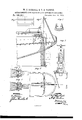
- Figure 1 is a side elevation, in section, on line aa; in Fig. 2.
- Fig. 2 is a plan.
- Figs. 3, 4., 5, 6, and 7 are detail views of various parts of the attachment.
- A is the stern-post of a vessel, to which plates of metal B are bolted. These plates are made thick on the outer or projecting part, and thin where they are bolted onto the sternpost, being wedge-shaped in section.
- the space between the plates B forms a dovetail.
- G G are guides, which are attached to the inner sides of theplates B. Near the keel a bar, a, connects the plates B. It is shouldered on the inside and riveted on the outside, to prevent the plates from spreading, and to form a rest for the movable part of the sternpost.
- D is the movable part of the sternpost, which is fitted into the dovetail, and on the guides between the plates B.
- the rudder-stock b is attached in the ordinary way.
- a square hole is made through each of the plates B, through which an iron or steel pin, 0, is passed over the upper end of themovable part ofthe stern-post.
- This pin is provided with a head, which rests against one of the plates B, and is slotted at the other end, and receives a key, which prevents the plates from spreading, and also holds the rudder down.
- the guide E has the same internal form as the guide on the stern-post, and is hinged to the stern-post at d, or to the section F.
- the guide E is attached to the guide E by means of the bolts 9.
- the guide E is also provided with hook-braces h h.
- Shears H are placed at the stern of the vessel in such a position as to hold the tackle 0 over the stern-post.
- An eye, 70 is attached to the upper end of the movable part of the sternpost, which is used in removing the rudder.
- the operation of our invention is as follows: Supposing a rudder to have been broken, it is put amidships.
- the hatch i is raised, and the port j is opened.
- the guide E and shears H are placed in position, and the tackle e is hooked to the movable part D.
- the steering-gear is loosened, the pin 0 removed, and the movable part I) and rudder I are drawn up together until the screwfin the yoke G will engage with a hole made in the rudder near the heel.
- the screw is then set down, making the rudder fast to the guide E.
- the tackle is now slackened, and the rudder and guide laid over on the deck.
- the screw fis loosened, and the yoke G is let down over the heel of the rudder.
- the rudder is then removed, and a new one put in its place in the guide.
- the yoke G is raised, and the screwfis turned down, clamping the rudder to the guide.
- the guide E and rudder are raised into a vertical position by the tackle.
- the braces h h are made fast to eyebolts in the deck.
- the screw f is loosened, and the rudder lowered into its position, the part 1) following the guide in the stern-post.
- the pin 0 is now replaced, the port 9' and hatch i are closed, and the steering-gear rigged.
- the shears H and guide E are cleared from the deck after replacing the rudder.
Landscapes
- Chemical & Material Sciences (AREA)
- Engineering & Computer Science (AREA)
- Combustion & Propulsion (AREA)
- Mechanical Engineering (AREA)
- Ocean & Marine Engineering (AREA)
- Hinges (AREA)
Description
W 4, BUSHALL & T. E. PARKIN. ATTACHMENTS FOR RAISING AND LOWERIN'G RUDDER Sf Patented Dec. 12', 1876.
momm rrn s WILLIAM BUSHALL AND THOMAS E. PARKIN, OF BEAUFORT, N. G.
IMPROVEMENT IN ATTACHMENTS FOR RAISING AND LOWERING RUDDERS.
Specification forming part of Letters Patent No. 185,291, dated December 12, 1876; application tiled July 1, 1876.
To all whom it may concern Be it known that we, WILLIAM J. BUSH- ALL and THOMAS E. PARKIN, of Beaufort, in
the county of Garteret and State of North Carolina, have invented a new and Improved Rudder Attachment, of which the following is a specification:
Figure 1 is a side elevation, in section, on line aa; in Fig. 2. Fig. 2 is a plan. Figs. 3, 4., 5, 6, and 7 are detail views of various parts of the attachment.
Similar letters of reference indicate corresponding parts.
The invention will first be described in connection with the drawing, and then pointed out in the claims.
A is the stern-post of a vessel, to which plates of metal B are bolted. These plates are made thick on the outer or projecting part, and thin where they are bolted onto the sternpost, being wedge-shaped in section. The space between the plates B forms a dovetail. G G are guides, which are attached to the inner sides of theplates B. Near the keel a bar, a, connects the plates B. It is shouldered on the inside and riveted on the outside, to prevent the plates from spreading, and to form a rest for the movable part of the sternpost. D is the movable part of the sternpost, which is fitted into the dovetail, and on the guides between the plates B. To this part of the stern-post the rudder-stock b is attached in the ordinary way. At the top of the side plates, near the deck, a square hole is made through each of the plates B, through which an iron or steel pin, 0, is passed over the upper end of themovable part ofthe stern-post. This pin is provided with a head, which rests against one of the plates B, and is slotted at the other end, and receives a key, which prevents the plates from spreading, and also holds the rudder down.
It is designed to have the spare rudder which the vessel will carry provided with a duplicate of the movable part of the sternpost D, and also with the appropriate steering-gear, so that in case of emergency no time need be lost in applying these parts.
The guide E has the same internal form as the guide on the stern-post, and is hinged to the stern-post at d, or to the section F. A
. yoke, Gr, provided with the clamping-screw f,
is attached to the guide E by means of the bolts 9. The guide E is also provided with hook-braces h h.
When the vessel has saloons which run back so that it is inconvenient to use the guide E when hinged directly to the stern-post, a short section, F, having the same internal form as the guide, is hinged to the stern-post, and the guide E ishinged to the upper end of it, as in Fig.1 in the drawing. When the saloon runs to the stern the guide on the sternpost is lengthened so that it will reach above the saloon, and the guide E is hinged to this extension, and used as above described.
Shears H are placed at the stern of the vessel in such a position as to hold the tackle 0 over the stern-post. An eye, 70, is attached to the upper end of the movable part of the sternpost, which is used in removing the rudder.
The operation of our invention is as follows: Supposing a rudder to have been broken, it is put amidships. The hatch i is raised, and the port j is opened. The guide E and shears H are placed in position, and the tackle e is hooked to the movable part D. The steering-gear is loosened, the pin 0 removed, and the movable part I) and rudder I are drawn up together until the screwfin the yoke G will engage with a hole made in the rudder near the heel. The screw is then set down, making the rudder fast to the guide E. The tackle is now slackened, and the rudder and guide laid over on the deck. The screw fis loosened, and the yoke G is let down over the heel of the rudder. The rudder is then removed, and a new one put in its place in the guide. The yoke G is raised, and the screwfis turned down, clamping the rudder to the guide. The guide E and rudder are raised into a vertical position by the tackle. The braces h h are made fast to eyebolts in the deck. The screw f is loosened, and the rudder lowered into its position, the part 1) following the guide in the stern-post. The pin 0 is now replaced, the port 9' and hatch i are closed, and the steering-gear rigged. The shears H and guide E are cleared from the deck after replacing the rudder.
The advantage claimed for our improvement is, the facility with which a disabled rudder a a I 1s5,291
may be removed and another put in its place. By the use of our invention the disasters which occur from a broken or disabled rudder may be avoided, as it requires but a few moments, under any circumstances, to remove a broken rudder and replace it with a whole one.
We do not limit or confine ourselves, to the exact form, position, or construction of the parts composing our improvement, as they may be varied without departing from our invention.
Having thus described our invention, we claim as new and desire to secure by Letters Patent- 1. The combination of the hinged guide E, stern-post A,'and removable part D, as shown and described.
2. The combination of the guide E, section F, stern-post A, and removable part D, as specified.
3. The combination of the yoke G, screw f, and guide E, as shown and described.
WILLIAM J. BUSHALL.
THOMAS E. PARKIN.
-Witnesses: A. G. DAVIS, HY. WATERS.
Publications (1)
| Publication Number | Publication Date |
|---|---|
| US185291A true US185291A (en) | 1876-12-12 |
Family
ID=2254696
Family Applications (1)
| Application Number | Title | Priority Date | Filing Date |
|---|---|---|---|
| US185291D Expired - Lifetime US185291A (en) | Improvement in attachments for raising and lowering rudders |
Country Status (1)
| Country | Link |
|---|---|
| US (1) | US185291A (en) |
-
0
- US US185291D patent/US185291A/en not_active Expired - Lifetime
Similar Documents
| Publication | Publication Date | Title |
|---|---|---|
| EP3696074B1 (en) | Catamaran type vessel | |
| US559983A (en) | mclean | |
| US185291A (en) | Improvement in attachments for raising and lowering rudders | |
| US259308A (en) | Center-board for vessels | |
| US176285A (en) | Improvement in means of attachment of ships rudders | |
| US277146A (en) | Detachable cover for boats | |
| US326985A (en) | Adjust | |
| US258375A (en) | Thomas clapham | |
| US55053A (en) | Improved apparatus for lowering shipsj boats | |
| US208750A (en) | Improvement in adjustable center-boards | |
| US36482A (en) | Rigging and spars oe ships and other navigable vessels | |
| US2336A (en) | Manner of constructing- steam vessels to prevent them from sinking | |
| US45039A (en) | Improved sectional boat | |
| US748618A (en) | Device for mooring and warping vessels | |
| US167439A (en) | Improvement in hinged masts for boats | |
| US1084310A (en) | Ship's davits. | |
| US20751A (en) | Territory | |
| US1118499A (en) | Apparatus for launching life-boats from decks of ships. | |
| US67433A (en) | Peters | |
| US1078080A (en) | Davit. | |
| US401373A (en) | Ship s sail | |
| US621611A (en) | Henry j | |
| US1363961A (en) | Rudder | |
| US60966A (en) | Improved boat-detaching tackle | |
| USRE5512E (en) | Improvement in boat-lowering apparatus |