US1852914A - Collapsible or extensible table - Google Patents
Collapsible or extensible table Download PDFInfo
- Publication number
- US1852914A US1852914A US535497A US53549731A US1852914A US 1852914 A US1852914 A US 1852914A US 535497 A US535497 A US 535497A US 53549731 A US53549731 A US 53549731A US 1852914 A US1852914 A US 1852914A
- Authority
- US
- United States
- Prior art keywords
- boards
- hinged
- cross
- board
- legs
- Prior art date
- Legal status (The legal status is an assumption and is not a legal conclusion. Google has not performed a legal analysis and makes no representation as to the accuracy of the status listed.)
- Expired - Lifetime
Links
Images


Classifications
-
- A—HUMAN NECESSITIES
- A47—FURNITURE; DOMESTIC ARTICLES OR APPLIANCES; COFFEE MILLS; SPICE MILLS; SUCTION CLEANERS IN GENERAL
- A47B—TABLES; DESKS; OFFICE FURNITURE; CABINETS; DRAWERS; GENERAL DETAILS OF FURNITURE
- A47B1/00—Extensible tables
- A47B1/08—Extensible tables with extensible frames or with additional legs
Definitions
- This invention relates tocertain lnew and useful improvements in collapsible or extensionltables.
- the primaryobject of the invention is to provide a collapsible or extension tablethat of space and Which'wh'en extended for-use provides a substantial structure.y
- a further object of the invention is to provide a collapsible or extension table wherein side boards formed of hingedly connected sections are hingedly connected at their outer ends to supporting legs with' spring devices associated with the latter connectionsautoymatically eiecting opening movement or extension of the hinged side boardswhenthe structure is extendedinto table'formation.
- a still further object of the invention is to provide a? table kstructure of the foregoing character wherein means is provided for association with the supporting legs when the device is in Acollapsed condition for restraining the structure from opening ⁇ movement by the spring devices associated therewith.
- Another obj ect of fthe invention is to pro- ⁇ Y vide -an'operating table associated with the adjacent hinged ends ofA the side board sec-y tions to effect collapsing ofthe table structure with a inanuallyrrotated reel; or drum upon which the 'cableis wound when the table is ⁇ to be collapsed.
- the saine k consists in the novel forni,l combination and arrangement of parts hereinafter more fully deings and claimed.;Vv i
- Figure 8 is a top plan view ot the table frame with the table topillnstrated by dotted lines and showing ⁇ springs associated with the hinged connection between the side board talnected sections thereof;
- Y Y n Figure' is a topl plan view showingy the"y table frame partly collapsed with the table top removed;
- f z Figure 6 is a top planview of the tablein Y fully collapsedcondition and so retained by' straps engaged with adjacentlyj positioned supporting legs;
- Y Figure 7 is aside elevational view of the ⁇ table in collapsed condition;
- I Figure 8 is an end elevational view ofthe table showingthe cable, drum and ratchet mechanism associated therewith; v
- Figure 9 isafragmentary bottoni plan view of the table topshowing the hingedly confV Figure 10 is an end elevational view, ⁇ part ly 1n section ⁇ of the table top in folded condi- ⁇ V tion; i
- Figure 11 is a. cross-sectional view'taken on line 114-11 of Figure 2, ⁇ showing' a guide pul-V 7 ley for lthe cable of the table with cable journa-lled on the'end'board;
- Figure12 is a cross-sectional view taken on Y journalled iny an end board" the winding drum for the Y form of intermediately positioned cross boards for the free passage of the table col#l lapsing cable;
- I Figure 13 is a fragmentary end elevational" view of another form of operatingineans for S the cablewinding drum;
- j 1 1 Figure 14 is a fragmentary horizontal Vsec- Figure 15 is a detail sectional viewgtaken on line 15j-15 of Figure 13;
- 9 Figure 16 is a fragme'ntai'yA longitudinal sec-tionalr View, showing spring devices env- ⁇ gagedrwiththe outer'ends of the hingedly connected side boards;
- Figure 17 is a detail sectional vView taken 9 on line 17-17vof Figure 16, showing a, springV associated with a corner leg ofa'table andiy the adjacentsection of a side board; c
- Figure 18' is a detail sectional view taken: on line 18-18'of' Figure 16, showing the 1 with an intermediate leg spring associated with adjacent 1n a supporting leg to permit positioning of a retaining pin for the spring device;
- Figure 20 is a detail sectional view taken on line 20-20 of Figure 18.
- the table structure as shown in Figures 1 to 5 comprises end boards 1 and 2 carrying end legs 3 and interinediately positioned cross-boards 4 carrying end legs 5, all of said legs being provided with casters or rollers.
- Side boards for the table structure are formed of sections 7 which are hingedly connected together at their adjacent ends as at 8, while the outer end oli each section is hingedly connected as at 9 to an adjacent leg, the hinge connection between the leg'3 and the adjacent side hoard section 7 being designated by the reference character 9a, all of said hinges comprising vertical pintles whereby the side board sections are movable in horizontal planes with the hinge connections 8 movable toward and away from each otheras shown in Figure 5.
- each hinge member 8 includes strap portions 10 and 11 respectively secured to a section of a side board at the adjacent side of an intermediate cross-board 4 and each end of the cross board terminates in spaced relation to the upper ends of the intermediate legs 5 to provide apocket 12 registering with the side pocket 13 inthe upper end of the leg 5, said leg above and below the pocket 13 having openings 14v therein as illustrated.
- a coiled spring 15- is located in the registering pockets 12. and 13 and is retained in position by the pin 16 seated in the leg openings 14, the free ends 17 of the spring extending through openings 18 in the hinge straps 11 for engagement with adjacent sections of the side boards 7 and operating normally to move the side boards to an open extended position.
- Similar spring is associated with the hinge connection 9a betweenvthe end side board section 7 and corner leg,3 as shown in Figures 17 and 19, the hinge 9a including straps 19 and 20 respectively secured to the side board section and leg, the hinge strap 20 having an opening therein registering with the pocket 21 in the leg that rreceives the coil spring 15a. one end 17a thereof being engaged with the side board section, while its other end 17?) is anchored in the corner leg as illustrated.
- the table structure is automatically eX- tended by the spring devices associated with the spring hinge connections between the side boards and the supporting legs and to collapse the table, an operating, cable is associated therewith.
- nr cable 22 is anchored at one end as at 23 to the inner face of the end board 1 intermediate 'the ends thereof, the cable being threaded through eyelets 4 carried by corresponding ends of side board sections 7 adjacent their hinge connection 8, the cross boards 4 being cut awa-y as at 4a as shown in Figure 12 to permit unobstructed passage of the cable therethrough, the cable being operatively engaged with corresponding ends oi each pair of side board sections as illustrated and finally passing through an opening in the end board 2 and guided by a pulley 25 journalled in said opening.
- a windin g drum 26 is journalled upon the outer face of the end board 2 and to which the adjacent end of the cable 22 is attached, the drum carrying a ratchet wheel 27 to be engaged by a pawl'28 pivoted on the end board 2 and said drum and ratchet wheel are operated by the crank handle 29.
- the drum 26 is rotated by the crank handle 29 to wind the cable 22 thereon, the cable moving through the guide eyelets 24 carried by the side sections 7 causing said side boards to move on their hinge connections against the tension of the springs associated therewith, the adjacent hinged ends 8 of the side board sections moving inwardly while the cross boards 4 move toward each other, the cross board 1 approaching the end board 2.
- the table frame finally assuming the formation shown in Figures 6 and 7 and there retained against the tension of the springs associated with the hinge connections by the pawl and ratchet mechanism associated with the winding drum 26.
- means which include a pin 30 projecting outwardly from each cross board and end board to be engaged by a strap 31 having openings therein to receive the pin thereby securing a locking closure for the table frame in collapsed condition.
- the straps 31 are removed and upon releasing the pawl 28 from the ratchet wheel 27, the springs associated with the hinge connection between the side sections and Ylegs automatically extends the table frame to the iiull line position shown in Figure 3 for reception of the table top.
- the table top is composed of sections 33 hinged together' at adjacent edges 34 and unfolded from the position shown in Figure 10 is placed upon the table frame and to temporarily secure the table top in position, the end boards of the sectional top are each provided with an opening 35, that receives the upstanding pin 36 rising from the upper edges of the end boards 1 and 2 as shown in Figures 6 to 8. lVhen the table is to be collapsed, the sectional top isdisengaged therein FigurexlO.
- Aspringpressed pawl 42 is carried by the sprocket wheel 40andis engaged with the ratchet 'wheel' 89 at one side thereof and an- Y otherpawl 43 carried by the end board 2 is engagedwith the ratchetwheel 39 at theopposite yside thereof.
- the sprocket chain 44 that passes kover ⁇ the sprocket Wheel 40 is at-v tachedL to oney end 'of a coil spring 45 that is anchored as at 46 to an end leg B'while the other; endof the sprocket chain that depends from the end board v2 vcarries a stirrnp 47.
- a foot is placed in the stirrup 47 to pull the sprocket chain 44 againstthe tension-ofthe spring 45 for rotate, Ying; the sprocket, Wheel and cable drum 38 Y 252 throughthe medium of the pawl 42 carried by lthesprocket wheel that engages with thek ratchet wheel .39,2 the pawl 43 holding the cable drum V'and ratchet wheel in shifted position ywhile lthe pawlV 42 tion of the sprocket wheel on the ⁇ intnence of the spring and sprocket chain 44, repeated operation of depressing the stirrup 47 accomplishing a complete collapsing movement ofthe table frame.
- both the pawls 42'and 43 may be disengaged from the ratchet .wheel 39 and the spring devices associated with "the hinged connections between the side boards and legs of the table operate to extend the table frame.
- a table Y matically extending fthetable, a sectionalitable topy having interlocking connectionsat its ends with the end cross-boards, a pin :pro-k jecting from each end 'ofthe cross boards, and a strap engaged with the pins for holding the table in collapsed condition.
- the table g collapsing rmeans includinga cable anchored at one end to an end cross board and havingL take-up engagement With adjacent ends of lhe hinged side board sections.y
- each leg having a pocket therein, a coil spring anchored in the pocket with its ends engaged with a side board section for normally holding the side board sections in extended table forming position, means for collapsing the table and moving thef'adjacent hinged ends of the side board sections toward each other and the cross boards in adjacent relations, and means interlockingly engagedr with the ends of the cross boards for holding the table in collapsed condition.
- the table collapsing means including a cable anchored at one end to an end cross board and having take-up engagement with adjacent ends of the hinged side board sections.
- each leg having a pocket therein, a coil spring anchored in the pocket with its ends engaged with a side board section for normally holding the side board sections in extended table forming position, means for collapsing the table and moving the adjacent hinged ends of the ,side board sections toward each other and the cross boards in adjacent relations, the table collapsing means including a cable anchored at one end to an end cross board and having take-up engagement with adjacent ends of the hinged side board sections, a cable drum journalled on the other end cross board upon which the cable is wound and pawl andratchet'mechanism associated with the cable drum.
- a table of the character described supporting legs, cross boards between the legs, hinged sectional side boards hinged to the legs at each side of the table and collapsible in a horizontal plane, each leg having a pocket therein, a coil spring anchored in the pocket with its ends engaged with a side board section for normally holding the side board sections in extended table forming position, means for collapsing the table and moving the adjacent hinged ends of the side board sections toward each other and the cross boards in adjacent relations, and means interlockingly engaged with the ends of the cross boards for holding the table in collapsed condition, the table collapsing means including a cable anchored at one end to an end cross board and having take-up engagement with adjacent ends of the hinged side board sections, a cable drum journalled on 65 the other end cross board upon which the cable is wound and pawl and ratchet mecha;- nism associated with the cable drum.
- a table of the character described supporting legs, cross boards between the legs, hinged sectional side boards hinged to the legs at each side of the table and collapsi ble in a horizontal plane, each leg havingr a pocket therein, a coil spring anchored inv the pocket with its ends engaged with a sideboard section for normally holding the side board sections in extended table forming position, means for collapsing the table and moving the adjacent hinged ends of the side board sections toward each other and the cross boards in adjacent relations, the table collapsing means including a cable anchored at one end to an end cross board and having ⁇ take-up engagement with adjacent ends of the hinged side board sections, a cable drum journalled on the other end cross board upon' which the cable is wound, a ratchet Wheel rigid with the drinn, a pivoted pawl on the end board engageable with the ratchet wheel, a sprocket wheel adjacent the ratchet wheel, a pawl on the sprocket wheel engageable with the
- each leg having a pocket therein, a coil spring anchored in the pocket with its ends engaged with a side board section for normally holding the side board sections in extended table forming position, means for collapsing the table and moving the adjacent hinged ends of the side board sections toward each other and the cross boards in adjacent relations, and means interlockingly engaged with the ends of the cross boards for holding the table in collapsed condition, the table collapsing means including a.
- a ratchet wheel rigid with the drum, a pivoted pawl on the end board engageable with the ratchet wheel, a sprocket wheel adjacent the ratchet wheel, a pawl on the sprocket wheel engageable with the ratchet wheel and a tensioned sprocket chain for operating the sprocket wheel and having a stirrup at one end to facilitate operation thereof.
Description
Apri15, 1932. A, BERTA 1,852,914
COLLAPSIBLE OR EXTENSIBLE TABLE Filed May e, 1951 Y 4 sheets-sheet 1 @haarden .3e/oa.
amg/131 5 -5, l1932. A` BERTA l 1,852,914
COLLAPSIBLE OR EXTENSIBLE TABLE Filed May 6, 1951 4 Sheets-Sheet 2 April 5, 1932. A BERTA 1,852,914
GOLLAPSIBLE 0R EXTENSIBLE TABLE Filed May 6, 1951 4 sheeVts-Smeec 3 April 5, 1932. A, BERTA `1,85?,914
COLLAPSIBLE OR EXTENSIBLE TABLE Filed May e, 1931 l 4 sheets-sheet 4 flemnde'r (Berta.
- when folded or collapsed occupies a minimum kPatented Apr. 5,y `193.2.
strates COLLAPSIBLE on EXTENSIBLE TABLE i Application sied May 6,1931. serial 110.535,497. y
This invention relates tocertain lnew and useful improvements in collapsible or extensionltables.Y f
f The primaryobject of the invention is to provide a collapsible or extension tablethat of space and Which'wh'en extended for-use provides a substantial structure.y
A further object of the invention `is to provide a collapsible or extension table wherein side boards formed of hingedly connected sections are hingedly connected at their outer ends to supporting legs with' spring devices associated with the latter connectionsautoymatically eiecting opening movement or extension of the hinged side boardswhenthe structure is extendedinto table'formation.
A still further object of the invention is to provide a? table kstructure of the foregoing character wherein means is provided for association with the supporting legs when the device is in Acollapsed condition for restraining the structure from opening `movement by the spring devices associated therewith.
Another obj ect of fthe inventionis to pro-` Y vide -an'operating table associated with the adjacent hinged ends ofA the side board sec-y tions to effect collapsing ofthe table structure with a inanuallyrrotated reel; or drum upon which the 'cableis wound when the table is `to be collapsed. i
liVithvthefabove rand other objects in view that will'becomeapparent as the nature of the invention is better understood, the saine kconsists in the novel forni,l combination and arrangement of parts hereinafter more fully deings and claimed.;Vv i
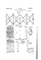
In the drawings :Y- Figure 1 isa top plan view of the collapsible or extensible tableconstructed in accordance with the present invention; ,n
,Figure 2 yisV a sideV elevational view-fof the scribed` shown' in the accompanying drawe Y i f tional viewtaken onlineelfll-of Figure'l;
f table in extended condition showingr the suns porting legs and the side boards formed of hingedly connected sections; Figure 8 is a top plan view ot the table frame with the table topillnstrated by dotted lines and showing` springs associated with the hinged connection between the side board talnected sections thereof;
yline l1.2--12 of Figure 2 showing a skeletonv ble legs and the cable `for effecting collapsing of the table associated with the adjacent t hinged ends of the side board sections;
table; Y Y n Figure' is a topl plan view showingy the"y table frame partly collapsed with the table top removed; f z Figure 6 is a top planview of the tablein Y fully collapsedcondition and so retained by' straps engaged with adjacentlyj positioned supporting legs; .Y Figure 7 is aside elevational view of the` table in collapsed condition; I Figure 8 is an end elevational view ofthe table showingthe cable, drum and ratchet mechanism associated therewith; v
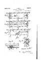
Figure 9 isafragmentary bottoni plan view of the table topshowing the hingedly confV Figure 10 is an end elevational view,`part ly 1n section `of the table top in folded condi-` V tion; i
Figure 11 is a. cross-sectional view'taken on line 114-11 of Figure 2, `showing' a guide pul-V 7 ley for lthe cable of the table with cable journa-lled on the'end'board;
Figure12 is a cross-sectional view taken on Y journalled iny an end board" the winding drum for the Y form of intermediately positioned cross boards for the free passage of the table col#l lapsing cable; I Figure 13 is a fragmentary end elevational" view of another form of operatingineans for S the cablewinding drum; j 1 1 Figure 14 is a fragmentary horizontal Vsec- Figure 15 is a detail sectional viewgtaken on line 15j-15 of Figure 13; 9 Figure 16 is a fragme'ntai'yA longitudinal sec-tionalr View, showing spring devices env-` gagedrwiththe outer'ends of the hingedly connected side boards;
Figure 17 is a detail sectional vView taken 9 on line 17-17vof Figure 16, showing a, springV associated with a corner leg ofa'table andiy the adjacentsection of a side board; c
Figure 18'is a detail sectional view taken: on line 18-18'of'Figure 16, showing the 1 with an intermediate leg spring associated with adjacent 1n a supporting leg to permit positioning of a retaining pin for the spring device; and
Figure 20 is a detail sectional view taken on line 20-20 of Figure 18.
Referring more in detail to the accompanying drawings, the table structure as shown in Figures 1 to 5 comprises end boards 1 and 2 carrying end legs 3 and interinediately positioned cross-boards 4 carrying end legs 5, all of said legs being provided with casters or rollers.k Side boards for the table structure are formed of sections 7 which are hingedly connected together at their adjacent ends as at 8, while the outer end oli each section is hingedly connected as at 9 to an adjacent leg, the hinge connection between the leg'3 and the adjacent side hoard section 7 being designated by the reference character 9a, all of said hinges comprising vertical pintles whereby the side board sections are movable in horizontal planes with the hinge connections 8 movable toward and away from each otheras shown in Figure 5.
As shown in Figures 16, 18 and 20, each hinge member 8 includes strap portions 10 and 11 respectively secured to a section of a side board at the adjacent side of an intermediate cross-board 4 and each end of the cross board terminates in spaced relation to the upper ends of the intermediate legs 5 to provide apocket 12 registering with the side pocket 13 inthe upper end of the leg 5, said leg above and below the pocket 13 having openings 14v therein as illustrated. A coiled spring 15-is located in the registering pockets 12. and 13 and is retained in position by the pin 16 seated in the leg openings 14, the free ends 17 of the spring extending through openings 18 in the hinge straps 11 for engagement with adjacent sections of the side boards 7 and operating normally to move the side boards to an open extended position. Similar spring is associated with the hinge connection 9a betweenvthe end side board section 7 and corner leg,3 as shown in Figures 17 and 19, the hinge 9a including straps 19 and 20 respectively secured to the side board section and leg, the hinge strap 20 having an opening therein registering with the pocket 21 in the leg that rreceives the coil spring 15a. one end 17a thereof being engaged with the side board section, while its other end 17?) is anchored in the corner leg as illustrated.
The table structure is automatically eX- tended by the spring devices associated with the spring hinge connections between the side boards and the supporting legs and to collapse the table, an operating, cable is associated therewith. As shown in Figures 3 and 5, acord, nr cable 22is anchored at one end as at 23 to the inner face of the end board 1 intermediate 'the ends thereof, the cable being threaded through eyelets 4 carried by corresponding ends of side board sections 7 adjacent their hinge connection 8, the cross boards 4 being cut awa-y as at 4a as shown in Figure 12 to permit unobstructed passage of the cable therethrough, the cable being operatively engaged with corresponding ends oi each pair of side board sections as illustrated and finally passing through an opening in the end board 2 and guided by a pulley 25 journalled in said opening.
As shown in Figures 8, 11 and 12, a windin g drum 26 is journalled upon the outer face of the end board 2 and to which the adjacent end of the cable 22 is attached, the drum carrying a ratchet wheel 27 to be engaged by a pawl'28 pivoted on the end board 2 and said drum and ratchet wheel are operated by the crank handle 29. Assuming that the table frame is in its extended position, and it is desired to collapse the same, the drum 26 is rotated by the crank handle 29 to wind the cable 22 thereon, the cable moving through the guide eyelets 24 carried by the side sections 7 causing said side boards to move on their hinge connections against the tension of the springs associated therewith, the adjacent hinged ends 8 of the side board sections moving inwardly while the cross boards 4 move toward each other, the cross board 1 approaching the end board 2. the table frame finally assuming the formation shown in Figures 6 and 7 and there retained against the tension of the springs associated with the hinge connections by the pawl and ratchet mechanism associated with the winding drum 26. To hold the table in collapsed condition, in addition to the pawl and ratchet mechanism, means are provided which include a pin 30 projecting outwardly from each cross board and end board to be engaged by a strap 31 having openings therein to receive the pin thereby securing a locking closure for the table frame in collapsed condition.
To extend the table frame, the straps 31 are removed and upon releasing the pawl 28 from the ratchet wheel 27, the springs associated with the hinge connection between the side sections and Ylegs automatically extends the table frame to the iiull line position shown in Figure 3 for reception of the table top.
The table top is composed of sections 33 hinged together' at adjacent edges 34 and unfolded from the position shown in Figure 10 is placed upon the table frame and to temporarily secure the table top in position, the end boards of the sectional top are each provided with an opening 35, that receives the upstanding pin 36 rising from the upper edges of the end boards 1 and 2 as shown in Figures 6 to 8. lVhen the table is to be collapsed, the sectional top isdisengaged therein FigurexlO.
V,Another formof cablev operatingmechan nism .is shownin FiguresV lgto the end board 2 of the table having a stub shat 87 exe.
tending `outwardly thereof for the rotatable support of ra dr'umBS witha ratchet wheel 39 forming a part" thereof .andalso a sprocketV wheel I40 retained uponthe shaft by the piny 41. Aspringpressed pawl 42 is carried by the sprocket wheel 40andis engaged with the ratchet 'wheel' 89 at one side thereof and an- Y otherpawl 43 carried by the end board 2 is engagedwith the ratchetwheel 39 at theopposite yside thereof. The sprocket chain 44 that passes kover `the sprocket Wheel 40 is at-v tachedL to oney end 'of a coil spring 45 that is anchored as at 46 to an end leg B'while the other; endof the sprocket chain that depends from the end board v2 vcarries a stirrnp 47. To collapse the table frame, a foot is placed in the stirrup 47 to pull the sprocket chain 44 againstthe tension-ofthe spring 45 for rotate, Ying; the sprocket, Wheel and cable drum 38 Y 252 throughthe medium of the pawl 42 carried by lthesprocket wheel that engages with thek ratchet wheel .39,2 the pawl 43 holding the cable drum V'and ratchet wheel in shifted position ywhile lthe pawlV 42 tion of the sprocket wheel on the `intnence of the spring and sprocket chain 44, repeated operation of depressing the stirrup 47 accomplishing a complete collapsing movement ofthe table frame. -When it is desired tol extend.y the `table frame, both the pawls 42'and 43 may be disengaged from the ratchet .wheel 39 and the spring devices associated with "the hinged connections between the side boards and legs of the table operate to extend the table frame. -Y
F rom the above'detailed description of the f invention, it is believed that the construction and operationthereof will at oncevbe apn parent, and while there are herein shown and described the preferred embodiments of*k ythe.
invention, it is nevertheless to be understood that minor changes may be kmade thereinV without departing'rfrom the spiritand scope of the invention as claimed. Y f
I claim v l. InA a table of the character described,-
supporting legs, cross boards'between the legs, hinged sectional side boards hinged to the legsfatveach side of theftable vand spring` devices associated with the hinge connections between Vthejlegs and side boards for antomatically extending lthe table, alpin projecting from each end of thecrossv boards, and a strap engaged with the pins iorholdingthe table in vcollapsed condition.
2. In a table of the 'character described,V
supporting legs,jcross boards between the legs, hinged sectional side boards hinged to the legs at each side of the table, spring' dei vices associated with the hinge connections permits reverse rotaf between the legs and ksideboards for faute matically extending the table, a cable associatediiwith the side board sections adjacent i the section hinges for collapsing thetable, a
pin.` projecting yfrom each endof the vcross boards, and ra strap engaged'with the pins'y tablein collapsed condition. olf-the character desoribed,1
supporting legs7 cross boardsbetween the 75 for holding the "3. In a table Y matically extending fthetable, a sectionalitable topy having interlocking connectionsat its ends with the end cross-boards, a pin :pro-k jecting from each end 'ofthe cross boards, and a strap engaged with the pins for holding the table in collapsed condition. i
supporting legs, cross boards between the f` the legs at each side of the table and collapsible in a horizontal planeyeach leg having a pocket therein, a coil spring anchored in the pocket withV its; ends yengaged with a side board section for normally holding the` side, board sections'in extended vtable-forming position, means tor" collapsing the table and moving the adjacenthingedends ofthe side board sections toward eachother andthe cross boards inadjacent relations, and means' interlockingly engaged with the ends of the cross boards for holding the tablein collapsed c'ondition.
6; In a table of the character described, supporting legs, cross boards between the legs, hinged sectional side boards hinged to the legs at each side of the table fand collapsi-k cross boards -in adjacent relations, the table g collapsing rmeans includinga cable anchored at one end to an end cross board and havingL take-up engagement With adjacent ends of lhe hinged side board sections.y
7. In a table of the character described, supporting legs, cross boards between the legs, hinged sectional side boards hinged to the legs at each side of the table and collapsiblein a horizontal plane, each leg having a pocket therein, a coil spring anchored in the pocket with its ends engaged with a side board section for normally holding the side board sections in extended table forming position, means for collapsing the table and moving thef'adjacent hinged ends of the side board sections toward each other and the cross boards in adjacent relations, and means interlockingly engagedr with the ends of the cross boards for holding the table in collapsed condition. the table collapsing means including a cable anchored at one end to an end cross board and having take-up engagement with adjacent ends of the hinged side board sections.
8. In a table of the character described, supporting legs, cross boards between the legs, hinged sectional side boards hinged to the legs at each side of the table and collapsible in a horizontal plane, each leg having a pocket therein, a coil spring anchored in the pocket with its ends engaged with a side board section for normally holding the side board sections in extended table forming position, means for collapsing the table and moving the adjacent hinged ends of the ,side board sections toward each other and the cross boards in adjacent relations, the table collapsing means including a cable anchored at one end to an end cross board and having take-up engagement with adjacent ends of the hinged side board sections, a cable drum journalled on the other end cross board upon which the cable is wound and pawl andratchet'mechanism associated with the cable drum.
9. In a table of the character described, supporting legs, cross boards between the legs, hinged sectional side boards hinged to the legs at each side of the table and collapsible in a horizontal plane, each leg having a pocket therein, a coil spring anchored in the pocket with its ends engaged with a side board section for normally holding the side board sections in extended table forming position, means for collapsing the table and moving the adjacent hinged ends of the side board sections toward each other and the cross boards in adjacent relations, and means interlockingly engaged with the ends of the cross boards for holding the table in collapsed condition, the table collapsing means including a cable anchored at one end to an end cross board and having take-up engagement with adjacent ends of the hinged side board sections, a cable drum journalled on 65 the other end cross board upon which the cable is wound and pawl and ratchet mecha;- nism associated with the cable drum.
10. In a table of the character described, supporting legs, cross boards between the legs, hinged sectional side boards hinged to the legs at each side of the table and collapsi ble in a horizontal plane, each leg havingr a pocket therein, a coil spring anchored inv the pocket with its ends engaged with a sideboard section for normally holding the side board sections in extended table forming position, means for collapsing the table and moving the adjacent hinged ends of the side board sections toward each other and the cross boards in adjacent relations, the table collapsing means including a cable anchored at one end to an end cross board and having` take-up engagement with adjacent ends of the hinged side board sections, a cable drum journalled on the other end cross board upon' which the cable is wound, a ratchet Wheel rigid with the drinn, a pivoted pawl on the end board engageable with the ratchet wheel, a sprocket wheel adjacent the ratchet wheel, a pawl on the sprocket wheel engageable with the ratchet wheel, and a tensioned sprocket chain for operating the sprocket Wheel and having a stirrup at one end to facilitate operation thereof.
l1.. In a table of the character described, supporting legs, cross boards between the legs, hinged sectional side boards hinged to the legs at each side of the table andcollapsible in a horizontal plane, each leg hav ing a pocket therein, a coil spring anchored in the pocket with its ends engaged with a side board section for normally holding the side board sections in extended table forming position, means for collapsing the table and moving the adjacent hinged ends of the side board sections toward each other and the cross boards in adjacent relations, and means interlockingly engaged with the ends of the cross boards for holding the table in collapsed condition, the table collapsing means including a. cable anchored at one end to an end cross board and having take-up engagement with adjacent ends of the hinged side board sections, on the other end cross board upon which the cable is wound, a ratchet wheel rigid with the drum, a pivoted pawl on the end board engageable with the ratchet wheel, a sprocket wheel adjacent the ratchet wheel, a pawl on the sprocket wheel engageable with the ratchet wheel and a tensioned sprocket chain for operating the sprocket wheel and having a stirrup at one end to facilitate operation thereof.
In testimony whereof I aHiX my signature.
ALEXANDER BERTA.
a cable drum journalled
Priority Applications (1)
| Application Number | Priority Date | Filing Date | Title |
|---|---|---|---|
| US535497A US1852914A (en) | 1931-05-06 | 1931-05-06 | Collapsible or extensible table |
Applications Claiming Priority (1)
| Application Number | Priority Date | Filing Date | Title |
|---|---|---|---|
| US535497A US1852914A (en) | 1931-05-06 | 1931-05-06 | Collapsible or extensible table |
Publications (1)
| Publication Number | Publication Date |
|---|---|
| US1852914A true US1852914A (en) | 1932-04-05 |
Family
ID=24134491
Family Applications (1)
| Application Number | Title | Priority Date | Filing Date |
|---|---|---|---|
| US535497A Expired - Lifetime US1852914A (en) | 1931-05-06 | 1931-05-06 | Collapsible or extensible table |
Country Status (1)
| Country | Link |
|---|---|
| US (1) | US1852914A (en) |
Cited By (4)
| Publication number | Priority date | Publication date | Assignee | Title |
|---|---|---|---|---|
| US3091816A (en) * | 1960-09-07 | 1963-06-04 | Wayne Iron Works | Folding stages |
| WO1990008489A1 (en) * | 1989-02-06 | 1990-08-09 | Bjarne Carl Heinze | Structure comprising vertical supports for holding of a horizontal upper part |
| WO1991003965A1 (en) * | 1989-09-18 | 1991-04-04 | Giuseppe Baggiani | Furnishing element with foldable panels |
| US20070277710A1 (en) * | 2006-06-06 | 2007-12-06 | Gray Daniel G | Modular conference table |
-
1931
- 1931-05-06 US US535497A patent/US1852914A/en not_active Expired - Lifetime
Cited By (5)
| Publication number | Priority date | Publication date | Assignee | Title |
|---|---|---|---|---|
| US3091816A (en) * | 1960-09-07 | 1963-06-04 | Wayne Iron Works | Folding stages |
| WO1990008489A1 (en) * | 1989-02-06 | 1990-08-09 | Bjarne Carl Heinze | Structure comprising vertical supports for holding of a horizontal upper part |
| WO1991003965A1 (en) * | 1989-09-18 | 1991-04-04 | Giuseppe Baggiani | Furnishing element with foldable panels |
| US5311826A (en) * | 1989-09-18 | 1994-05-17 | Giuseppe Baggiani | Furnishing element with foldable panels |
| US20070277710A1 (en) * | 2006-06-06 | 2007-12-06 | Gray Daniel G | Modular conference table |
Similar Documents
| Publication | Publication Date | Title |
|---|---|---|
| US1647679A (en) | Collapsible hatbox | |
| US2908021A (en) | Playyard | |
| US2254939A (en) | Collapsible structure | |
| US1852914A (en) | Collapsible or extensible table | |
| US3800341A (en) | Portable collapsible combination crib and playpen | |
| US2167342A (en) | Folding table | |
| US2558995A (en) | Bag stool combination | |
| US3010719A (en) | Foldable rocking device | |
| US1340694A (en) | Child's folding combined bed and coop | |
| US2021494A (en) | Folding ladder | |
| US2630639A (en) | Collapsible ironing board | |
| US732740A (en) | Exercising apparatus. | |
| US1742137A (en) | Collapsible gocart | |
| US1615265A (en) | Collapsible garment trunk | |
| US2776441A (en) | Collapsible child's bed | |
| US2079737A (en) | Table | |
| US960281A (en) | Tourist's bed. | |
| US1545446A (en) | Folding bathtub support | |
| US2809382A (en) | Baby playpen | |
| US1004796A (en) | Canopy-couch. | |
| US1120480A (en) | Combined bed and trunk. | |
| US2137229A (en) | Collapsible table | |
| US1130777A (en) | Collapsible and portable bath-tub. | |
| US2371481A (en) | Combination trunk and cot | |
| US947341A (en) | Tent-bed. |