US1852907A - Brake lining stretcher - Google Patents
Brake lining stretcher Download PDFInfo
- Publication number
- US1852907A US1852907A US475818A US47581830A US1852907A US 1852907 A US1852907 A US 1852907A US 475818 A US475818 A US 475818A US 47581830 A US47581830 A US 47581830A US 1852907 A US1852907 A US 1852907A
- Authority
- US
- United States
- Prior art keywords
- lining
- brake
- brake lining
- stretcher
- brake shoe
- Prior art date
- Legal status (The legal status is an assumption and is not a legal conclusion. Google has not performed a legal analysis and makes no representation as to the accuracy of the status listed.)
- Expired - Lifetime
Links
- 241001585751 Paenibacillus phage Tripp Species 0.000 description 2
- 238000010276 construction Methods 0.000 description 2
- 102100025250 C-X-C motif chemokine 14 Human genes 0.000 description 1
- 101000858068 Homo sapiens C-X-C motif chemokine 14 Proteins 0.000 description 1
- 101100006982 Mus musculus Ppcdc gene Proteins 0.000 description 1
- 210000005069 ears Anatomy 0.000 description 1
- 239000012634 fragment Substances 0.000 description 1
- 238000004519 manufacturing process Methods 0.000 description 1
Images
Classifications
-
- B—PERFORMING OPERATIONS; TRANSPORTING
- B25—HAND TOOLS; PORTABLE POWER-DRIVEN TOOLS; MANIPULATORS
- B25B—TOOLS OR BENCH DEVICES NOT OTHERWISE PROVIDED FOR, FOR FASTENING, CONNECTING, DISENGAGING OR HOLDING
- B25B27/00—Hand tools, specially adapted for fitting together or separating parts or objects whether or not involving some deformation, not otherwise provided for
- B25B27/0021—Tools for bonding or debonding brake linings
-
- Y—GENERAL TAGGING OF NEW TECHNOLOGICAL DEVELOPMENTS; GENERAL TAGGING OF CROSS-SECTIONAL TECHNOLOGIES SPANNING OVER SEVERAL SECTIONS OF THE IPC; TECHNICAL SUBJECTS COVERED BY FORMER USPC CROSS-REFERENCE ART COLLECTIONS [XRACs] AND DIGESTS
- Y10—TECHNICAL SUBJECTS COVERED BY FORMER USPC
- Y10T—TECHNICAL SUBJECTS COVERED BY FORMER US CLASSIFICATION
- Y10T29/00—Metal working
- Y10T29/53—Means to assemble or disassemble
- Y10T29/53648—Brake lining to brake shoe
Definitions
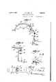
- This invention relates to a device for stretching brake linings in association with brake shoes, and has for an object. the provision of a device adapted to be anchored to 5 a brake lining and associated with means whereby manipulation of a brake shoe results in stretching the lining in order'that said lining may be secured in proper condition on the said shoe.
- the invention consists in the details of construction, and in the arrangement and combination of parts to be hereinafter more fully set forth and claimed.
- Figure 2 illustrates a perspective view of the bracket member of the invention
- Figure 3 illustrates a perspective view of a fragment of another part of the invention
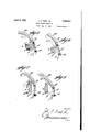
- Figure 4 illustrates a plan View of the bracket shown in Figure 2 and Figures 5, 6, 7 and 8 are views in elevation illustrating different means of utilizing the invention in association with braking elements of various types.
- Any suitable bench or base 5 may be employed as a; support for the -angularl-y dis- :posed-baseG of the standard 7 tha't-tern iinates -i in a horizontally d-isposed; head 8,---WhOS6 upper surface is provided with serrations t).
- Guiding' -lugs '10 and 11-- are formed intefl- 5a gr -alywith the standardandheadand-they,are in spaced relation to eachbther toproduce ta clearance,; as at 12.' 1
- the saidmember is shown as hav-' ing a handle 23 which :iS-cur-ved in order-that it-will conformapproximately to the curvature 24 of the surface of thebrake shoe to which the lining is applied; c
- the brake shoe is usually provided with a lining secured at one end, as stated, and the chain connected to the member 16 is threaded through the aperture of the lug 13 and one of the links of the chain is seated in the space between the furcations of the lug 14 with the end of the link immediately below the one in the recess engaging the under surface of the lug 14.
- the chain is then placed in the position in which it is shown in Figure l and the spurs are imbedded in the brake lining when one end of the brake shoe is in engagement with the serrations 9 or one of them.
- interposed supports or filling blocks such as a, b, a and d may be employed and these may be of diflerent dimensions to suit particular requirements.
- the filling blocks may of course be used in other ways than those specifically illustrated but those shown will serve to disclose the diversity of use of which the invention is capable.
- the device can be manipulated so as to facilitate the stretching and securing of a brake lining, as compared with devices now in common use or known in the art.
- a suitably anchored bracket having an approximately horizontally disposed portion with a serrated surface on which an end of a brake shoe may be oscillative, a member having spurs adapted to be imbedded in an end of a lining toward the end of a brake shoe which is oscillatively supported, the said lining being secured to the brake shoe near its opposite end, means for retaining the member in operative relation to the lining, a chain connected tothe first mentioned member, an apertured lug on the bracket through which the (:0 chain is threaded, and a lug therebelow for engaging the chain and operative to restrain the movement of the first mentioned member.
Landscapes
- Engineering & Computer Science (AREA)
- Mechanical Engineering (AREA)
- Braking Arrangements (AREA)
Description
A rils, 1932.. v J. B. TRIPP, JR 1,852,907
BRAKE LINING STRETCHER Filed Aug. 16, 1930 2 Sheets-Sheet 1 April 5,1932; J a T P, JR 1,852,907
BRAKE LINING STHETCHER Filed Aug. 16, 1930 2 Sheets-Sheet 2 Patented Apr. 5, 1932 JOHN B. TRIPP, m o newsman? BRAK QsIKETGHEBF Application filed August '16, 130. fierial li' o. 47,;8.1
This invention relates to a device for stretching brake linings in association with brake shoes, and has for an object. the provision of a device adapted to be anchored to 5 a brake lining and associated with means whereby manipulation of a brake shoe results in stretching the lining in order'that said lining may be secured in proper condition on the said shoe.
It is a further object of this invention to provide a device of the character indicated with relation to which a brake shoe may be expeditiously applied and moved, and in which provision is made for adjustment in order that the best results may be attained.
It is a still further object of this inven tion to provide a member adapted to be engaged by a brake shoe and an anchorage for a device attached to a brake lining, which brake lining, is attached to a brake shoe, whereby manipulation of the brake shoe will result in stretching the lining, as aforesaid.
It, is furthermore'an object of this invention to provide a device of the character in- 25 dicated which is comparatively inexpensive to manufacture and maintain.
With the foregoing and otherobjects in view, the invention consists in the details of construction, and in the arrangement and combination of parts to be hereinafter more fully set forth and claimed.
In describing the invention in detail, reference will be had to the accompanying draw- .ingsforming part of this application, where 35 in like characters denote corresponding parts in the several views, and inv which Figure 1 illustrates a view in elevation of a device embodying the invention, showing its use and function; s
Figure 2 illustrates a perspective view of the bracket member of the invention;
Figure 3 illustrates a perspective view of a fragment of another part of the invention;
Figure 4 illustrates a plan View of the bracket shown in Figure 2 and Figures 5, 6, 7 and 8 are views in elevation illustrating different means of utilizing the invention in association with braking elements of various types. 50 Any suitable bench or base 5 may be employed as a; support for the -angularl-y dis- :posed-baseG of the standard 7 tha't-tern iinates -i in a horizontally d-isposed; head 8,---WhOS6 upper surface is provided with serrations t).
Guiding' -lugs '10 and 11-- are formed intefl- 5a gr -alywith the standardandheadand-they,are in spaced relation to eachbther toproduce ta clearance,; as at 12.' 1 The standard'flis -provided with-an aperturedear or-luggl-ifiand a bifurcated lug 14: therebelow, the-aperture no of the luglg beingialigned withth'e space between the furcations of V the; lug 14:. Tlfhedugs 13.}and l t-are intended to coac t, in: the; present embodiment of the invention, with a chain-15 having links of a size;-whi chl c5 will-pass-through the aperture of'theglug-l and it is the; intention of t lie;--i-nventor that the ends-of the v links when they are,;in -coacti-verelation with the furcations of 131161110 14: shalli beengaged by said' f-urcations held while the device is being-manipulated, H as will presently appear, it being shown: that the chainlex tends between the lugs 10 and 'll.
A member- 16 0f any suitable construction, but-suflicientlyrugged to actas an efi'eotivc W5 anchorfor spurs -17, is,-in the-present embodiment of the invention, provided-with; apertured ears r 18 and; 19, between whichalijerid link-of the chain 15 is-anchored, through the medium of a pin 20, which pin is inserted illnaoj in operativerelation to the brake lining and,'.-
to that end, the saidmember is shown as hav-' ing a handle 23 which :iS-cur-ved in order-that it-will conformapproximately to the curvature 24 of the surface of thebrake shoe to which the lining is applied; c
In carrying the invention into practice, the brake shoe is usually provided with a lining secured at one end, as stated, and the chain connected to the member 16 is threaded through the aperture of the lug 13 and one of the links of the chain is seated in the space between the furcations of the lug 14 with the end of the link immediately below the one in the recess engaging the under surface of the lug 14. The chain is then placed in the position in which it is shown in Figure l and the spurs are imbedded in the brake lining when one end of the brake shoe is in engagement with the serrations 9 or one of them. When the parts are thus assembled, pressure is exerted on the free end of the brake shoe and it is pivoted on the head of the bracket, resulting in stretching the lining to a proper degree, after which the end of the lining engaged by the spurs is secured in appropriate way. In practice, the brake lining after it is stretched is held in place by pliers or a clamp while fastenings such as rivets, or the like, are being applied to retain the brake lining J on the said brake shoe.
' In using the invention in association with different braking elements such as A, B, C and D where the brake lining reaches to the .end of the element or where other conditions render it inexpedient to pivot the element directly on the support 8, interposed supports or filling blocks such as a, b, a and d may be employed and these may be of diflerent dimensions to suit particular requirements.
The filling blocks may of course be used in other ways than those specifically illustrated but those shown will serve to disclose the diversity of use of which the invention is capable.
m From the description and illustration, it
will be apparent that the device can be manipulated so as to facilitate the stretching and securing of a brake lining, as compared with devices now in common use or known in the art.
I claim:
In a stretcher for brake shoe lining, a suitably anchored bracket having an approximately horizontally disposed portion with a serrated surface on which an end of a brake shoe may be oscillative, a member having spurs adapted to be imbedded in an end of a lining toward the end of a brake shoe which is oscillatively supported, the said lining being secured to the brake shoe near its opposite end, means for retaining the member in operative relation to the lining, a chain connected tothe first mentioned member, an apertured lug on the bracket through which the (:0 chain is threaded, and a lug therebelow for engaging the chain and operative to restrain the movement of the first mentioned member.
JOHN B. TRIPP, JR.
Priority Applications (1)
| Application Number | Priority Date | Filing Date | Title |
|---|---|---|---|
| US475818A US1852907A (en) | 1930-08-16 | 1930-08-16 | Brake lining stretcher |
Applications Claiming Priority (1)
| Application Number | Priority Date | Filing Date | Title |
|---|---|---|---|
| US475818A US1852907A (en) | 1930-08-16 | 1930-08-16 | Brake lining stretcher |
Publications (1)
| Publication Number | Publication Date |
|---|---|
| US1852907A true US1852907A (en) | 1932-04-05 |
Family
ID=23889288
Family Applications (1)
| Application Number | Title | Priority Date | Filing Date |
|---|---|---|---|
| US475818A Expired - Lifetime US1852907A (en) | 1930-08-16 | 1930-08-16 | Brake lining stretcher |
Country Status (1)
| Country | Link |
|---|---|
| US (1) | US1852907A (en) |
-
1930
- 1930-08-16 US US475818A patent/US1852907A/en not_active Expired - Lifetime
Similar Documents
| Publication | Publication Date | Title |
|---|---|---|
| US1852907A (en) | Brake lining stretcher | |
| US2124100A (en) | Pedal extension | |
| US1455617A (en) | Automobile tool | |
| US2315632A (en) | Amplifying leverage for vehicle brakes | |
| US1600672A (en) | Brake | |
| US2836220A (en) | Portable manually operable automobile body and fender shape restoring tool | |
| US1637520A (en) | Brake-control-actuating mechanism | |
| US2066077A (en) | Brake | |
| US1696702A (en) | Brake-releasing device | |
| US2074725A (en) | Brake | |
| US2200878A (en) | Clutch-operated control | |
| US1647294A (en) | Vehicle-braking system | |
| US1842142A (en) | Piston gripping tool | |
| US2077916A (en) | Brake | |
| US1917878A (en) | Operating tool | |
| US2040866A (en) | Pedal attachment | |
| US1754575A (en) | Vulcanizer | |
| US2135971A (en) | Clutch | |
| US1476393A (en) | Automobile attachment | |
| US1667560A (en) | Device for taking up brake chain slack | |
| US1934491A (en) | Brake | |
| US1979907A (en) | Emergency brake lever | |
| US1990395A (en) | Heel clamping device for women's footwear | |
| US2112785A (en) | Mechanical brake equalizer | |
| US1997253A (en) | Vehicle brake |