US1852906A - Pressure and gravity air and water release - Google Patents
Pressure and gravity air and water release Download PDFInfo
- Publication number
- US1852906A US1852906A US35955729A US1852906A US 1852906 A US1852906 A US 1852906A US 35955729 A US35955729 A US 35955729A US 1852906 A US1852906 A US 1852906A
- Authority
- US
- United States
- Prior art keywords
- water
- radiator
- tube
- steam
- air
- Prior art date
- Legal status (The legal status is an assumption and is not a legal conclusion. Google has not performed a legal analysis and makes no representation as to the accuracy of the status listed.)
- Expired - Lifetime
Links
- XLYOFNOQVPJJNP-UHFFFAOYSA-N water Substances O XLYOFNOQVPJJNP-UHFFFAOYSA-N 0.000 title description 47
- 230000005484 gravity Effects 0.000 title description 2
- 210000002445 nipple Anatomy 0.000 description 9
- 238000010438 heat treatment Methods 0.000 description 6
- 238000010276 construction Methods 0.000 description 2
- 239000000446 fuel Substances 0.000 description 2
- 239000000853 adhesive Substances 0.000 description 1
- 230000001070 adhesive effect Effects 0.000 description 1
- 238000009835 boiling Methods 0.000 description 1
- 238000004140 cleaning Methods 0.000 description 1
Images
Classifications
-
- F—MECHANICAL ENGINEERING; LIGHTING; HEATING; WEAPONS; BLASTING
- F24—HEATING; RANGES; VENTILATING
- F24D—DOMESTIC- OR SPACE-HEATING SYSTEMS, e.g. CENTRAL HEATING SYSTEMS; DOMESTIC HOT-WATER SUPPLY SYSTEMS; ELEMENTS OR COMPONENTS THEREFOR
- F24D1/00—Steam central heating systems
-
- Y—GENERAL TAGGING OF NEW TECHNOLOGICAL DEVELOPMENTS; GENERAL TAGGING OF CROSS-SECTIONAL TECHNOLOGIES SPANNING OVER SEVERAL SECTIONS OF THE IPC; TECHNICAL SUBJECTS COVERED BY FORMER USPC CROSS-REFERENCE ART COLLECTIONS [XRACs] AND DIGESTS
- Y10—TECHNICAL SUBJECTS COVERED BY FORMER USPC
- Y10T—TECHNICAL SUBJECTS COVERED BY FORMER US CLASSIFICATION
- Y10T137/00—Fluid handling
- Y10T137/2931—Diverse fluid containing pressure systems
- Y10T137/3003—Fluid separating traps or vents
- Y10T137/3009—Plural discriminating outlets for diverse fluids
- Y10T137/3015—Choke or restricted passage gas bleed
- Y10T137/3018—From above liquid level
Definitions
- anovel-and improvedEairand water release device which, although particularly adapted foruse inloonnectiori with steam radiators for ,so-called steam vapor heating.
- T th's end the invention consists in the r novel'parts and novel-combinationso'f parts,
- I Figrl s a vertlcalsection through the floor of a house equipped'with, a steamvapor heat- 2 ing plant and illustrating the application of the'present device
- Fig. ,2 is' a vertical section throughthe air and water.
- Fig. 3 is ajverti'cal sectionthrough the waterfltrap of the present invention as applied to a steam main.
- p v 7 Referring to the drawings, the floor 4 of a room "supported by suitable floorjoists 5 is illustrated, andsupported on the floor 4 is a supply of steam'to the radiator.
- the radiator i steam radiatorfi of standard type.
- valve 9 is' disposed in the pipe 8to control the 6 at its lower end' is provided with a plu'glO within which a nipple 11 is eccentrically dis-4 posed, the nipple 11 being preferably'situated as close to the'bottom' of the radiator 6 as is conveniently possible.
- a small vertical drum- 'l2 is secured to the nipple ,llfas' by aunion consistingl of the flangednipple 13' and the draw. nut, 27.
- the drum 12 runs upwardly from.
- thefn'ipple .13 "for a short distance and is closed at its upperj end by a removable plug 14.:
- a small tubular member 16 Secured to the upper end of the tube15 and situated witha in the drum 12, is a small tubular member 16 which extends to a point above the nipple 13 and is closedat its upper end by a cap 17 having a small air opening 17a therein, which aiiords communication between the top portion of thedrum 12 above the nipple 13and the tubular member 16'.
- the tubularmem ber 16 has a bossed opening, 16a disposed downwardly from the top of the member, and a short substantially horizontally disposed tube 18 is secured in the b'ossed opening 16a and runslaterally theretromlthrough the nipples 13 and 11 to the interior ofthe radiator 6.
- The-radiator endof the tube 18v is slightly,
- the opening in'the tube 18 is preferably of the same size as the opening in-the tube 15, and the tube .18 will afi ord communication-between the radiator;
- the drum 12 below the web12a is providedwith a downwardly 6X- tending, internally threaded flange 12b to which adrain pipe 19. is secured.
- the tube 15 empties into the pipe 19
- The. pipe 19 runs downwardly through the floor. 5 and is secured at its lower end to-a Y'-branch fitting 20 disposed a short distance above the main- 7.
- a short vertical pipe 21 leads downwardly from the fitting 20landis secured'at its lower;
- the trap T 22 is disposedbelow the main 7 and the upper end ofthe trap is connected'to the lower side ⁇ of the main by means of a bushing23 and-a nipple 24.1
- An'inverted U-shaped pipe 26' runs upwardly from the Y-fitting 20 and has its open end disposed a short distance above the main 7
- the ordinary steam vapor heating system runs under a normal steam pressure of from one to two ounces per square inch and rare- 1 if ever, runs over a higher pressure than our ounces per square inch. It follows from this that a column of water of comparatively short height can be used to seal an opening in a steam main, such as the main 7, of the steam vapor system above described. Under normal circumstances, when the valve 9 to the radiator 6 is closed and steam under the ordinary pressure used, is supplied through the main 7, water will stand in the radiator 6 at about the level indicated in Fig. 2, and water will fill the trap 22 and the pipe 21 to a short distance above the main 7.
- the height of the column of water formed in the trap 22, and pipe 21 will, of course, depend on the pressure of steam in the main 7 the pressure formed by the column of water exactly balancing the pressure in the main 7.
- a certain amount of water will flow into the main 7 until an equilibrium is reached.
- the valve 9 is opened, steam will be supplied from the main 7 through the pipe 8 to the radiator 6. Part of this steam will condense to raise the level of the water in the radiator 6 above the radiatorend of the tube 18.
- There will also be a certain amount of cold, dead air in the radiator 6 which will oppose the steam admitted to the radiator, and prevent the radiator from quickly heating up unless this cold, dead alr is removed.
- the tube 18 As the water in the radiator rises to a point above the open end of, the tube 18, the water will run through the tube in a substantially horizontal direction and will be discharged into the member 16.
- the cap 17 on the tubular member 16 will stand above the high level of water in the radiator, the tube 18 being sufficiently large to carry ofl enough water in the radiator to prevent the level thereof ever being suiiiciently high to reach the level of the cap 17
- this water will run downwardly through the restricted opening in the tube 15 to drain into the pipe 19.
- the two tubes 15 and 18 have approximately the same sized openings therethrough and as the tube 18 is horizontally disposed, while the tube 15 is vertically disposed, it will be seen that the water will run downwardly from the tubular member 16 through the tube 15 faster than the water can be supplied to the tubular member 16 from the tube 18. As thewater runs through the tube 15, it, due to its adhesive and cohesive properties, will completely fill the opening in the tube at spaced points, toact like a series of pistons in a cylinder to create a suctionefiect on the air in the tubular member 16.
- the tube 18 will be made of such bore that it will always act to carry off suflicient water as the steam condenses in the radiator, so that the lever of water in the radiator can never reach a level corresponding to the height of the u er end of the tubular member 16.
- the opening 177 may be considered as being disposed above the high water level of water in the radiator 6, and no drops of water can accumulate on top of the cap 19 to stop up the opening 17a.
- the plug can be removed when necessary to clean out the trap 22 or to drain the main 7 as well as the pipes 19, 26 and 21.
- An air and water release device for use with steam radiators and the like comprising a small drum adapted to be vertically disposed and having a connecting, portion adapted to be connected to the lower end of a radiator to communicate therewith andfhaving an upper portion above said connecting portion, a hollow member disposed in said drum and having an air opening therein above said connecting portion, saidihollow member having a small water drainage opening therein below theupper partof said connecting portion and adapted to communicate with the radiator, said drum being closed at its lower end and atube mounted in said hollow member and running downdrum and having an air opening therein above said connecting portion, a water drainage pipe secured to said member below the upper part of said communicating portion and adapted .to project into the radiator at a pomtpabove the lower part of said communicatmg portion, said drum being closed at its lower end, and a vertical tube closing.
- said vertical tube having an opening therein of approximately the same size as the opening in said water drainage pipe.
- a'hollo'w member disposed in said drum and having an air opening therein above-said connecting portion, atube' adapted to communicate with the interior of a radiator below the level of said air opening in said hollow member and leading to said hollow member below the upper part of said connecting portion, said drum being closed at its lower end and a tube mounted'in said hollow member and runningdownwardly from adfirstomentioned tube at its end connecting with said hollow member being slightly lower than at its end adapted to communicate withthe interior of the radiator.
- An air and water release device for use r with steam radiators and the like comprising avertical drum having a connecting portion I adapted to be connected to the lower end of a J radiator to communicate therewith and having an upper portion above said connecting portion, a hollow member disposed in said
Landscapes
- Engineering & Computer Science (AREA)
- Physics & Mathematics (AREA)
- Thermal Sciences (AREA)
- Chemical & Material Sciences (AREA)
- Combustion & Propulsion (AREA)
- Mechanical Engineering (AREA)
- General Engineering & Computer Science (AREA)
- Steam Or Hot-Water Central Heating Systems (AREA)
Description
April v5, 1932. D. N. STIMMLER 1,852,906
PRESSURE AND GRAVITY AIR AND WATER RELEASE Original Filed May 1, 1929 v Patented: 5, 19321 ""IDANIEL np s'rrmnrnnn; on MmnEAroLIs'MI NEsorA rnnssunninitn GRAVITYAIR AND W'ATERBELEASE a ase-amt May 1,1929, Serial 310.35%557. RenewedAugust as, .1931.
it is the object of the present invention to provide anovel-and improvedEairand water release device which, although particularly adapted foruse inloonnectiori with steam radiators for ,so-called steam vapor heating.
systems, is also capable of use in other con ne'ctlons where combined air and'w'ater releaslng devices are desired.
T th's end,'the invention consists in the r novel'parts and novel-combinationso'f parts,
hereinafter defined in the claims and de scribed in the following specification, made in connection with the accompanying draw:
ings, wherein lilre referencecharactersrefer to thesame or slmllariparts throughout the various views, and, in which,
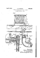
I Figrl s a vertlcalsection through the floor of a house equipped'with, a steamvapor heat- 2 ing plant and illustrating the application of the'present device; r
Fig. ,2 is' a vertical section throughthe air and water. release valve of the present i'nvention as applied to a radiatofland 1 1 Fig. 3 is ajverti'cal sectionthrough the waterfltrap of the present invention as applied to a steam main. p v 7 Referring to the drawings, the floor 4 of a room "supported by suitable floorjoists 5 is illustrated, andsupported on the floor 4 is a supply of steam'to the radiator. In accord-j,
ance with'the present invention, the radiator i steam radiatorfi of standard type. The steam main for a one pipe steam-vapor heating SYS"? v tem,,is' designatedbythe numeral. 7 and is disposed, in accordance with the usual pracq tice, belowthe floor joists 5". A steam supply pipe Srurisupwardly from the main 7 Itothe upper end of the radiator '6,'and a control.
valve 9 is' disposed in the pipe 8to control the 6 at its lower end' is provided with a plu'glO within which a nipple 11 is eccentrically dis-4 posed, the nipple 11 being preferably'situated as close to the'bottom' of the radiator 6 as is conveniently possible. A small vertical drum- 'l2 is secured to the nipple ,llfas' by aunion consistingl of the flangednipple 13' and the draw. nut, 27. The drum 12 runs upwardly from. thefn'ipple .13 "for a short distance and is closed at its upperj end by a removable plug 14.: The drum .may .be'extend'ed fora short I distance below the nipple 13 and closed ad acent its lower end by a web'12a; within which a short vertical tube 15 having a constricted opening therethrough, is, mounted, the tube 15 running downwardly for a short, distance from the web 12a. Secured to the upper end of the tube15 and situated witha in the drum 12, is a small tubular member 16 which extends to a point above the nipple 13 and is closedat its upper end by a cap 17 having a small air opening 17a therein, which aiiords communication between the top portion of thedrum 12 above the nipple 13and the tubular member 16'. 'The tubularmem ber 16 has a bossed opening, 16a disposed downwardly from the top of the member, and a short substantially horizontally disposed tube 18 is secured in the b'ossed opening 16a and runslaterally theretromlthrough the nipples 13 and 11 to the interior ofthe radiator 6. The-radiator endof the tube 18v is slightly,
upwardly inclined, the inclinationthereinbe ing slightly exaggerated for obserVati nQin Fig.2 oi the drawings. The opening in'the tube 18 is preferably of the same size as the opening in-the tube 15, and the tube .18 will afi ord communication-between the radiator;
and the tubular member 16 at apointdiss posed a short distance below the levelot-the air opening 17a in cap 17. I Asshown in'Fig. 2, the drum 12 below the web12a is providedwith a downwardly 6X- tending, internally threaded flange 12b to which adrain pipe 19. is secured. The tube 15 empties into the pipe 19 The. pipe 19 runs downwardly through the floor. 5 and is secured at its lower end to-a Y'-branch fitting 20 disposed a short distance above the main- 7. A short vertical pipe 21 leads downwardly from the fitting 20landis secured'at its lower;
end to a trap. 22 of half U-shape. The trap T 22 is disposedbelow the main 7 and the upper end ofthe trap is connected'to the lower side} of the main by means of a bushing23 and-a nipple 24.1 The pipe 21leads into the lower endof'the trap 22, and preferably a remov able'clean out anddrain plug 25 'isprovided in 'the 'lower end-of the trap. An'inverted U-shaped pipe 26' runs upwardly from the Y-fitting 20 and has its open end disposed a short distance above the main 7 The ordinary steam vapor heating system runs under a normal steam pressure of from one to two ounces per square inch and rare- 1 if ever, runs over a higher pressure than our ounces per square inch. It follows from this that a column of water of comparatively short height can be used to seal an opening in a steam main, such as the main 7, of the steam vapor system above described. Under normal circumstances, when the valve 9 to the radiator 6 is closed and steam under the ordinary pressure used, is supplied through the main 7, water will stand in the radiator 6 at about the level indicated in Fig. 2, and water will fill the trap 22 and the pipe 21 to a short distance above the main 7. The height of the column of water formed in the trap 22, and pipe 21 will, of course, depend on the pressure of steam in the main 7 the pressure formed by the column of water exactly balancing the pressure in the main 7. When the pressure caused by the column of water so formed exceeds the pressure of steam in the main 7, a certain amount of water will flow into the main 7 until an equilibrium is reached. \Vhen the valve 9 is opened, steam will be supplied from the main 7 through the pipe 8 to the radiator 6. Part of this steam will condense to raise the level of the water in the radiator 6 above the radiatorend of the tube 18. There will also be a certain amount of cold, dead air in the radiator 6 which will oppose the steam admitted to the radiator, and prevent the radiator from quickly heating up unless this cold, dead alr is removed. As the water in the radiator rises to a point above the open end of, the tube 18, the water will run through the tube in a substantially horizontal direction and will be discharged into the member 16. The cap 17 on the tubular member 16, will stand above the high level of water in the radiator, the tube 18 being sufficiently large to carry ofl enough water in the radiator to prevent the level thereof ever being suiiiciently high to reach the level of the cap 17 As water drains through the tube 18 into the tubular member 16, this water will run downwardly through the restricted opening in the tube 15 to drain into the pipe 19. As the two tubes 15 and 18 have approximately the same sized openings therethrough and as the tube 18 is horizontally disposed, while the tube 15 is vertically disposed, it will be seen that the water will run downwardly from the tubular member 16 through the tube 15 faster than the water can be supplied to the tubular member 16 from the tube 18. As thewater runs through the tube 15, it, due to its adhesive and cohesive properties, will completely fill the opening in the tube at spaced points, toact like a series of pistons in a cylinder to create a suctionefiect on the air in the tubular member 16. Accordingly, as the water runs downwardly in the tube 15, air will be sucked downwardly with the water, to pull the cold air from the radiator through the nipples 11 and 13, and upper portion of drum 12 downwardly through openin 17a in cap 17 into the tubular member 16.
The excess water and cold air in the radiator 6 will thus be drained ofi and exhausted from the radiator through the tube into the pipe 19. The air so exhausted, will run downwardly through the pipe 19 and fitting 20 and upwardly through the U-shaped pipe 26 to be exhausted therefrom at the air discharge opening therein. As was above stated, when a sufiicient height of water accumulates in the trap 22, fitting 20, and pipes 19 and 26 to over balance by its pressure the pressure of steam in the main 7, part of this water will run into the main 7 until an equilibrium is reached. As steam continues to be supplied to the radiator 6, the water condensing in the bottom of the radiator will be hot water and this water, while it is still bot, will be carried back into the main 7, so that the heat in the water will not be lost. It is found in actual practice that after steam has been applied to the radiator 6 for some time, that the water returned to the main 7 after the steam has condensed in the radiator, will be but a few degrees below the boiling point of water. The present device, accordingly, economizes on the quantity of fuel necessary to run the heating plant.
The tube 18 will be made of such bore that it will always act to carry off suflicient water as the steam condenses in the radiator, so that the lever of water in the radiator can never reach a level corresponding to the height of the u er end of the tubular member 16. Accor ingly, the opening 177; may be considered as being disposed above the high water level of water in the radiator 6, and no drops of water can accumulate on top of the cap 19 to stop up the opening 17a. When the water in the radiator reaches a level below the point where the water will completely fill the bore in the tube 18, both water and air will be carried by the pipe 18 into the tubular member 16. The plug can be removed when necessary to clean out the trap 22 or to drain the main 7 as well as the pipes 19, 26 and 21. Access to the tubular member 16 for cleaning purposes may be readily had by removal of the plug 14 and the cap 17. It will be understood that any number of radiators can be drained into the pipe 19. It will also be understood that a number of traps 22, pipes 21, 26 and 19, may be connected to the main 7 if so desired,
With the present construction, water can be readily drained from the radiator andas the water is drained, a certain amount ofthe coldest air in the radiator will be exhausted from the radiator with thecwater. Accordthe stream into the radiator. The heat of the water drained fromtheradiator will be saved and the present device, therefore, acts as a fuel saver. The parts of the device-are few and the construction is simple. Thedevice is capable of otheruses than in connection with a steam vapor heating system.
Itwill, of course, be understood that various changes may be made in the form, de-
tails, arrangement and proportions, of the various partswithout departing from .the scope of the present invention.
What is claimed is: 1. An air and water release device for use with steam radiators and the like comprising a small drum adapted to be vertically disposed and having a connecting, portion adapted to be connected to the lower end of a radiator to communicate therewith andfhaving an upper portion above said connecting portion, a hollow member disposed in said drum and having an air opening therein above said connecting portion, saidihollow member having a small water drainage opening therein below theupper partof said connecting portion and adapted to communicate with the radiator, said drum being closed at its lower end and atube mounted in said hollow member and running downdrum and having an air opening therein above said connecting portion, a water drainage pipe secured to said member below the upper part of said communicating portion and adapted .to project into the radiator at a pomtpabove the lower part of said communicatmg portion, said drum being closed at its lower end, and a vertical tube closing. c
the lower end of said member and running downwardly therefrom through the closed lower end 'of said drum, said vertical tube having an opening therein of approximately the same size as the opening in said water drainage pipe.
In testimony whereof I affix my si nature.
DANIEL N. STIM ER.
wardly from adjacent the lower end thereof throu h the closed lower end of said drum.
2. in air and waterreleasedevice for use with radiators and the like comprising a small drum adapted to be vertically disposed and having a connecting portion adapted to be connected to the lower end of a radiator to communicate therewith and having an upper portion above said connecting portion,
a'hollo'w memberdisposed in said drum and having an air opening therein above-said connecting portion, atube' adapted to communicate with the interior of a radiator below the level of said air opening in said hollow member and leading to said hollow member below the upper part of said connecting portion, said drum being closed at its lower end and a tube mounted'in said hollow member and runningdownwardly from adfirstomentioned tube at its end connecting with said hollow member being slightly lower than at its end adapted to communicate withthe interior of the radiator.
4. An air and water release device for use r with steam radiators and the like comprising avertical drum having a connecting portion I adapted to be connected to the lower end of a J radiator to communicate therewith and having an upper portion above said connecting portion, a hollow member disposed in said
Priority Applications (1)
| Application Number | Priority Date | Filing Date | Title |
|---|---|---|---|
| US35955729 US1852906A (en) | 1929-05-01 | 1929-05-01 | Pressure and gravity air and water release |
Applications Claiming Priority (1)
| Application Number | Priority Date | Filing Date | Title |
|---|---|---|---|
| US35955729 US1852906A (en) | 1929-05-01 | 1929-05-01 | Pressure and gravity air and water release |
Publications (1)
| Publication Number | Publication Date |
|---|---|
| US1852906A true US1852906A (en) | 1932-04-05 |
Family
ID=23414330
Family Applications (1)
| Application Number | Title | Priority Date | Filing Date |
|---|---|---|---|
| US35955729 Expired - Lifetime US1852906A (en) | 1929-05-01 | 1929-05-01 | Pressure and gravity air and water release |
Country Status (1)
| Country | Link |
|---|---|
| US (1) | US1852906A (en) |
Cited By (1)
| Publication number | Priority date | Publication date | Assignee | Title |
|---|---|---|---|---|
| FR2538093A1 (en) * | 1982-12-17 | 1984-06-22 | Gerbaud Pierre | Method for supplying steam to apparatuses needing such a thermal energy source and installation for implementing such a method |
-
1929
- 1929-05-01 US US35955729 patent/US1852906A/en not_active Expired - Lifetime
Cited By (1)
| Publication number | Priority date | Publication date | Assignee | Title |
|---|---|---|---|---|
| FR2538093A1 (en) * | 1982-12-17 | 1984-06-22 | Gerbaud Pierre | Method for supplying steam to apparatuses needing such a thermal energy source and installation for implementing such a method |
Similar Documents
| Publication | Publication Date | Title |
|---|---|---|
| US1852906A (en) | Pressure and gravity air and water release | |
| US1732505A (en) | Expansion tank | |
| US1636361A (en) | Water heating and deaerating | |
| US1542544A (en) | Separation of air and dissolved gases from liquids | |
| US766281A (en) | Heating system for greenhouses. | |
| RU2125203C1 (en) | Method of dry preservation of heating surfaces of tubes of hot-water boilers at seasonal idle time | |
| US1140896A (en) | Water-heater. | |
| US2049946A (en) | Refrigerating system | |
| US1968834A (en) | Vacuum vapor heating system | |
| US1509810A (en) | Heating system | |
| US1401523A (en) | Heat-exchange system | |
| US1474765A (en) | Steam-heated hot-water radiator | |
| US1237253A (en) | Heating system. | |
| US2692762A (en) | Freeze-proof radiator | |
| US1373072A (en) | Steam-trap fob | |
| GB240938A (en) | Improvements in or relating to central heating apparatus | |
| US1123643A (en) | Siphon-vacuum steam-heating system. | |
| US1514453A (en) | Steam-heating device | |
| GB490528A (en) | Improvements in or relating to steam heating systems | |
| US1386598A (en) | Radiator heating system | |
| US1183853A (en) | Combined high and low pressure vacuum circulating system for heating apparatus. | |
| US1891483A (en) | Automatic evacuator for steam heating systems | |
| US499412A (en) | Major w | |
| US1645132A (en) | Deaerating water | |
| US900233A (en) | Vacuum-generating apparatus for steam-heating systems. |