US1852888A - Gravity controller - Google Patents
Gravity controller Download PDFInfo
- Publication number
- US1852888A US1852888A US432510A US43251030A US1852888A US 1852888 A US1852888 A US 1852888A US 432510 A US432510 A US 432510A US 43251030 A US43251030 A US 43251030A US 1852888 A US1852888 A US 1852888A
- Authority
- US
- United States
- Prior art keywords
- propeller
- pull
- cylinder
- piston
- shaft
- Prior art date
- Legal status (The legal status is an assumption and is not a legal conclusion. Google has not performed a legal analysis and makes no representation as to the accuracy of the status listed.)
- Expired - Lifetime
Links
Images
Classifications
-
- B—PERFORMING OPERATIONS; TRANSPORTING
- B64—AIRCRAFT; AVIATION; COSMONAUTICS
- B64C—AEROPLANES; HELICOPTERS
- B64C29/00—Aircraft capable of landing or taking-off vertically, e.g. vertical take-off and landing [VTOL] aircraft
- B64C29/0008—Aircraft capable of landing or taking-off vertically, e.g. vertical take-off and landing [VTOL] aircraft having its flight directional axis horizontal when grounded
- B64C29/0016—Aircraft capable of landing or taking-off vertically, e.g. vertical take-off and landing [VTOL] aircraft having its flight directional axis horizontal when grounded the lift during taking-off being created by free or ducted propellers or by blowers
- B64C29/0033—Aircraft capable of landing or taking-off vertically, e.g. vertical take-off and landing [VTOL] aircraft having its flight directional axis horizontal when grounded the lift during taking-off being created by free or ducted propellers or by blowers the propellers being tiltable relative to the fuselage
Definitions
- the invention is thecombination of the a rotary motion "of a propeller with an axial movement thereof to increase the efficien cy.
- the object of the invention is to imitate I 5 :with mechanical means, the resultant upward 7 force or reactionof the downward movement of the wings of abird acting on air on the body of the bird which is suspended in the air.
- the object of the invention may also be .de
- the object may also be described as a mechanical device applying the principle of naturalfiight to lift or propel.
- the invention embodies a heavier than air machine capable of securing a strong mid-air vertical liftwhich will also produce a strong pull on land, water, or in the air, or in any direction from the vertical. Therefore, the following is a.
- Figure 1 is a diagrammatical view intending to illustrate the principle of natural flight and'show how, through the law of action and reaction, the small, force of the wings acting through a great space is converted into a great force, the body acting through a small a we space.
- this actionand reaction is rapidly repeated the reaction of the light we1ght of air pulled down through a great space by the wings, add enough to the upward movement of the great force to enable it to over- M come the force of gravity for the time in which this action :and reaction. occurs.
- this principle is followed in the functioning of my invention. It will be noted also that there are two elements n-functioning in the action of a birds wing,
- Figure 2 s a sectional elevationof the machine. It is obvious that it may be mounted; inany suitable manner, upon the object to 'be moved; :In this case the cylinder 1 is mounted on the base 2, and at the head end of; the cylinder isa piston 3 mounted on a shaft 4
- the shaft *4 extendsbeyond the cylinder "head oinabearingfi, and it will be noted that a propeller 'fis mountedto rotate T thereon;
- the shaft 12- is held in a bearing 13 and rotated by the 1110-. tor lei.
- the weighted piston 15 is driven by'one impulseYpercycle,
- a spring 27 is fastened to the upper end of the shaft 4 and coiled around, and fastened to a cylinder 28 which fits over the upper end of the shaft 4 as shown in Fig. 4. This spring floats the weight of the propeller and parts attached to it, upon the second pull or body of the machine. Thus reserving all of the propellers pull for the support of the suction.
- the control of the second pull is obtained by controlling the light pull of the propeller. This is done by exerting a backward pull on the propeller secured from the weight ofsecond pull, causing it to slip any desired amount of its pull, and decrease its eflect onv the second pull proportionally.
- a type of flying machine is illustrated with a plurality of propellers mounted in this manner for raising the machine vertically and driving its horizontally. It will be understood that the propellers may be mounted so that their positions may be adjusted so that they may be used to drive the machine vertically, horizontally or at any angle.
- the cylinder 28 is provided with a head as indicated by the numeral 29, and this cylinder is connected by pipes 30 to compressors 31 operated by eccentrics 32 on the shaft 17, and one of the pipes is provided with a control valve 33 by which the pressure to the cylinder may be controlled.
- a similar valve may be used in the other pipe if desired.
- These pipes form a guard around the propeller blade and as many pipes as desired .may be used, and as they are essentially a.
- Figure 4 is a detail showing the mounting of the upper end of the propeller shaft.
- means for obtaining a resilient connection between a propeller having a rotary motion and a weight having a reciprocatory motion in the axial direction of the propeller said connection enabling the thrust of the propeller to cause the weight to thrust with greater force forward than backward.
- a propeller In a power device, a propeller, a shaft upon which the propeller is mounted, a piston on the end of the shaft opposite to that upon which the propeller is mounted, means for rotatingthe propeller, a cylinder in which the piston is mounted, another piston in the said cylinder, means for reciprocating the said latter piston, and means for causing a,
- a propeller In a propelling device of the character described, a propeller, a reciprocating weight flexibly attached to the said propeller, and means for driving the reciprocating weight with one impulse per cycle.
Landscapes
- Engineering & Computer Science (AREA)
- Aviation & Aerospace Engineering (AREA)
- Toys (AREA)
Description
April 5, 1932. J MASQN 1,852,888
' GRAVITY CONTROLLER Filed March 1, 1950 l INV NT R mlllgm J: Mason ATTORNEY Patented Apr." 5, 1932 i tmme mm P wIL IAivr a. MAsor oF snAr'r E, AS -moron GRAVITY CONTROLLER Application filed March '1,
The invention is thecombination of the a rotary motion "of a propeller with an axial movement thereof to increase the efficien cy.
The object of the invention is to imitate I 5 :with mechanical means, the resultant upward 7 force or reactionof the downward movement of the wings of abird acting on air on the body of the bird which is suspended in the air.
7 The object of the invention may also be .de
10 scribed as amechanical means for converting the light swift pull of an ordinary aerial propeller into a second pull which isslower and proportionally stronger.
1 And the object may also be described as a mechanical device applying the principle of naturalfiight to lift or propel. With these endsin view the invention embodies a heavier than air machine capable of securing a strong mid-air vertical liftwhich will also produce a strong pull on land, water, or in the air, or in any direction from the vertical. Therefore, the following is a.
description of the vertical movement ,only
as this should sufiice for all other directions.
Gravity has little force unless given time to accumulate it, and the functioning of this machine is to allow gravity little or no time to accumulate force.
Other features and advantages of the invention'will appear fromthe following de-' scription taken in connection with the drawings, wherein: I
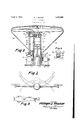
Figure 1 is a diagrammatical view intending to illustrate the principle of natural flight and'show how, through the law of action and reaction, the small, force of the wings acting through a great space is converted into a great force, the body acting through a small a we space. When this actionand reaction is rapidly repeated the reaction of the light we1ght of air pulled down through a great space by the wings, add enough to the upward movement of the great force to enable it to over- M come the force of gravity for the time in which this action :and reaction. occurs. It will be noted that this principle is followed in the functioning of my invention. It will be noted also that there are two elements n-functioning in the action of a birds wing,
namely; the weight of the wing and its spread 1930; erial No. 432,510.
area. :flo facilitate their functioning mechan-x ically they are separated in amanner embody ing an important feature of the invention, which will hereinafter appear. 7
Figure 2s a sectional elevationof the machine. It is obvious that it may be mounted; inany suitable manner, upon the object to 'be moved; :In this case the cylinder 1 is mounted on the base 2, and at the head end of; the cylinder isa piston 3 mounted on a shaft 4 The shaft *4: extendsbeyond the cylinder "head oinabearingfi, and it will be noted that a propeller 'fis mountedto rotate T thereon; Athrust: bearing 8 holds the propeller on the shaft, and apulley 9 is fastened to the propeller, and this is operated by a pulley 10 through a belt 11. The shaft 12- is held in a bearing 13 and rotated by the 1110-. tor lei.
This provides means for rotating the protweenthe pistons 3 and15 is maintained. As;
the propellerlis' rotated it exerts a constant upward pull a little 'grea-ter-than -that of the;- suction, on the weighted -piston l5 by wayof, the. shaft 4 and the piston 3. The weighted piston 15 is driven by'one impulseYpercycle,
delivered toit when it is at or nearthe forward end of its stroke, by a single or two ope posed cylinder two cycle gasolene enginelS, operated with little. or no fly wheel efiect; This intermittent drive allows the suction I to slow the pistons downward movement and; accelerateits upward movement, which causes the upwardthrust of the piston to be as much stronger than its s ,downward I thrust, as the sum of the pull for the time and distance it moved. I It. will lierebe noted that the only 9 liftobtaijned comes fromthe change in' the speed of the weighted piston 15caused by the upward pullfronithe propeller. WVhen these upwardimpulses "are rapidly delivered they j v do not need to hoist or bumptheir load far at" i a time to control gravity. It will be noted that the propeller functions for the spread of the Wing and the weighted piston for the weight of the wing, permitting the beats to be very rapidly repeated mechanically.
A spring 27 is fastened to the upper end of the shaft 4 and coiled around, and fastened to a cylinder 28 which fits over the upper end of the shaft 4 as shown in Fig. 4. This spring floats the weight of the propeller and parts attached to it, upon the second pull or body of the machine. Thus reserving all of the propellers pull for the support of the suction.
The control of the second pull is obtained by controlling the light pull of the propeller. This is done by exerting a backward pull on the propeller secured from the weight ofsecond pull, causing it to slip any desired amount of its pull, and decrease its eflect onv the second pull proportionally.
In the design shown in Figure 3, a type of flying machine is illustrated with a plurality of propellers mounted in this manner for raising the machine vertically and driving its horizontally. It will be understood that the propellers may be mounted so that their positions may be adjusted so that they may be used to drive the machine vertically, horizontally or at any angle.
The cylinder 28 is provided with a head as indicated by the numeral 29, and this cylinder is connected by pipes 30 to compressors 31 operated by eccentrics 32 on the shaft 17, and one of the pipes is provided with a control valve 33 by which the pressure to the cylinder may be controlled. A similar valve may be used in the other pipe if desired. These pipes form a guard around the propeller blade and as many pipes as desired .may be used, and as they are essentially a.
guard and may never be used for compressed air the details of the compressor and cylinder are not shown.
Figure 4 is a detail showing the mounting of the upper end of the propeller shaft.
Having thus fully described the invention, what I claim as new and desire to secure by Letters Patent, is
1. In a propelling device of the character described, means for obtaining a resilient connection between a propeller having a rotary motion and a weight having a reciprocatory motion in the axial direction of the propeller, said connection enabling the thrust of the propeller to cause the weight to thrust with greater force forward than backward.
2. In a power device, a propeller, a shaft upon which the propeller is mounted, a piston on the end of the shaft opposite to that upon which the propeller is mounted, means for rotatingthe propeller, a cylinder in which the piston is mounted, another piston in the said cylinder, means for reciprocating the said latter piston, and means for causing a,
suction in the said cylinder.
3. In a propelling device of the character described, means for obtaining a resilient connection between a propeller having a rotary motion and a weight having a reciprocatory motion in the axial direction of the propeller, and resilient means for floating the weight of the propeller, said connection enabling the thrust of the propeller to cause the weight to thrust with greater force forward than backward and create a second thrust therefrom.
4. In a propelling device of the character described, a propeller, a reciprocating weight flexibly attached to the said propeller, and means for driving the reciprocating weight with one impulse per cycle.
In testimony whereof he aifixes his signature.
WILLIAM J. MASON.
Priority Applications (1)
| Application Number | Priority Date | Filing Date | Title |
|---|---|---|---|
| US432510A US1852888A (en) | 1930-03-01 | 1930-03-01 | Gravity controller |
Applications Claiming Priority (1)
| Application Number | Priority Date | Filing Date | Title |
|---|---|---|---|
| US432510A US1852888A (en) | 1930-03-01 | 1930-03-01 | Gravity controller |
Publications (1)
| Publication Number | Publication Date |
|---|---|
| US1852888A true US1852888A (en) | 1932-04-05 |
Family
ID=23716458
Family Applications (1)
| Application Number | Title | Priority Date | Filing Date |
|---|---|---|---|
| US432510A Expired - Lifetime US1852888A (en) | 1930-03-01 | 1930-03-01 | Gravity controller |
Country Status (1)
| Country | Link |
|---|---|
| US (1) | US1852888A (en) |
-
1930
- 1930-03-01 US US432510A patent/US1852888A/en not_active Expired - Lifetime
Similar Documents
| Publication | Publication Date | Title |
|---|---|---|
| GB2470712A (en) | Air vehicle with flapping rotor | |
| US1852888A (en) | Gravity controller | |
| CN103569360B (en) | Translation flapping wing mechanism and flapping-wing aircraft and the aerodone with translation flapping wing mechanism | |
| US3245637A (en) | Hydraulic driven helicopter group | |
| CN106945834A (en) | Flapping wing with adjustable and self-variable pitch | |
| US3161376A (en) | Ornithopter type aircraft | |
| US3167130A (en) | Reciprocating propeller | |
| US1927535A (en) | Aircraft | |
| CN105539840A (en) | Scheme for simplifying structure of wing flapping machine | |
| US2703147A (en) | Cyclic pitch changing means for helicopters | |
| US2544497A (en) | Multiple flight aircraft | |
| US3162400A (en) | Reciprocating wing helicopter adapted to be manually powered | |
| CN217533266U (en) | a combined drone | |
| US2086883A (en) | Ornigyro | |
| RU2009072C1 (en) | Airship | |
| US1273267A (en) | Flying-machine. | |
| US1735662A (en) | Miniature aeroplane | |
| US3395760A (en) | Aerodynamically feathered helicopter rotor | |
| US2419780A (en) | Convertible airplane adapted for horizontal, vertical, and hovering flight | |
| US2741320A (en) | Helicopter with jet driven rotor | |
| US1014276A (en) | Air-craft. | |
| US1394816A (en) | Flying-machine | |
| US1810114A (en) | Flying machine | |
| US971358A (en) | Aerial machine. | |
| US291990A (en) | davis |