US1852880A - Thread conducting device for sewing machines - Google Patents
Thread conducting device for sewing machines Download PDFInfo
- Publication number
- US1852880A US1852880A US440587A US44058730A US1852880A US 1852880 A US1852880 A US 1852880A US 440587 A US440587 A US 440587A US 44058730 A US44058730 A US 44058730A US 1852880 A US1852880 A US 1852880A
- Authority
- US
- United States
- Prior art keywords
- thread
- bobbin
- sewing machines
- sewing
- conducting device
- Prior art date
- Legal status (The legal status is an assumption and is not a legal conclusion. Google has not performed a legal analysis and makes no representation as to the accuracy of the status listed.)
- Expired - Lifetime
Links
- 238000009958 sewing Methods 0.000 title description 17
- 238000010276 construction Methods 0.000 description 1
- 239000011521 glass Substances 0.000 description 1
- 238000005192 partition Methods 0.000 description 1
Images
Classifications
-
- D—TEXTILES; PAPER
- D05—SEWING; EMBROIDERING; TUFTING
- D05B—SEWING
- D05B91/00—Tools, implements, or accessories for hand sewing
- D05B91/14—Thread-spool pins
Definitions
- This invention relates tothread storing and conducting devices for sewingmachines and more particularly to a thread storing; and conducting device for use in connection with 5 industrial sewing imachines as distinguished fromthose intended primarily for home use, and the invention has asone of its objects to provide a device for this purpose, by which thread may be conducted tothe needle of a sewing machine from a bobbin of'thread so that, where the device is installed upon sewing machines in factories, where clothing and other fabric products are made, a greater quantity of thread may be stored for use than is possible with the ordinary machine employing a bobbin and, furthermore, the time which is ordinarily consumed in winding a bobbin on an ordinary sewingmachine, may be employed in continued sewing.
- Another objectof the invention is to pro-' vide a'thread conducting device for sewing machines, embodying means whereby two bobbins of thread may be stored, ready for the use of thread from either bobbin, so that where it is required to use thread of one color for a period of time and then athread of another color or a .difierent character, this maybe done without removing a bobbin such as the ordinary bobbin, thereby necessitating only a rethreading of the sewing machine needle in order to eii'ect the change in thread;
- Another object of the invention is to provide a device of the class described, which is 'machine needle than where an ordinary smallshuttle and spool of thread are employed as in th'e'case of the ordinary sewing nachine' for household use.
- Figure l is avertical sectional View on theline H of Figure 8, looking in the, di-f rection indicated by the arrows;
- Figure 5 is a'detail viewin front elevation of one of 'the bobbin containers or holders, and illustrating the manner in which; thread may be led in diiferent directions from two bobbin compartments.
- Figure'G is a view in side elevation of the device of Figure 5.
- l I Figure 7 ' is a top plan View thereof.
- Figure 8 is a horizontal sectional view on theline 8 8 of Figure 5.
- l Figure 9r' is a'vertical sectional viewon' the -line-99-of Figure 6.
- Figure 10 is a detail View illustratin one i of the thread conductingv conduits ofthe device.
- a w Figure ll is a vertical transverse sectional view on the-line '1l+11 jof Figure '10, look'- ing inthe' direction indicated bythe arrowsg
- Figure 12 is a similar viewonthe line: 12.12 of Figureli), looking in the direction indicatedby the arrows
- the stands of sewing machines equipped with the invention may be of the standardtype employed in factories and, in practice, the machines may be connected in a row to provide for" simultaneous application of power thereto,and each machine willlinclude;
- a pulley 4 is employed and a belt 5 is trained over this pulley and over another pulley 6 upon a shaft 7 which may be common to two or more of the machines, and which shaft may be operated from a driven shaft 8 by a pulley belt driven as shown in the drawings, and the said shaft 8 driven from any suitable source of power supply, a foot pedal 9 being mounted beneath each machine and constituting means for controlling a clutch 10 so that by exerting pressure upon the pedal, power may be transmitted from the shaft 8 to the pulley l of the machine.
- a casing 11 is mounted beneath the top 1 of the sewing machine and preferably by means securing it to the frame structure which supports the said top, and the top is provided with an opening 12 which is in suostantial registration with an opening 13 formed in the top of the casing.
- the bobbins indicated by the numeral 14 will be arranged within. compartments formed by a partition wall within the casing, and doors 15 will be hinged to the front or side of the casing, and provided with glass panes 16 through which the bobbins of thread may be readily observed, and the quantity of thread remaining readily determined.
- the invention contemplates the direct feeding of the thread from the bobbin to the needle at the lower end of the needle bar 3, and in order that the thread may be conducted with accuracy, a tubular conduit 17 is arranged at one end portion upon the top of the sewing machine, in the embodiment shown in Figures 1 and 2 of the drawings, and with its end in close proximity to the opening 12 in said top, and is then led upwardly as indicated by the numeral 18 beside the pulley 4, and thence horizontally as at 19 above the head of the sewing machine, and to a point vertically in alinement with the needle bar 3, the thread being led from this end of the conduit directly to the needle and bein placed under suitable tension due to the size of the bobbin, and the contact of the thread with the conduit.
- the end of the portion 17 of the conduit is arranged to receive a thread taken from the bobbin in one of the compartments 14 and another conduit, indicated by the numeral 20 will be arranged upon the top of the sewing machine and with one end thereof in uxtaposition to the opening 12 which communicates with the other compartment 14 so that thread may be led through this conduit 20.
- FIG. 3 to 9 inclusive The embodiment of the invention shown in Figures 3 to 9 inclusive is identical with the embodiment shown in Figures 1 and 2 except that the casing 11 for the bobbins is mounted upon the upper side of the top 1 of the sewing machine instead beneath the top.
- the conduit 21 is, in this embodiment, led across the top of the casing, and thence downwardly as indicated by the numeral 20a, and therefore the parts in these figures which correspond to parts in Figures 1 and 2, are indicated by the corresponding reference numerals, primed.
- the conduit through which the thread is led from the bobbin is formed in two sections, one indicated by the numeral 21 and comprising the main section, and a flat section 22, which constitutes a cover or closure section, these sections being hingedly connected as dicated by the numeral 23, and springs b ng arranged upon the pinties 25 of the hi1 23 to yieldably hold the sections 22 in 010 ition, it being understood that by actu is a pring finger latch 26, mounted upon the section 22, and engageable with a keeper 2?, the section 22 may be swung to open posi 'on, against the tension, of the spring to p nit of the thread being led longitudinall ;v the section 21, thus greatly facilitating leading of the thread from the bobbin to the needle bar of the sewing machine.
- a thread conducting ceviee for sewing machines comprising a casing adapted to be supported by the machine, means within the easing for supporting a bobbin of thread, a conduit mounted upon the casing and adapted to lead the thread from the bobbin toward the needle bar of the machine, aid conduit being open at its side and a spring pressed cover section hinged thr ugh the conduitand adapted to close over the open side thereof.
Landscapes
- Engineering & Computer Science (AREA)
- Textile Engineering (AREA)
- Sewing Machines And Sewing (AREA)
Description
April 5, 193% J, v. GONZALEZ THREAD CONDUCTING DEVICE FOR SEWING MACHINES Filed March 51, 1950 NVENTOR 2 Sheets-Sheet l ATTORNEY April 5, 1932.
J. V. GONZALEZ THREAD CONDUCTING DEVICE FOR SEWING MACHINES Filed March 51, 1950 2 Sheets-Sheet 2- Zyalfimuakuz J h vtliit? INVENTOR ATTORNEY Patented Apr.- 5,? .1932
JOSEPH VIDAL GONZALEZ, or MAYAGU Z, Poniro n Ioo THREAD vcoitnuornre navron non SEWING- MACHINES Application filed. March 31,
This invention relates tothread storing and conducting devices for sewingmachines and more particularly to a thread storing; and conducting device for use in connection with 5 industrial sewing imachines as distinguished fromthose intended primarily for home use, and the invention has asone of its objects to provide a device for this purpose, by which thread may be conducted tothe needle of a sewing machine from a bobbin of'thread so that, where the device is installed upon sewing machines in factories, where clothing and other fabric products are made, a greater quantity of thread may be stored for use than is possible with the ordinary machine employing a bobbin and, furthermore, the time which is ordinarily consumed in winding a bobbin on an ordinary sewingmachine, may be employed in continued sewing.
Another objectof the invention is to pro-' vide a'thread conducting device for sewing machines, embodying means whereby two bobbins of thread may be stored, ready for the use of thread from either bobbin, so that where it is required to use thread of one color for a period of time and then athread of another color or a .difierent character, this maybe done without removing a bobbin such as the ordinary bobbin, thereby necessitating only a rethreading of the sewing machine needle in order to eii'ect the change in thread; I
Another object of the invention is to provide a device of the class described, which is 'machine needle than where an ordinary smallshuttle and spool of thread are employed as in th'e'case of the ordinary sewing nachine' for household use. v
This invention also consists in certain other features of construction and in the combination and arrangement of the several parts to be hereinafter fully,describedgillus- I trated .in the accompanying drawings, and
especially designed for industrial or factory 1 use in that it contemplates the provision of 1930. Serial" No. 440,587;
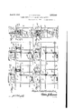
specifically pointed out in the appended claim I v V In describing my inventionin detail,-reference will be had to the accompanying drawings, wherein like characters denote like, or corresponding parts throughout the sev eral views, and in which V Figure l is a View in front elevation illus-. trating two sewing machines connected for operation in unison and equipped with the device of the present invention, and in which embodiment of the invention, the bobbin con-' tainers or housings are concealed from'viewt; Figure 2 is a sectional view on the line 2-2 a of Figure 1, looking in the direction indicated by the arrows; v Figure 3 is a View similar to Figure 1, il lustrating a modified form of the invention in whichthevbobbin containers are located" upon the tops of the machines. I
Figure l is avertical sectional View on theline H of Figure 8, looking in the, di-f rection indicated by the arrows;
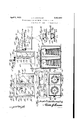
Figure 5 is a'detail viewin front elevation of one of 'the bobbin containers or holders, and illustrating the manner in which; thread may be led in diiferent directions from two bobbin compartments.
Figure'G is a view in side elevation of the device of Figure 5. l I Figure 7 'is a top plan View thereof. Figure 8 is a horizontal sectional view on theline 8 8 of Figure 5. l Figure 9r'is a'vertical sectional viewon' the -line-99-of Figure 6. v v
Figure 10 is a detail View illustratin one i of the thread conductingv conduits ofthe device. a w Figure ll is a vertical transverse sectional view on the-line '1l+11 jofFigure '10, look'- ing inthe' direction indicated bythe arrowsg Figure 12 is a similar viewonthe line: 12.12 of Figureli), looking in the direction indicatedby the arrows The stands of sewing machines equipped with the invention may be of the standardtype employed in factories and, in practice, the machines may be connected in a row to provide for" simultaneous application of power thereto,and each machine willlinclude;
the usual top indicated by the numeral 1 and head 2 in which the needle bar 3 is mounted for vertical reciprocation and, in place of the usual combined hand and fly wheel of the ordinary sewing machine, a pulley 4 is employed and a belt 5 is trained over this pulley and over another pulley 6 upon a shaft 7 which may be common to two or more of the machines, and which shaft may be operated from a driven shaft 8 by a pulley belt driven as shown in the drawings, and the said shaft 8 driven from any suitable source of power supply, a foot pedal 9 being mounted beneath each machine and constituting means for controlling a clutch 10 so that by exerting pressure upon the pedal, power may be transmitted from the shaft 8 to the pulley l of the machine.
The above is of course the usual practice except that the sewing machines usually employed, embody the usual mechanism common to household sewing machines. In the embodiment of the invention shown in Figures 1 and 2 of the drawings, a casing 11 is mounted beneath the top 1 of the sewing machine and preferably by means securing it to the frame structure which supports the said top, and the top is provided with an opening 12 which is in suostantial registration with an opening 13 formed in the top of the casing. Where the casing is to contain two bobbins, the bobbins, indicated by the numeral 14, will be arranged within. compartments formed by a partition wall within the casing, and doors 15 will be hinged to the front or side of the casing, and provided with glass panes 16 through which the bobbins of thread may be readily observed, and the quantity of thread remaining readily determined.
The invention contemplates the direct feeding of the thread from the bobbin to the needle at the lower end of the needle bar 3, and in order that the thread may be conducted with accuracy, a tubular conduit 17 is arranged at one end portion upon the top of the sewing machine, in the embodiment shown in Figures 1 and 2 of the drawings, and with its end in close proximity to the opening 12 in said top, and is then led upwardly as indicated by the numeral 18 beside the pulley 4, and thence horizontally as at 19 above the head of the sewing machine, and to a point vertically in alinement with the needle bar 3, the thread being led from this end of the conduit directly to the needle and bein placed under suitable tension due to the size of the bobbin, and the contact of the thread with the conduit.
The end of the portion 17 of the conduit is arranged to receive a thread taken from the bobbin in one of the compartments 14 and another conduit, indicated by the numeral 20 will be arranged upon the top of the sewing machine and with one end thereof in uxtaposition to the opening 12 which communicates with the other compartment 14 so that thread may be led through this conduit 20.
The embodiment of the invention shown in Figures 3 to 9 inclusive is identical with the embodiment shown in Figures 1 and 2 except that the casing 11 for the bobbins is mounted upon the upper side of the top 1 of the sewing machine instead beneath the top. Likewise, the conduit 21 is, in this embodiment, led across the top of the casing, and thence downwardly as indicated by the numeral 20a, and therefore the parts in these figures which correspond to parts in Figures 1 and 2, are indicated by the corresponding reference numerals, primed.
In this latter embodiment of the invention, as well as in the embodiment shown in Fig ures 1 and 2, the conduit through which the thread is led from the bobbin, is formed in two sections, one indicated by the numeral 21 and comprising the main section, and a flat section 22, which constitutes a cover or closure section, these sections being hingedly connected as dicated by the numeral 23, and springs b ng arranged upon the pinties 25 of the hi1 23 to yieldably hold the sections 22 in 010 ition, it being understood that by actu is a pring finger latch 26, mounted upon the section 22, and engageable with a keeper 2?, the section 22 may be swung to open posi 'on, against the tension, of the spring to p nit of the thread being led longitudinall ;v the section 21, thus greatly facilitating leading of the thread from the bobbin to the needle bar of the sewing machine.
lVhat I claim is A thread conducting ceviee for sewing machines comprising a casing adapted to be supported by the machine, means within the easing for supporting a bobbin of thread, a conduit mounted upon the casing and adapted to lead the thread from the bobbin toward the needle bar of the machine, aid conduit being open at its side and a spring pressed cover section hinged thr ugh the conduitand adapted to close over the open side thereof.
In testimony whereof I ailir: my signature.
JOSEPH VIDAL GONZALEZ.
the
Priority Applications (1)
| Application Number | Priority Date | Filing Date | Title |
|---|---|---|---|
| US440587A US1852880A (en) | 1930-03-31 | 1930-03-31 | Thread conducting device for sewing machines |
Applications Claiming Priority (1)
| Application Number | Priority Date | Filing Date | Title |
|---|---|---|---|
| US440587A US1852880A (en) | 1930-03-31 | 1930-03-31 | Thread conducting device for sewing machines |
Publications (1)
| Publication Number | Publication Date |
|---|---|
| US1852880A true US1852880A (en) | 1932-04-05 |
Family
ID=23749355
Family Applications (1)
| Application Number | Title | Priority Date | Filing Date |
|---|---|---|---|
| US440587A Expired - Lifetime US1852880A (en) | 1930-03-31 | 1930-03-31 | Thread conducting device for sewing machines |
Country Status (1)
| Country | Link |
|---|---|
| US (1) | US1852880A (en) |
Cited By (1)
| Publication number | Priority date | Publication date | Assignee | Title |
|---|---|---|---|---|
| US2431917A (en) * | 1944-12-30 | 1947-12-02 | Ind Sewing Machine Service | Thread rack |
-
1930
- 1930-03-31 US US440587A patent/US1852880A/en not_active Expired - Lifetime
Cited By (1)
| Publication number | Priority date | Publication date | Assignee | Title |
|---|---|---|---|---|
| US2431917A (en) * | 1944-12-30 | 1947-12-02 | Ind Sewing Machine Service | Thread rack |
Similar Documents
| Publication | Publication Date | Title |
|---|---|---|
| US1852880A (en) | Thread conducting device for sewing machines | |
| US1387619A (en) | Sewing-machine | |
| GB534006A (en) | Thread-cutting and -nipping device for sewing machines | |
| US3381641A (en) | Zigzag sewing machine thread spool unwinders | |
| US2387369A (en) | Stop motion device for sewing machines | |
| US579614A (en) | Feeding mechanism for quilting-machsnes | |
| US1467473A (en) | Sewing machine | |
| US4070977A (en) | Sewing machine | |
| US1796236A (en) | Looping device | |
| IE33026L (en) | Thread guide for sewing machines | |
| US1295330A (en) | Sewing-machine. | |
| GB527584A (en) | Apparatus relating to jute or the like spinning machines | |
| US1848804A (en) | Sewing | |
| US2546212A (en) | Sewing machine | |
| US1490972A (en) | Thread-controlling mechanism for sewing machines | |
| US2187522A (en) | Wire stitching machine | |
| US1172417A (en) | Attachment for sewing-machines. | |
| US809428A (en) | Wax-pot for sewing-machines. | |
| US947381A (en) | Two-reel sewing-machine. | |
| US2289902A (en) | Presser mechanism for sewing machines | |
| US2062071A (en) | Silk moistener | |
| US1261170A (en) | Sewing-machine. | |
| US1332071A (en) | Automatic stop for sewing-machines | |
| US2178175A (en) | Sewing machine | |
| GB408762A (en) | Improvements relating to thread spool or bobbin holders for embrodiery and like sewing machines |