US1852876A - Grate - Google Patents
Grate Download PDFInfo
- Publication number
- US1852876A US1852876A US380315A US38031529A US1852876A US 1852876 A US1852876 A US 1852876A US 380315 A US380315 A US 380315A US 38031529 A US38031529 A US 38031529A US 1852876 A US1852876 A US 1852876A
- Authority
- US
- United States
- Prior art keywords
- grate
- air
- coal
- plate
- channels
- Prior art date
- Legal status (The legal status is an assumption and is not a legal conclusion. Google has not performed a legal analysis and makes no representation as to the accuracy of the status listed.)
- Expired - Lifetime
Links
- 108091006146 Channels Proteins 0.000 description 44
- 239000003245 coal Substances 0.000 description 29
- 238000002485 combustion reaction Methods 0.000 description 10
- 239000007789 gas Substances 0.000 description 8
- 239000000779 smoke Substances 0.000 description 6
- 239000002184 metal Substances 0.000 description 5
- 230000000630 rising effect Effects 0.000 description 5
- 239000002956 ash Substances 0.000 description 3
- 238000001816 cooling Methods 0.000 description 2
- 102000007469 Actins Human genes 0.000 description 1
- 108010085238 Actins Proteins 0.000 description 1
- 235000002918 Fraxinus excelsior Nutrition 0.000 description 1
- 239000002802 bituminous coal Substances 0.000 description 1
- 239000011449 brick Substances 0.000 description 1
- 239000003818 cinder Substances 0.000 description 1
- 238000006073 displacement reaction Methods 0.000 description 1
- 238000010438 heat treatment Methods 0.000 description 1
- 238000004519 manufacturing process Methods 0.000 description 1
- 230000008520 organization Effects 0.000 description 1
- 238000009877 rendering Methods 0.000 description 1
- 230000000717 retained effect Effects 0.000 description 1
Images
Classifications
-
- F—MECHANICAL ENGINEERING; LIGHTING; HEATING; WEAPONS; BLASTING
- F23—COMBUSTION APPARATUS; COMBUSTION PROCESSES
- F23H—GRATES; CLEANING OR RAKING GRATES
- F23H13/00—Grates not covered by any of groups F23H1/00-F23H11/00
-
- F—MECHANICAL ENGINEERING; LIGHTING; HEATING; WEAPONS; BLASTING
- F23—COMBUSTION APPARATUS; COMBUSTION PROCESSES
- F23H—GRATES; CLEANING OR RAKING GRATES
- F23H2700/00—Grates characterised by special features or applications
- F23H2700/001—Grates specially adapted for steam boilers
Definitions
- This invention rela'tes to a grate and more particularly to a non-shaking Asectional grate for use in industrial heating plants having either forcedv or natural draft although the 55 principles embodying this invention can also be embodied in a shaking grate.
- One of the objects of this invention is to provide av grate of this character-Which ismade up offseveral sections, the sections beifing identical in constructionand dimensions so that the desired ygrate surface can be obtained by, using the number of grate sections desired.
- y f I Y Y l Another purpose is to provide a grate vseclstion in which the air supplied directlyto the burning coalthroughthe grate is heated by passing ,throughy openingsk provided l:in depending Walls forming channels onk the underside of each grate section before strik-K ZD ing and passing through the horizontal grate surface on which the coal is arranged so that this air does notoperate to chill lthe,v
- Afurther object is to provide such aY grate, I
- each ofthe sections of'Which is made hollow and ⁇ formed to provide one orvmore longie tudinal channels on the under side of the grate, the' air fed directly tothe burning 353-3 coal on the topof the grate being admitted through openings or slots provided in each side channel Wall and directed against thel opposite side wall thereof so as to cool the N channel Walls, the air being subsequentlyV w" conducted from ⁇ these channels through theA topV ofl the grate on which the coal is arranged.
- the incoming air first cools the channel-Walls which cooling,y
- Another aim is to provide such a grate ⁇ which is particularly;y adapted for use with 56SV i soft or bituminous coal in which in particular,v each grate section isl provided at one end with means for directing-streams of hot air into the hotfburning gases andy other products of combustion generated bythe. burning coal.
- ⁇ theV unconsumed products of combustion are brought in "contactwith a fresh supply of hot air so as to'consume the same, therebyresulting M in a moreetcient consumption ofthe coal 60" and a greater amount of heat aswell as providing a smoke consumer.
- a further aim is to provide such meansl for supplying fresh hot air to the products of combustion above the coal in which thev air is heated by passing along enclosed chan nels or chambers formed on the under side of the grateso that before the air is discharged into kthe productsv of combustion the airis heated to a ⁇ very high temperature so as to actin the most vrefficient manner.
- a further aim is to provide such means forsupplying a supply of fresh hot air to theproducts of combustion'which are read- 75 ilyy attached or detached to the grate and Will thereby permit the manufacture of grate surfaces for use with lboth hard coal or softv coal, the smoke consumer beingk supplied channelsk which preheat the air and to the ash v pit without clogging the channels and ren dering them inoperative.
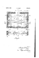
- Figure l is a horizontal section throu rhout a furnace having grate sections embo ying my invention, the grate sections being shown in plan.
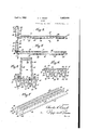
- Figure 2 is a vertical longitudinal section through the furnace taken on line 2 2 of Fig. 1 and showing a side elevation of one of the grate sections.
- Figure 3 is a vertical longitudinal section through one of the grate sections, the same being taken on line 3 3, Fig. 1.
- Figure 4 is a section similar to Fig. 3 taken on line 4 4, Fig. 1.
- Figure 5 is a vertical transverse section through one of the grate sections and the smoke consumer head, the same being taken on line 5 5, Fig. 4.
- Figure 6 is a vertical transverse section through one of the grate sections, the same being taken on line 6 6, Figs. 1 and 3.
- Figure 7 is a perspective view of one of the grate sections, showing the same inverted.
- this invention comprises a plurality of comparatively long and narrow grate sections which are adapted to be placed in a furnace side by side so as to form a continuous horizontal grate surface of any desired size adapted to support a bedv of burning coal, each of said grate sections comprising a comparatively thick cast metal perforated plate, integrally formed comparatively thin walls projecting downwardly from said plate and forming longitudinal channels communicating with the perforations of said plates, a bottom wall enclosing the bottom of each of said channels, end heads enclosing the ends of each channel, said bottom wall being provided with a plurality of longitudinal slots and each of said side walls being provided adjacent its lower end with a plurality of longitudinal slots inclining upwardly to direct the incoming air against the opposite side wall, the perforations in said plate beingr arranged in rows along the center and sides of each channel, a horizontal web connecting the corresponding side walls of adjacent channels, above the openings therein and forming a passage between said channels, end heads enclosing the ends of
- the furnace shown in Figs. 1 and 2 comprises the usual brick walls 10 having an opening 11 at one side through which the coal is stoked onto the grate sections 12.
- These grate sections 12 are arranged side by side and fitted to one another and supported within the furnace on suitable ledges 13 from the walls 10.
- Each ofthe grate sections 12 comprises an elongated horizontal plate 14 which is rectangular in plan and on which the burning coal is supported.
- each of the horizontal plates of each grate section is undercut at one edge as indicated at 15 and is provided with an upper flange 16 at its opposite edge.
- the flanges 16 of each section are fitted into the undercut part 15 of the adjacent section so as to provide an interiitting connection between the grate sections and also provide a mutual support for the grate sections.
- each grate section is formed to provide a plurality of depending channels 17 on the under side of the plate 14, these channels extending substantially the full length of the grate section and being formed by downwardly converging side walls 18 and a bottom wall 19 connecting these side walls.
- Three of such longitudinal channels are shown, but it is apparent that a greater or smaller number can be provided to suit the requirements of the use of the grate section.
- each of these channels 17 air outlet passages lead to the upper surface of the grate plate 14 so as to supply air to the burning coal on top of the grates, these passages comprising central row of openings 20 which extend outwardly from the center of each channel 17 and two rows 21 which extend outwardly from each channel 17 along opposite sides of the central row of openings 20.
- These rows of openings 20 and 21 extend the full length of the grate plates 14 so that air supplied directly to the burning coal on all parts of the grate sections, as best shown in Fig. 1.
- Each of the openings 20 and 21 is also preferably larger at its bottom than at its top so that ashes and cinders falling through the same will not plug but will fall through into the chamber 17.
- Each of the side walls 18 of each channel 17 is provided near its lower end with a series of cold air inlet slots 22, these slots being arranged at an incline, and the bottom wall 19 of each chamber 17 is provided with a series of slots 23.
- Cold air entering the slots 22 from the ash pit passes along the side walls 18 of each channel 17 and thereby operates to cool the side walls of each channel and at the same time heat the air passing through the channel.
- the cooling of the side walls 18 of the chambers operates to cool the grate plate 14 since the side-,'evvallsF182x offith'e channel are e.iformedf/in'e f tegrallyswith thel ⁇ grate.r ⁇ plate wherebyf the heat fro'inf thefrgrate '-.plate..14is .1 conducted:4 11tlfiI-'oughzlth'e metal tozthelsidev Walls of fthe f @channels This'prevents th'egrate surfaces from4 becoming toohot andiresultinginiapos; sible-'burning or l'fusing of :the grate .fplte 14.1? ⁇
- this airoutlet opening 28 being formed inl the plate 14 and leading from, the end of 59 1the passage 25 to theupper surface of the grate.
- inteorally formed re- F taining flanges 29 are provided on the grate 5""-plate 14', these. flanges extending longitudinally of the grate plate and having inwardly projecting overhanging parts 30 which provide a slideway 31'.
- These'slideivays 31 receive outwardly extending flanges 32 pro- *vided on a hollow head 33.. rlhis hollow head is open on its under side and is. formed to provide sidewalls 34., outer and inner Walls 35 and 36 connecting the side Walls and a top Wall 37.
- a 6511horizontal rovv of openings 39 is provided,
- each channel 17 are the Y xeachof thesezopenings preferably beingfdiex rectejddovvnvvardly towardr the burningcoa'l.
- This smoke consumingV device . is .more partic-r ularly suitedffor use with soft coal although it canvr alsoi be used to advantagewith hard coal.' ⁇ its use is, howevergentirely optional and theA outthe hol-lowfheadit
- the heads 33 fare-1 preferably 4in staggered arrangement as indicated in Fig. 1, the heads 33beinagi arranged l at 'opposite endsotthe adjacent sections 12.1
- this invention provides-a grat-eff Which by; reason of its section; form 'can'.:bef-f 3301-* made of substantially any desired size ems f ⁇ ploying the necessarynumber ofsections;
- .A1 grate vbai; comprising. a Iperforated horizontal plate,y Walls depending ⁇ Ifroni 'said-A ⁇ plate v'and iforming pluralityofl channels connnuni'catinglwith .the perforations in'said.:
- said plate hobos provided with an opening for conducting said air from said passage to said hollow head and said hollow head being provided with an opening whereby the air from below said grate is drawn through said passage and head and heated thereby and discharged into the burning gases.
- a grate bar comprising a comparatively thick cast metal horizontal perforated plate, integrally formed comparatively thin walls projecting downwardly from said plate and forming longitudinal channels communicating with the perforations of said plates, a bottom wall for each of said channels, end heads enclosing the ends of each channel, said bottom wall being provided with a plurality of longitudinal slots, each of said side walls being provided adjacent its lower edge with a plurality of longitudinal slots to direct the incoming air against the opposite side wall, the perforations in said plate being arranged in rows along the sides and center of each channel, a horizontal web connecting the corresponding side walls of adjacent channels above the openings therein and forming a passage between said channels, a head enclosing at least one end of said passage, said passage being provided with an opening at one end 'communicating with the air under said grate bar, and a hollow head rising from the opposite end of said plate, said plate being provided with an opening for conducting said air from said passage to said hollow metal head and said hollow head being provided with an opening above said coal
- a grate comprising a grate bar adapted to support a bed of burning coal, spaced parallel horizontal flanges rising from said grate bar and at least one having a laterally extending portion at its upper end and a hollow head adapted to be slid along said grate bar between said flanges and to be retained against displacement by said flanges and said laterally extending portion, said grate bar being provided with an opening admitting air to said hollow head and said hollow head having at least one opening for directing said gir into the burning gases above said grate 4.
- A. grate comprising a grate bar adapted to support a bed of burning coal, spaced parallel horizontal flanges rising from said grate bar and having opposing laterally exnature.
Landscapes
- Engineering & Computer Science (AREA)
- Chemical & Material Sciences (AREA)
- Combustion & Propulsion (AREA)
- Mechanical Engineering (AREA)
- General Engineering & Computer Science (AREA)
- Solid-Fuel Combustion (AREA)
- Incineration Of Waste (AREA)
Description
ilf" 1932v c K. ERNST y 1,852,876
' AGRATEA Filed July 23, 1929 z'sheetS-sheet 1 nos 0000 ODOO o ogn Uso www Zaan/Lut UU QUEUES G UU D DOODOOODOOGODDUOO 9000000 aan Qnaanbonanoa neuuouuoueueuu aucun@ OOOOOODOOOOOOOOOOO OOOOOOOy *n anna anoaoonon nonnen 'euoocvuwcocoomuoucu oqooooooooooooo'o 000000035 QGQGDQQDQQQDQTQQDQQO I r ou., Y= o -P oooo )1 ooo B 9G uw 6" uve ooo oooo non@ non UUUU Dov OOO 000 nu@ nog C. K. ERNST April 5, 1932.
GRATE Filed July 23, 1929 2 Sheets-Sheet 2 PatentedA Apr. 5, 1932.
'y f UNITE cuantas Kok ERNST, F BUFFALO, NEWYORK GRATE.
Apglieanon filed July 23,
This invention'rela'tes to a grate and more particularly to a non-shaking Asectional grate for use in industrial heating plants having either forcedv or natural draft although the 55 principles embodying this invention can also be embodied in a shaking grate.
One of the objects of this invention is to provide av grate of this character-Which ismade up offseveral sections, the sections beifing identical in constructionand dimensions so that the desired ygrate surface can be obtained by, using the number of grate sections desired.y f I Y Y l Another purpose is to provide a grate vseclstion in which the air supplied directlyto the burning coalthroughthe grate is heated by passing ,throughy openingsk provided l:in depending Walls forming channels onk the underside of each grate section before strik-K ZD ing and passing through the horizontal grate surface on which the coal is arranged so that this air does notoperate to chill lthe,v
Y grate surface, Which-chilling Would increase the vproduction of largejolinkers.-v f
2533 Afurther object is to provide such aY grate, I
each ofthe sections of'Which is made hollow and `formed to provide one orvmore longie tudinal channels on the under side of the grate, the' air fed directly tothe burning 353-3 coal on the topof the grate being admitted through openings or slots provided in each side channel Wall and directed against thel opposite side wall thereof so as to cool the N channel Walls, the air being subsequentlyV w" conducted from `these channels through theA topV ofl the grate on which the coal is arranged. By-'this means the incoming air first cools the channel-Walls which cooling,y
L 5g-through'conduction, cools `the grate surface and'preve'nts the grate surface from becoming too hot which would be liable to burn theV grate bar, and at the same time the heatvr from the side Walls ofthe channel operatesto heat the air so that beforepassing through y 1929.k serial No; 380,315.k
the burning coal the air is hot and therefore suited for ,themost `eicient combustion of the coal.` Y
Another aim is to provide such a grate` which is particularly;y adapted for use with 56SV i soft or bituminous coal in which in particular,v each grate section isl provided at one end with means for directing-streams of hot air into the hotfburning gases andy other products of combustion generated bythe. burning coal. Byy this means `theV unconsumed products of combustion are brought in "contactwith a fresh supply of hot air so as to'consume the same, therebyresulting M in a moreetcient consumption ofthe coal 60" and a greater amount of heat aswell as providing a smoke consumer. v
A further aim is to provide such meansl for supplying fresh hot air to the products of combustion above the coal in which thev air is heated by passing along enclosed chan nels or chambers formed on the under side of the grateso that before the air is discharged into kthe productsv of combustion the airis heated to a` very high temperature so as to actin the most vrefficient manner.
A further aim is to provide such means forsupplying a supply of fresh hot air to theproducts of combustion'which are read- 75 ilyy attached or detached to the grate and Will thereby permit the manufacture of grate surfaces for use with lboth hard coal or softv coal, the smoke consumer beingk supplied channelsk which preheat the air and to the ash v pit without clogging the channels and ren dering them inoperative.
In the accompanying drawings:
Figure l is a horizontal section throu rhout a furnace having grate sections embo ying my invention, the grate sections being shown in plan.
Figure 2 is a vertical longitudinal section through the furnace taken on line 2 2 of Fig. 1 and showing a side elevation of one of the grate sections.
Figure 3 is a vertical longitudinal section through one of the grate sections, the same being taken on line 3 3, Fig. 1.
Figure 4 is a section similar to Fig. 3 taken on line 4 4, Fig. 1.
Figure 5 is a vertical transverse section through one of the grate sections and the smoke consumer head, the same being taken on line 5 5, Fig. 4.
Figure 6 is a vertical transverse section through one of the grate sections, the same being taken on line 6 6, Figs. 1 and 3.
Figure 7 is a perspective view of one of the grate sections, showing the same inverted.
In its general organization this invention comprises a plurality of comparatively long and narrow grate sections which are adapted to be placed in a furnace side by side so as to form a continuous horizontal grate surface of any desired size adapted to support a bedv of burning coal, each of said grate sections comprising a comparatively thick cast metal perforated plate, integrally formed comparatively thin walls projecting downwardly from said plate and forming longitudinal channels communicating with the perforations of said plates, a bottom wall enclosing the bottom of each of said channels, end heads enclosing the ends of each channel, said bottom wall being provided with a plurality of longitudinal slots and each of said side walls being provided adjacent its lower end with a plurality of longitudinal slots inclining upwardly to direct the incoming air against the opposite side wall, the perforations in said plate beingr arranged in rows along the center and sides of each channel, a horizontal web connecting the corresponding side walls of adjacent channels, above the openings therein and forming a passage between said channels, end heads enclosing the ends of said passage, said passage being provided with an opening at one end communicating with the air under the grate bar, and a hollow metal head fitted to the opposite end of said plate and rising therefrom said hollow head being open on its underside and said plate being provided with an opening for conducting said air to said hollow head and said hollow head being provided with openings above said coal whereby the air from below said grate is drawn through said passage and head and heated thereby and discharged into the burning gases above said coal.
The furnace shown in Figs. 1 and 2 comprises the usual brick walls 10 having an opening 11 at one side through which the coal is stoked onto the grate sections 12. These grate sections 12 are arranged side by side and fitted to one another and supported within the furnace on suitable ledges 13 from the walls 10. Each ofthe grate sections 12 comprises an elongated horizontal plate 14 which is rectangular in plan and on which the burning coal is supported. To provide an interfitting connection between the edges of the several sections 12 when they are placed in a furnace, each of the horizontal plates of each grate section is undercut at one edge as indicated at 15 and is provided with an upper flange 16 at its opposite edge. By this means the flanges 16 of each section are fitted into the undercut part 15 of the adjacent section so as to provide an interiitting connection between the grate sections and also provide a mutual support for the grate sections.
As best shown in Figs. 3, 6 and 7, each grate section is formed to provide a plurality of depending channels 17 on the under side of the plate 14, these channels extending substantially the full length of the grate section and being formed by downwardly converging side walls 18 and a bottom wall 19 connecting these side walls. Three of such longitudinal channels are shown, but it is apparent that a greater or smaller number can be provided to suit the requirements of the use of the grate section. From each of these channels 17 air outlet passages lead to the upper surface of the grate plate 14 so as to supply air to the burning coal on top of the grates, these passages comprising central row of openings 20 which extend outwardly from the center of each channel 17 and two rows 21 which extend outwardly from each channel 17 along opposite sides of the central row of openings 20. These rows of openings 20 and 21 extend the full length of the grate plates 14 so that air supplied directly to the burning coal on all parts of the grate sections, as best shown in Fig. 1. Each of the openings 20 and 21 is also preferably larger at its bottom than at its top so that ashes and cinders falling through the same will not plug but will fall through into the chamber 17.
Each of the side walls 18 of each channel 17 is provided near its lower end with a series of cold air inlet slots 22, these slots being arranged at an incline, and the bottom wall 19 of each chamber 17 is provided with a series of slots 23. Cold air entering the slots 22 from the ash pit passes along the side walls 18 of each channel 17 and thereby operates to cool the side walls of each channel and at the same time heat the air passing through the channel. The cooling of the side walls 18 of the chambers operates to cool the grate plate 14 since the side-,'evvallsF182x offith'e channel are e.iformedf/in'e f tegrallyswith thel` grate.r` plate wherebyf the heat fro'inf thefrgrate '-.plate..14is .1 conducted:4 11tlfiI-'oughzlth'e metal tozthelsidev Walls of fthe f @channels This'prevents th'egrate surfaces from4 becoming toohot andiresultinginiapos; sible-'burning or l'fusing of :the grate .fplte 14.1?`
r off being-1 heated through contact-.f With-'f the' mfsid-.walls 181 of fthefpreheatingl channels is f heated before it 2 'strikes thefgrate-plate- `14 f and itherefore does notf chill the grate yplate 14.r Such chilling Would result in the forma-4v u tion` oat lrge'clinkersg The preheatedV air "iffrom: the channels 17 thereupon passes up through the openings 2O and 21in the grate plate 14 and enters the burning mass of coal in a heated condition thereby providing :tor the most efficient combustion of 'the coal. Since the openings 20 and 21 are spaced over the entirel surface of each grate plate 14, the fresh air isl supplied uniformly throughout and further provides for eiiicient consumption of the coal.
aos
22 .in the side Walls of the channels 17 andk being formed integrally With the channel muvvalls and the grate plate 14a The passage 25 formed by this web 24 is closed at its ends by integrally formed end heads 26 Which also enclose the ends of the channels 17,` and wat one end an air inlet 27 opening to the 4 i passage 25 is provided in the web 24. At the opposite end of the grate section an air outlet ope-ning 28 is provided for the passage 25,
y this airoutlet opening 28 being formed inl the plate 14 and leading from, the end of 59 1the passage 25 to theupper surface of the grate. At the end of the grate section having air outlet openings 28, inteorally formed re- F taining flanges 29 are provided on the grate 5""-plate 14', these. flanges extending longitudinally of the grate plate and having inwardly projecting overhanging parts 30 which provide a slideway 31'. These'slideivays 31 receive outwardly extending flanges 32 pro- *vided on a hollow head 33.. rlhis hollow head is open on its under side and is. formed to provide sidewalls 34., outer and inner Walls 35 and 36 connecting the side Walls and a top Wall 37. At the top of the inner Wall 36 a 6511horizontal rovv of openings 39 is provided,
Thek slots y23 inr 20' the bottoml Wall 19.0.1c each channel 17 are the Y xeachof thesezopenings preferably beingfdiex rectejddovvnvvardly towardr the burningcoa'l.
31-ormedbythe retaining kflanges 29'ron the. plate and. when inv position covers the air:
Thishead.33aiseslipped intoftheslideways f 28andinto theihead Thisairis then. discharged through the downwardlyfdirected. ports39 and `intothe hot'gas or products of:
combustion fromthe coal on the plates 14.1: This hot fresh airfinjectedfinto the hot fburningfg'gases operatesfto-'consumef anyA uncons-V suniedgas .or sinokeand thereby provide :foria moreV elicientconsumption of thecoalnasv Well fas .reduce` the smoke from :the furnace.:`
This smoke consumingV device .is .more partic-r ularly suitedffor use with soft coal although it canvr alsoi be used to advantagewith hard coal.'` its use is, howevergentirely optional and theA outthe hol-lowfheadit The heads 33 fare-1 preferably 4in staggered arrangement as indicated in Fig. 1, the heads 33beinagi arranged l at 'opposite endsotthe adjacent sections 12.1
Bythis meansfhotfre-sh'air is drawnintothefAl hot products of combustion from t opposite!I sides of the furnace, thereby securing -uniform consumptionwof the unconsumed-prod-z ucts lof combustiony in Vthe hot gases. A.
Asa Whole this invention provides-a grat-eff Which by; reason of its section; form 'can'.:bef-f 3301-* made of substantially any desired size ems f `ploying the necessarynumber ofsections;
the air fed directly to thelburning coal `is-iied.. uniformly over the Ventire: grate ysurface and is heated .to a high temperature 4before being sowfed so as to provide forthemosteiicient consumption ofthe .coal By the arrangement .otfslots in thesideV Walls-of the hollow channels on theundersidefoi' each grate-plate, thea-irzfed to theburning coalis noti only pre heated but also serves to cool the grate plate Without chilling the same thereby -preventing burningrot thegrates :and also'theforniation of -largeclinkersg the. grate sections will not 1 become clogged Tor-plugged soas tol interfere. with Athe supply; of thefair to be cooled; and--A a simple and effective means are-provided for each gratesection. for forcingstreains of kvpre a heated fresh' air into .thefburninggas from* the `coal thereby f resulting; in' a consulnptionf of the -unconsumed products ot combustion aswell `as :eliminating smoke.u The great sectionis alsoainexpensive tomalreaud Will oper.- ate eiic-ientlyfforv a long period oftimer Without requiringcleaning Aor replacing.
I claim as my invention: f
1. .A1, grate vbai; comprising. a Iperforated horizontal plate,y Walls depending` Ifroni 'said-A` plate v'and iforming pluralityofl channels connnuni'catinglwith .the perforations in'said.:
plate, openings provided in said depending walls for admitting air to said channels, a horizontal web connecting the corresponding walls of adjacent channels and forming a passage between said channels, said passage being provided with an opening at one end communicating with the air under said grate bar, a hollow head rising above said plate,
n said plate heilig provided with an opening for conducting said air from said passage to said hollow head and said hollow head being provided with an opening whereby the air from below said grate is drawn through said passage and head and heated thereby and discharged into the burning gases.
2. A grate bar, comprising a comparatively thick cast metal horizontal perforated plate, integrally formed comparatively thin walls projecting downwardly from said plate and forming longitudinal channels communicating with the perforations of said plates, a bottom wall for each of said channels, end heads enclosing the ends of each channel, said bottom wall being provided with a plurality of longitudinal slots, each of said side walls being provided adjacent its lower edge with a plurality of longitudinal slots to direct the incoming air against the opposite side wall, the perforations in said plate being arranged in rows along the sides and center of each channel, a horizontal web connecting the corresponding side walls of adjacent channels above the openings therein and forming a passage between said channels, a head enclosing at least one end of said passage, said passage being provided with an opening at one end 'communicating with the air under said grate bar, and a hollow head rising from the opposite end of said plate, said plate being provided with an opening for conducting said air from said passage to said hollow metal head and said hollow head being provided with an opening above said coal whereby the air from below said grate is drawn through said passage and head and heated thereby and discharged into the burning gases above said coal.
3. A grate, comprising a grate bar adapted to support a bed of burning coal, spaced parallel horizontal flanges rising from said grate bar and at least one having a laterally extending portion at its upper end and a hollow head adapted to be slid along said grate bar between said flanges and to be retained against displacement by said flanges and said laterally extending portion, said grate bar being provided with an opening admitting air to said hollow head and said hollow head having at least one opening for directing said gir into the burning gases above said grate 4. A. grate, comprising a grate bar adapted to support a bed of burning coal, spaced parallel horizontal flanges rising from said grate bar and having opposing laterally exnature.
CHARLES K. ERNST.
Priority Applications (1)
| Application Number | Priority Date | Filing Date | Title |
|---|---|---|---|
| US380315A US1852876A (en) | 1929-07-23 | 1929-07-23 | Grate |
Applications Claiming Priority (1)
| Application Number | Priority Date | Filing Date | Title |
|---|---|---|---|
| US380315A US1852876A (en) | 1929-07-23 | 1929-07-23 | Grate |
Publications (1)
| Publication Number | Publication Date |
|---|---|
| US1852876A true US1852876A (en) | 1932-04-05 |
Family
ID=23500707
Family Applications (1)
| Application Number | Title | Priority Date | Filing Date |
|---|---|---|---|
| US380315A Expired - Lifetime US1852876A (en) | 1929-07-23 | 1929-07-23 | Grate |
Country Status (1)
| Country | Link |
|---|---|
| US (1) | US1852876A (en) |
-
1929
- 1929-07-23 US US380315A patent/US1852876A/en not_active Expired - Lifetime
Similar Documents
| Publication | Publication Date | Title |
|---|---|---|
| US1852876A (en) | Grate | |
| US1775790A (en) | Grate bar | |
| US1513987A (en) | Automatic stoker | |
| US1974143A (en) | Furnace | |
| US1438190A (en) | Grate for stoker furnaces | |
| US2016869A (en) | Fire grate | |
| US1959117A (en) | Grate construction | |
| US1372034A (en) | Air-heating device for supplying heated air to buildings for curing tobacco | |
| US1523137A (en) | Forced-draft furnace | |
| US1840668A (en) | Sawdust burner | |
| US2569438A (en) | Hollow grate bar assembly | |
| US1884917A (en) | Grate bar | |
| US1955996A (en) | Cooled furnace wall | |
| US1672563A (en) | Chain-grate stoker | |
| SU6656A1 (en) | Steam blower device | |
| US1707963A (en) | Boiler | |
| US1548829A (en) | Furnace | |
| US1617197A (en) | Water-cooled grate | |
| US1439116A (en) | Pitch burner | |
| US1362259A (en) | Furnace | |
| US1548402A (en) | Furnace grate | |
| US1178274A (en) | Forced-feed furnace-grate. | |
| SU401A1 (en) | Oil on the furnace for room furnaces | |
| SU33079A1 (en) | Tunnel oven | |
| US1920817A (en) | Fire box construction |