US1852794A - Valve lifting tool - Google Patents
Valve lifting tool Download PDFInfo
- Publication number
- US1852794A US1852794A US252949A US25294928A US1852794A US 1852794 A US1852794 A US 1852794A US 252949 A US252949 A US 252949A US 25294928 A US25294928 A US 25294928A US 1852794 A US1852794 A US 1852794A
- Authority
- US
- United States
- Prior art keywords
- links
- lifting tool
- pair
- valve lifting
- jaw member
- Prior art date
- Legal status (The legal status is an assumption and is not a legal conclusion. Google has not performed a legal analysis and makes no representation as to the accuracy of the status listed.)
- Expired - Lifetime
Links
Images
Classifications
-
- B—PERFORMING OPERATIONS; TRANSPORTING
- B25—HAND TOOLS; PORTABLE POWER-DRIVEN TOOLS; MANIPULATORS
- B25B—TOOLS OR BENCH DEVICES NOT OTHERWISE PROVIDED FOR, FOR FASTENING, CONNECTING, DISENGAGING, OR HOLDING
- B25B27/00—Hand tools, specially adapted for fitting together or separating parts or objects whether or not involving some deformation, not otherwise provided for
- B25B27/14—Hand tools, specially adapted for fitting together or separating parts or objects whether or not involving some deformation, not otherwise provided for for assembling objects other than by press fit or detaching same
- B25B27/24—Hand tools, specially adapted for fitting together or separating parts or objects whether or not involving some deformation, not otherwise provided for for assembling objects other than by press fit or detaching same mounting or demounting valves
- B25B27/26—Hand tools, specially adapted for fitting together or separating parts or objects whether or not involving some deformation, not otherwise provided for for assembling objects other than by press fit or detaching same mounting or demounting valves compressing the springs
-
- Y—GENERAL TAGGING OF NEW TECHNOLOGICAL DEVELOPMENTS; GENERAL TAGGING OF CROSS-SECTIONAL TECHNOLOGIES SPANNING OVER SEVERAL SECTIONS OF THE IPC; TECHNICAL SUBJECTS COVERED BY FORMER USPC CROSS-REFERENCE ART COLLECTIONS [XRACs] AND DIGESTS
- Y10—TECHNICAL SUBJECTS COVERED BY FORMER USPC
- Y10T—TECHNICAL SUBJECTS COVERED BY FORMER US CLASSIFICATION
- Y10T29/00—Metal working
- Y10T29/53—Means to assemble or disassemble
- Y10T29/53552—Valve applying or removing
- Y10T29/53561—Engine valve spring compressor [only]
- Y10T29/53578—Lever operated
- Y10T29/53587—Plier type
Definitions
- This invention relates to a new and useful improvement in valve lifting tools, one of the objects of the invention being to provide a tool which is simple in its construction and efficient in its use and can be quickly operated.
- Another object of the invention is in providing the lifting tool with improved means for locking the jaws in expanded position.
- a further object of the invention is in pro- .18 viding the lifting or separating means of the jaws of a construction so as to provide an automatic locking means.
- Figure 2 is a plan view of Fig. 1.
- Figure 3 is a transverse vertical section taken approximately on the line III-III of Fig. 1.
- 1 designates the lower jaw member which is made of a single piece of strap metal which is bent at 2 intermediate of its ends so as to provide a pair of forwardly extending legs 3, each leg at its extending end being pair of jaws A.
- a jaw member 5 Disposed upwardly of the jaw member 1 is a jaw member 5 which is made of a single piece of strap metal which is bended intermediate of its ends as designated at 6 so as to provide a pair of forwardly extending arms or legs 7 the free end of each arm being formed into a jaw 8.
- the bended end 6 of the arms 7 is mounted between the legs 3 of the jaw member 1 and is pivoted between said legs by the pivot or rivet 9 and mounted on said pivot between the arms 7 of the jaw member 5 is a bell crank lever 10 having a hand engaging portion 11 formed at one end and a connecting portion 12 formed at its opposite end.
- a relatively long pin 18 Supported transversely in the arms 7 of the jaw member 5 is a relatively long pin 18 and transversely mounted in the legs 8 of the jaw member 1 is a relatively long pin 11 and flattened as designated at 4 so as to provide a mounted on the pin 18 is a pair of depending spaced links 15 having a coil spring 16 locate there between and mounted on the pin 13, and mounted on the pin 14 and extending upwardly therefrom is a pair of spaced links 17 said links 15 and 17 being swingingly secured justing bolt 22.
- the jaw members 1 and 5 are operated to contracted positions as shown'in Fig. 1 in which the jaws A and 8 will be adjacent one another so that they can be engaged against the lower end of the valve spring and the seat thereof and upon engaging and pressing down the end 11 of the bell crank lever 10, the jaws A and 8 will be moved to expanded positions thereby compressing the spring so that the valve can be removed and in which the spring can subsequently be displaced.
- the adjusting bolts 21 and 22 are provided, and in which when respective nuts of said bolts are manipulated in a tightening or loosening direction, the jaws can be drawn together or imoved farther apart byreason-of the jaw members l and 5 being made of a resilient material.
- a valve lifting tool comprising a pair of pivoted together jaw members,a lever mounted on the pivot of said jaw members, toggle links connecting said jaws members,
- a valvelifting tool comprising a'pair of pivoted together jaw members, a bell crank lever mounted'on the pivot of said jaw members, a .-pair of pivoted together links each being-connected to a respective jaw member, and a rod connected'to said lever and the connecting pivot of said links.
- a valve lifting tool comprising a pair of cooperable aw members, each of said jaw members being formed of a piece of-strap -metal which is bent on ltself lntermedi-ate of itsends forming paralleling legs, the bent portion of the upper jaw memberbeing inserted between thelegs of the lower jaw member, a pivot passing through the inserted portion of said upper jaw member and the legs of said lower jaw member for securing said members together, a bell crank lever mounted onsaid pivot between the legs of said upper jaw -member, a pair of connected together links'each being connected to a respective jaw member between then-legs thereof, and a rodconnected to said lever and the connectingpivot of'said links.
Landscapes
- Engineering & Computer Science (AREA)
- Mechanical Engineering (AREA)
- Load-Engaging Elements For Cranes (AREA)
Description
April 5, 1932. o. G. STAR K VALVE LIFTING TOOL Filed Feb. 9, 1928 Patented Apr. 5, 1932 UNITED STATES OTTMAR G. STARK, OF ST. LOUIS, MISSOURI VALVE LIF'IING r001.
Application filed February 9, 1928. Serial No. 252,949.
This invention relates to a new and useful improvement in valve lifting tools, one of the objects of the invention being to provide a tool which is simple in its construction and efficient in its use and can be quickly operated.
Another object of the invention is in providing the lifting tool with improved means for locking the jaws in expanded position.
A further object of the invention is in pro- .18 viding the lifting or separating means of the jaws of a construction so as to provide an automatic locking means.
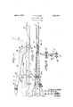
Other and further objects will appear in the specification and be specifically pointed out in the appended claims, reference being had in the accompanying drawings, examplifying the invention, and in which Figure 1 is a side elevation of this improved valve lifting tool in extended position.
Figure 2 is a plan view of Fig. 1.
Figure 3 is a transverse vertical section taken approximately on the line III-III of Fig. 1.
WVith reference to the accompanying drawings, 1 designates the lower jaw member which is made of a single piece of strap metal which is bent at 2 intermediate of its ends so as to provide a pair of forwardly extending legs 3, each leg at its extending end being pair of jaws A.
Disposed upwardly of the jaw member 1 is a jaw member 5 which is made of a single piece of strap metal which is bended intermediate of its ends as designated at 6 so as to provide a pair of forwardly extending arms or legs 7 the free end of each arm being formed into a jaw 8.
The bended end 6 of the arms 7 is mounted between the legs 3 of the jaw member 1 and is pivoted between said legs by the pivot or rivet 9 and mounted on said pivot between the arms 7 of the jaw member 5 is a bell crank lever 10 having a hand engaging portion 11 formed at one end and a connecting portion 12 formed at its opposite end.
Supported transversely in the arms 7 of the jaw member 5 is a relatively long pin 18 and transversely mounted in the legs 8 of the jaw member 1 is a relatively long pin 11 and flattened as designated at 4 so as to provide a mounted on the pin 18 is a pair of depending spaced links 15 having a coil spring 16 locate there between and mounted on the pin 13, and mounted on the pin 14 and extending upwardly therefrom is a pair of spaced links 17 said links 15 and 17 being swingingly secured justing bolt 22.
In the operation of this improved valve lifting tool, the jaw members 1 and 5 are operated to contracted positions as shown'in Fig. 1 in which the jaws A and 8 will be adjacent one another so that they can be engaged against the lower end of the valve spring and the seat thereof and upon engaging and pressing down the end 11 of the bell crank lever 10, the jaws A and 8 will be moved to expanded positions thereby compressing the spring so that the valve can be removed and in which the spring can subsequently be displaced.
In operating the hand engaging portion 11 of the bell crank lever 10 downwardly for swinging the pairs of links 15 and 17 in their vertical positions, this movement of the bell crank lever and the links 15 and 17 expands 35 the jaw members 1 and 5 and the links 15 and 17 when moved to vertical positions will provide an automatic lock for holding the jaw members in the expanded positions. For moving the jaw members to contracted positions, the hand engaging portion 11 is elevated from its abutting position against the bended end 2 of the lower jaw member and swung to the approximate position shown in dotted lines at B in Fig. 1, this elevating movement of the bell crank lever 10 pushing the pivot 18 out of vertical alinement with the pins or pivots 13 or 14 of respective links 15 and 17 and consequently moving said links from locking position.
In order to accommodate the pair of jaws A and the pair of jaws 8 to valve springs of different widths, the adjusting bolts 21 and 22 are provided, and in which when respective nuts of said bolts are manipulated in a tightening or loosening direction, the jaws can be drawn together or imoved farther apart byreason-of the jaw members l and 5 being made of a resilient material.
From the disclosure of this improved valve lifting tool it is obviousfithatvasimp1e,1.eflicient and inexpensive tool is provided and which provides locking means which a're cooperable with the actuating lever and in which said locking means is automatic in'its operation.
What I claim-is:
1. A valve lifting tool comprising a pair of pivoted together jaw members,a lever mounted on the pivot of said jaw members, toggle links connecting said jaws members,
and a rod connecting said lever and the joinmg plvot of said llnks.
2. .A valvelifting tool comprising a'pair of pivoted together jaw members, a bell crank lever mounted'on the pivot of said jaw members, a .-pair of pivoted together links each being-connected to a respective jaw member, and a rod connected'to said lever and the connecting pivot of said links.
3. A valve lifting toolcomprising a pair of cooperable aw members, each of said jaw members being formed of a piece of-strap -metal which is bent on ltself lntermedi-ate of itsends forming paralleling legs, the bent portion of the upper jaw memberbeing inserted between thelegs of the lower jaw member, a pivot passing through the inserted portion of said upper jaw member and the legs of said lower jaw member for securing said members together, a bell crank lever mounted onsaid pivot between the legs of said upper jaw -member, a pair of connected together links'each being connected to a respective jaw member between then-legs thereof, and a rodconnected to said lever and the connectingpivot of'said links.
OTTMAR'G. STAR-K.
Priority Applications (1)
| Application Number | Priority Date | Filing Date | Title |
|---|---|---|---|
| US252949A US1852794A (en) | 1928-02-09 | 1928-02-09 | Valve lifting tool |
Applications Claiming Priority (1)
| Application Number | Priority Date | Filing Date | Title |
|---|---|---|---|
| US252949A US1852794A (en) | 1928-02-09 | 1928-02-09 | Valve lifting tool |
Publications (1)
| Publication Number | Publication Date |
|---|---|
| US1852794A true US1852794A (en) | 1932-04-05 |
Family
ID=22958222
Family Applications (1)
| Application Number | Title | Priority Date | Filing Date |
|---|---|---|---|
| US252949A Expired - Lifetime US1852794A (en) | 1928-02-09 | 1928-02-09 | Valve lifting tool |
Country Status (1)
| Country | Link |
|---|---|
| US (1) | US1852794A (en) |
-
1928
- 1928-02-09 US US252949A patent/US1852794A/en not_active Expired - Lifetime
Similar Documents
| Publication | Publication Date | Title |
|---|---|---|
| US2672778A (en) | Quick-kelease toggle wrench | |
| US1342529A (en) | Spring applier and remover | |
| US1852794A (en) | Valve lifting tool | |
| US2618505A (en) | Lifting clamp | |
| US2341654A (en) | Wrench | |
| US2534985A (en) | Lever and link feed sliding jaw wrench | |
| US2489057A (en) | Lever operated gripping tool with slidable jaw face | |
| US1553623A (en) | Parallel valve-spring lifter | |
| US1734420A (en) | Valve tool | |
| US1651998A (en) | Valve-spring lifter | |
| US2940166A (en) | Valve lifter for diesel motors | |
| US3668765A (en) | Automotive valve spring compressing tools | |
| US1625615A (en) | Pliers | |
| US1814107A (en) | Rail tongs | |
| US1623786A (en) | Automotive tool | |
| US1636058A (en) | Valve lifter | |
| US1588504A (en) | Valve lifter | |
| US1792451A (en) | Valve lifter | |
| US348818A (en) | Pipe and rod vise | |
| US1924246A (en) | Spring compressor | |
| US1608176A (en) | Valve-lifting tool | |
| US1852580A (en) | Tongs for placing keepers on valve stems | |
| US1713762A (en) | Valve-spring compressor | |
| US1540590A (en) | Animal trap | |
| US2006073A (en) | Improved wrench |