US1852740A - Lamp - Google Patents
Lamp Download PDFInfo
- Publication number
- US1852740A US1852740A US387385A US38738529A US1852740A US 1852740 A US1852740 A US 1852740A US 387385 A US387385 A US 387385A US 38738529 A US38738529 A US 38738529A US 1852740 A US1852740 A US 1852740A
- Authority
- US
- United States
- Prior art keywords
- lamp
- shade
- reflector
- socket
- frame
- Prior art date
- Legal status (The legal status is an assumption and is not a legal conclusion. Google has not performed a legal analysis and makes no representation as to the accuracy of the status listed.)
- Expired - Lifetime
Links
Images
Classifications
-
- F—MECHANICAL ENGINEERING; LIGHTING; HEATING; WEAPONS; BLASTING
- F21—LIGHTING
- F21S—NON-PORTABLE LIGHTING DEVICES; SYSTEMS THEREOF; VEHICLE LIGHTING DEVICES SPECIALLY ADAPTED FOR VEHICLE EXTERIORS
- F21S13/00—Non-electric lighting devices or systems employing a point-like light source; Non-electric lighting devices or systems employing a light source of unspecified shape
Definitions
- the present invention relates to lamps and is more particularly directed toward a floor lamp or torchere employing a metal reflector for directing most of the light toward the ceiling and provided with a translucent shade outside the reflector and illuminated at low intensity.
- the present invention contemplates a floor lamp or torchere of the above type so arranged that the translucent covering, such as a parchment shade, may be employed about the metal reflector to conceal the reflector, when not in use, thereby providing a very pleasing appearance.
- the translucent covering such as a parchment shade
- the invention also contemplates placing a reflecting and diffusing medium below the lamp in such a position that it may receive some direct light which is retransmitted onto the inner surface of the translucent parchment or other shade material. This light is diffused by the shade to improve the appearance of the lamp.
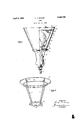
- Figure 1 is a side elevational view with parts in section showing the floor lamp or torchere;
- Figure 2 is an enlarged perspective view showing a form of shade frame which may be employed.
- the lamp is supported on the upper end of a standard indicated by the reference character 10.
- This standard supports a lamp socket 11 in the usual manner and the lamp socket carries a single centrally located lamp bulb 12.
- the lamp socket is covered by a socket housing or cover 13 provided at its upper end with shade holding screws 14. These shade holding screws are adapted to support a shade frame 15 which carries a metallic reflector 16 and av transparent diffusing parchment shade 17.
- his upper ring 24 carries a number of downwardly and inwardly extending members 25 which support a ring 26 of smaller diameter. a The ring 26 is adapted to carry the reflector 16.
- This reflector is generally made out of sheet metal provided with a flange 27 to rest on the ring 26.
- This reflector is open at the bottom as indicated at 28 to permit downwardly directed light to pass through and fall on a shield plate or mirror 29 which may be conveniently made in the form of an aluminum disk. It rests on the ring 20 and is provided with a central hole or aperture ljarlge enough to permit the neck of the lamp When the lamp is in use, the reflector 16 will act on most of the light to direct it upwardly so as to provide strong ceiling illumination.
- the shade material employed may be any of the ordinary types of shade material used in lamp shades. It will be secured to the frame in the manner customarily employed for the material used.
- the reflector 16 and disk 20 are readily removable for lamp renewals and cleaning.
- a lamp comprising a supporting standard, a single centrally located upwardly opening lamp socket, an incandescent lamp in the socket, a socket cover, a shade frame having a lower ring secured to the socket cover, the frame extending upwardly and outwardly therefrom, an aluminum shield plate supported by the lower ring and having a hole to accommodate the neck of the lamp,
- a lamp comprising a supporting standard, a centrally located upwardly opening lamp socket for an incandescent lamp, a socket cover, a shade frame extending upwardly and outwardly therefrom and cooperable with said socket cover, a shield plate supported from the shade frame and having a hole to accommodate the neck of the lamp, an opaque, reflector disposed within the frame and acting to direct nearly all the light flux. upwardly except such as passes through the aperture, the shield plate receiving substantially all the light passing through said aperture and diffusely reflecting it upward outside the reflector, and a diffusing shade disposed outside the reflector alrlid intercepting the light reflected by the s ade.
Description
April 5, 1932.
L. c. DOANE LAMP ' Filed Aug. 21,; 1929 INVENTOR ATTORNEY Patented Apr. 5, 1932 UNITED STATES PATENT OFFICE U'I, ASSIGNOR TO THE MILLER COMPANY,
CORPORATION 01 CONNECTICUT LAM? Application filed August 21,
The present invention relates to lamps and is more particularly directed toward a floor lamp or torchere employing a metal reflector for directing most of the light toward the ceiling and provided with a translucent shade outside the reflector and illuminated at low intensity.
The present invention contemplates a floor lamp or torchere of the above type so arranged that the translucent covering, such as a parchment shade, may be employed about the metal reflector to conceal the reflector, when not in use, thereby providing a very pleasing appearance.
The invention also contemplates placing a reflecting and diffusing medium below the lamp in such a position that it may receive some direct light which is retransmitted onto the inner surface of the translucent parchment or other shade material. This light is diffused by the shade to improve the appearance of the lamp.
The accompanying drawings show, for purposes of illustrating the present invention, one of the many possible embodiments in which the invention may take form, it being understood that the drawings are illustrative of the invention rather than limiting the same.
In the drawings:
Figure 1 is a side elevational view with parts in section showing the floor lamp or torchere; and
Figure 2 is an enlarged perspective view showing a form of shade frame which may be employed.
The lamp is supported on the upper end of a standard indicated by the reference character 10. This standard supports a lamp socket 11 in the usual manner and the lamp socket carries a single centrally located lamp bulb 12. The lamp socket is covered by a socket housing or cover 13 provided at its upper end with shade holding screws 14. These shade holding screws are adapted to support a shade frame 15 which carries a metallic reflector 16 and av transparent diffusing parchment shade 17.
The details of a suitable form of shade frame are shown in Figure 2. Here it is pro- 1929. Serial No. 387,385.
vided with a pair of lower rings 20 and 21 secured together by short spacers 22. These rings are spaced so as to accommodate the screw 14:. Dia-gonally extending uprights or i frame members 23 are carried by the ring 20 65 and these uprights support an upper ring 24.
his upper ring 24: carries a number of downwardly and inwardly extending members 25 which support a ring 26 of smaller diameter. a The ring 26 is adapted to carry the reflector 16.
This reflector is generally made out of sheet metal provided with a flange 27 to rest on the ring 26. This reflector is open at the bottom as indicated at 28 to permit downwardly directed light to pass through and fall on a shield plate or mirror 29 which may be conveniently made in the form of an aluminum disk. It rests on the ring 20 and is provided with a central hole or aperture ljarlge enough to permit the neck of the lamp When the lamp is in use, the reflector 16 will act on most of the light to direct it upwardly so as to provide strong ceiling illumination. A small amount of the light, however, passes down and is reflected and scattered by the shield plate so as to fall on the inside of the translucent screen or shade material 17 thereby illuminating this material, making it glow and bringing out any ornamental design which may be employed. It also renders the entire upper part of the lamp luminous The shade material employed may be any of the ordinary types of shade material used in lamp shades. It will be secured to the frame in the manner customarily employed for the material used. The reflector 16 and disk 20 are readily removable for lamp renewals and cleaning.
What is claimed is:
1. A lamp comprising a supporting standard, a single centrally located upwardly opening lamp socket, an incandescent lamp in the socket, a socket cover, a shade frame having a lower ring secured to the socket cover, the frame extending upwardly and outwardly therefrom, an aluminum shield plate supported by the lower ring and having a hole to accommodate the neck of the lamp,
2. A lamp comprising a supporting standard, a centrally located upwardly opening lamp socket for an incandescent lamp, a socket cover, a shade frame extending upwardly and outwardly therefrom and cooperable with said socket cover, a shield plate supported from the shade frame and having a hole to accommodate the neck of the lamp, an opaque, reflector disposed within the frame and acting to direct nearly all the light flux. upwardly except such as passes through the aperture, the shield plate receiving substantially all the light passing through said aperture and diffusely reflecting it upward outside the reflector, and a diffusing shade disposed outside the reflector alrlid intercepting the light reflected by the s ade.
Signed at Meriden, in the county of New Haven, and State of Connecticut, this 19th day of August, 1929.
LEROY C. DOANE.
Priority Applications (1)
| Application Number | Priority Date | Filing Date | Title |
|---|---|---|---|
| US387385A US1852740A (en) | 1929-08-21 | 1929-08-21 | Lamp |
Applications Claiming Priority (1)
| Application Number | Priority Date | Filing Date | Title |
|---|---|---|---|
| US387385A US1852740A (en) | 1929-08-21 | 1929-08-21 | Lamp |
Publications (1)
| Publication Number | Publication Date |
|---|---|
| US1852740A true US1852740A (en) | 1932-04-05 |
Family
ID=23529637
Family Applications (1)
| Application Number | Title | Priority Date | Filing Date |
|---|---|---|---|
| US387385A Expired - Lifetime US1852740A (en) | 1929-08-21 | 1929-08-21 | Lamp |
Country Status (1)
| Country | Link |
|---|---|
| US (1) | US1852740A (en) |
Cited By (6)
| Publication number | Priority date | Publication date | Assignee | Title |
|---|---|---|---|---|
| US20030015479A1 (en) * | 1999-06-21 | 2003-01-23 | Kuennen Roy W. | Inductively coupled ballast circuit |
| US20030214255A1 (en) * | 1999-06-21 | 2003-11-20 | Baarman David W. | Inductively powered apparatus |
| US20060087282A1 (en) * | 2004-10-27 | 2006-04-27 | Baarman David W | Implement rack and system for energizing implements |
| US20070085487A1 (en) * | 1999-06-21 | 2007-04-19 | Access Business Group International Llc | Inductively Coupled Ballast Circuit |
| US7462951B1 (en) | 2004-08-11 | 2008-12-09 | Access Business Group International Llc | Portable inductive power station |
| US7612528B2 (en) | 1999-06-21 | 2009-11-03 | Access Business Group International Llc | Vehicle interface |
-
1929
- 1929-08-21 US US387385A patent/US1852740A/en not_active Expired - Lifetime
Cited By (27)
| Publication number | Priority date | Publication date | Assignee | Title |
|---|---|---|---|---|
| US7180248B2 (en) | 1999-06-21 | 2007-02-20 | Access Business Group International, Llc | Inductively coupled ballast circuit |
| US8138875B2 (en) | 1999-06-21 | 2012-03-20 | Access Business Group International Llc | Inductively powered apparatus |
| US20030015479A1 (en) * | 1999-06-21 | 2003-01-23 | Kuennen Roy W. | Inductively coupled ballast circuit |
| US20050093475A1 (en) * | 1999-06-21 | 2005-05-05 | Kuennen Roy W. | Inductively coupled ballast circuit |
| US20050122059A1 (en) * | 1999-06-21 | 2005-06-09 | Baarman David W. | Inductively powered apparatus |
| US20050122058A1 (en) * | 1999-06-21 | 2005-06-09 | Baarman David W. | Inductively powered apparatus |
| US20050127849A1 (en) * | 1999-06-21 | 2005-06-16 | Baarman David W. | Inductively powered apparatus |
| US20050127850A1 (en) * | 1999-06-21 | 2005-06-16 | Baarman David W. | Inductively powered apparatus |
| US20070085487A1 (en) * | 1999-06-21 | 2007-04-19 | Access Business Group International Llc | Inductively Coupled Ballast Circuit |
| US7118240B2 (en) | 1999-06-21 | 2006-10-10 | Access Business Group International Llc | Inductively powered apparatus |
| US7126450B2 (en) | 1999-06-21 | 2006-10-24 | Access Business Group International Llc | Inductively powered apparatus |
| US20060284713A1 (en) * | 1999-06-21 | 2006-12-21 | Baarman David W | Inductively powered apparatus |
| US6825620B2 (en) | 1999-06-21 | 2004-11-30 | Access Business Group International Llc | Inductively coupled ballast circuit |
| US20030214255A1 (en) * | 1999-06-21 | 2003-11-20 | Baarman David W. | Inductively powered apparatus |
| US7439684B2 (en) | 1999-06-21 | 2008-10-21 | Access Business Group International Llc | Inductive lamp assembly |
| US7233222B2 (en) | 1999-06-21 | 2007-06-19 | Access Business Group International Llc | Inductively powered apparatus |
| US20070210889A1 (en) * | 1999-06-21 | 2007-09-13 | Access Business Group International Llc | Inductively powered apparatus |
| US7279843B2 (en) | 1999-06-21 | 2007-10-09 | Access Business Group International Llc | Inductively powered apparatus |
| US7385357B2 (en) | 1999-06-21 | 2008-06-10 | Access Business Group International Llc | Inductively coupled ballast circuit |
| US7639110B2 (en) | 1999-06-21 | 2009-12-29 | Access Business Group International Llc | Inductively powered apparatus |
| US7427839B2 (en) | 1999-06-21 | 2008-09-23 | Access Business Group International Llc | Inductively powered apparatus |
| US20070126365A1 (en) * | 1999-06-21 | 2007-06-07 | Baarman David W | Inductively powered apparatus |
| US7615936B2 (en) | 1999-06-21 | 2009-11-10 | Access Business Group International Llc | Inductively powered apparatus |
| US7612528B2 (en) | 1999-06-21 | 2009-11-03 | Access Business Group International Llc | Vehicle interface |
| US7462951B1 (en) | 2004-08-11 | 2008-12-09 | Access Business Group International Llc | Portable inductive power station |
| US7408324B2 (en) | 2004-10-27 | 2008-08-05 | Access Business Group International Llc | Implement rack and system for energizing implements |
| US20060087282A1 (en) * | 2004-10-27 | 2006-04-27 | Baarman David W | Implement rack and system for energizing implements |
Similar Documents
| Publication | Publication Date | Title |
|---|---|---|
| US3037110A (en) | Downlight and device for varying the spectral quality thereof | |
| US1852740A (en) | Lamp | |
| US2185694A (en) | Lighting device | |
| GB499745A (en) | Improvements in electric or other imitation candle or other flame lamps | |
| US2149109A (en) | Lighting fixture | |
| US2066771A (en) | Indirect lighting fixture | |
| US1472050A (en) | Lighting fixture | |
| US1947344A (en) | Reflector | |
| US1818120A (en) | Lighting appliance | |
| US1881594A (en) | Illuminating device | |
| US2255433A (en) | Lamp | |
| US2057263A (en) | Lighting fixture | |
| US2220298A (en) | Luminaire | |
| US2146591A (en) | Portable lamp | |
| US2102462A (en) | Hanger | |
| US1959819A (en) | Lighting fixture | |
| US1998573A (en) | Indirect lighting fixture employing ultraviolet and incandescent lamps | |
| US1945567A (en) | Ultra-violet light luminair | |
| US1777824A (en) | Lighting fixture | |
| US1830263A (en) | Inclosed lighting unit | |
| US1767419A (en) | Lighting fixture | |
| US1824047A (en) | Lamp | |
| US2022264A (en) | Lighting fixture | |
| US1361587A (en) | Reflector | |
| US1962068A (en) | Lighting fixture |