US1852682A - Faucet - Google Patents
Faucet Download PDFInfo
- Publication number
- US1852682A US1852682A US54867131A US1852682A US 1852682 A US1852682 A US 1852682A US 54867131 A US54867131 A US 54867131A US 1852682 A US1852682 A US 1852682A
- Authority
- US
- United States
- Prior art keywords
- casing
- cylindrical member
- outlet openings
- opening
- inlet
- Prior art date
- Legal status (The legal status is an assumption and is not a legal conclusion. Google has not performed a legal analysis and makes no representation as to the accuracy of the status listed.)
- Expired - Lifetime
Links
Images
Classifications
-
- F—MECHANICAL ENGINEERING; LIGHTING; HEATING; WEAPONS; BLASTING
- F16—ENGINEERING ELEMENTS AND UNITS; GENERAL MEASURES FOR PRODUCING AND MAINTAINING EFFECTIVE FUNCTIONING OF MACHINES OR INSTALLATIONS; THERMAL INSULATION IN GENERAL
- F16K—VALVES; TAPS; COCKS; ACTUATING-FLOATS; DEVICES FOR VENTING OR AERATING
- F16K11/00—Multiple-way valves, e.g. mixing valves; Pipe fittings incorporating such valves
- F16K11/02—Multiple-way valves, e.g. mixing valves; Pipe fittings incorporating such valves with all movable sealing faces moving as one unit
- F16K11/04—Multiple-way valves, e.g. mixing valves; Pipe fittings incorporating such valves with all movable sealing faces moving as one unit comprising only lift valves
- F16K11/056—Multiple-way valves, e.g. mixing valves; Pipe fittings incorporating such valves with all movable sealing faces moving as one unit comprising only lift valves with ball-shaped valve members
- F16K11/0565—Multiple-way valves, e.g. mixing valves; Pipe fittings incorporating such valves with all movable sealing faces moving as one unit comprising only lift valves with ball-shaped valve members moving in a combined straight line and rotating movement
-
- Y—GENERAL TAGGING OF NEW TECHNOLOGICAL DEVELOPMENTS; GENERAL TAGGING OF CROSS-SECTIONAL TECHNOLOGIES SPANNING OVER SEVERAL SECTIONS OF THE IPC; TECHNICAL SUBJECTS COVERED BY FORMER USPC CROSS-REFERENCE ART COLLECTIONS [XRACs] AND DIGESTS
- Y10—TECHNICAL SUBJECTS COVERED BY FORMER USPC
- Y10T—TECHNICAL SUBJECTS COVERED BY FORMER US CLASSIFICATION
- Y10T137/00—Fluid handling
- Y10T137/8593—Systems
- Y10T137/86928—Sequentially progressive opening or closing of plural valves
Definitions
- This invention relates to improvements in faucets and, more especially, a double-outlet faucet with a single control or handle.
- a double-outlet faucet with a single control or handle In connection with drinking fountains it is customary toy provide two outlets, one for mouth the self-closing type which is usually desirable in connection with drinking fountains.
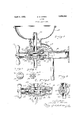
- Figure 1 is a vertical sectional view showing the faucet closed;
- Fig. 2 is a similar view showing the faucet open;
- Fig. 3 is a view ofV one of the cams;
- Fig. 4 is a view of one of the rotatable cylindrical members showing the cam surface thereon; and
- Fig, 5 is a view taken as indicated by the line 5 of Fig. 2.
- the faucet includes a cylindrical casing with an inlet opening l1 in one end and two outlet openings 12 and 13 in its side wall.
- the inlet end of the casingv 10 is here .shown as provided with an extension 14 fastened by means of a union joint 15.
- Numeral 16 may indicate an inlet pipe to which the end of the extension 14 is fastened by the threaded joint 17.
- the outlet opening 12 is Aat the top and the outlet opening 13 at the bot? tom.
- the opening 12 is adapted to receive the lower end of a jet pipe 18 discharging into r the bowl 19 provided with the usual drain pipe 20.
- the opening 13 is litt/ed with a disscribe such means.
- charge pipe 21 adapted for filling receptacles, such as glasses and cups.
- Rotatably mounted in the casing 10i is a cylindrical member 22 having an inlet open.- ing 23 in its inner end, said opening communicating with two outlet openings 24 and 25 in its side wall.
- Means are provided for rotating the cylindrical member 22to cause one of its outlet openings to register with either of the outlet openings 12 or 13 in the' casing..
- the outlet opening 24 registerswith the outlet opening 12 leading to the fountain.
- they outlet 25- ⁇ registers with the outlet 13.
- Such rotation of'l the member 22 is effected by means of the stem 26 attached thereto carryingA the operating handle 27.
- Numeral 28 indicates suitable packing where the stem 26 emerges ⁇ from the casing 10, such packing being located in a suitable cap 29 threaded on the end of the. casingvlO.
- the inlet opening 11 in the casing 10y is controlled by an inlet valve includingthe stationary washer 30 and movable valve seat 321. Means are provided' whereby continued ro-4 tation ofthe handle 27 after bringing one of the openings in the member 22' in registry with one of the outlet openings 121er 13- causes the inlet valve controlling the inletopening 11 to be opened.
- the valve head 3-1 of the inlet valve is carried on the end of a rod 32 extending through the cylindrical member 22.
- the outer end of the cylindrical member 22' as shown in Fig. 4, is provided with two raised cam surfaces having slanting sides 33a, said cam surfaces being separated by fiat portions 34.
- Numeral 35 indi-l cates a ring clamped against the end of the casing 10 by the cap 29, said ring being provided with raised cam' surfaces 36 having slanting sides 37.
- the cam surfaces 36 lie between the raised portions 33T on the end' of the cylindrical member 22'.
- the fiat portions 34 on the end of the' cylinder permit suiiicient rotation to bring one ofi-ts openings into regg?v istry with oneofthe outlet openings 121l or 13 without causing longitudinal movement of the same.
- Continued rotation of the same causes the raised portions 33 to ride upon the raised portions 36, thus causing longitudinal movement of the member 22.
- the adjusting screw 38 may be adjusted to limit the opening of the valve to the desired extent. By screwing it in the lost motion between the head of the screw and the end of the rod 32 will be increased thus limiting the extent of opening of the valve. By screwing the adjusting screw 38 outwardly the valve opening may be increased.
- the end 22aN of the cylindrical member 22 is adapted to engage the end wall l0a of the casu ing l() surrounding the inlet opening 11 te limit the movement of the member 22.
- the cam surfaces and parts are so adjusted that movement of the cylindrical member 22 will be stopped when the outlet ports are in registry.
- the part 22 is shown at the limit of its movement in Fig. 2.
- a faucet of the character described including; a cylindrical casing with an inlet opening in one end and two outlet openings in its side wall; a rotatable cylindrical member in the casing provided with an inlet opening in registry with the inlet opening in the casing, and havingl one or more outlet openings adapted to register with either of the outlet openings in t-.he casing; an inlet valve controlling the inlet opening in the casing; means for rotating the cylindrical member to cause one of its outlet openings to register with either of the outlet openings in the casing; a part connected to the rotating means having a cam surface, another co-operating cam surface adjacent said first-mentioned cam surface, whereby rotation of said rotating means will cause longitudinal movement of said first-mentioned cam surface; and a part on the inlet valve adapted to be engaged by said first-mentioned cam surface in its longitudinal movement to open said inlet valve.
- a faucet of the character described including; a cylindrical casing with an inlet opening in one end and two outlet openings in its side wall; a rotatable cylindrical member in the casing provided with an inlet opening in registry with the inlet opening in the casing and having one or more outlet openings adapted to register with either of the outlet openings in the casing; an inlet valve controlling the inlet opening in the casing; a cam surface on the outer end of the cylindrical member; a co-operating cam surface in the casing; means for rotating the cylindrical member to cause one of its outlet openings to register with either of the outlet openings in the casing, said cam surfaces permitting such rotation of the cylindrical member but so arranged that continued rotation of the same will cause longitudinal movement of said cylindrical member; and a part on the inlet valve adapted to be engaged by longitudinal movement of the cylindrical member to open said inlet valve.
- a faucet of the character described including a cylindrical casing with an inletopening in one end and two outlet openings in its side wall; a cylindrical member rotatably and slidably mounted in the casing, said cylindrical member having an inlet opening in registry with the inlet opening in the casing and one or more outlet openings adapted to register with either of the outlet openings in the casing; an inlet valve controlling the inlet opening in the casing; co-operating cam means on the rotatable cylindrical member and in the casing permitting rotation of the cylindrical member to cause one of its outlet openings to register with either of the outlet openings in the casing, said cam means causing continued rotation of the cylindrical member to slide the same longitudinally in the casing; and means whereby longitudinal sliding of the cylindrical member in the casing causes the inlet valve to open.
Description
April 5, 1932. H, s. STEEN 1,852,682
FAUCET Filed July 5, 1931 Patented Apr. 5, 1932 UNITED STATES PATENT OFFICE HARRY S. STEEN, OF CHICAGO, ILLINOIST ASSIGNOI'Ll TO CHICAGO FAUCET COMPANY,.
F CHICAGO, ILLINOIS, A.. CORPORATION 0F ILLINOIS FAU CET Application led July 3, 1931'. Serial No. 548,671.
This invention relates to improvements in faucets and, more especially, a double-outlet faucet with a single control or handle. In connection with drinking fountains it is customary toy provide two outlets, one for mouth the self-closing type which is usually desirable in connection with drinking fountains.
Although I have shown the faucet of a selfclosing type especially adapted for use with drinking fountains, it is obvious that it may 2(y be made in other forms and adapted to other uses.
Other features and advantages of my in vention will appear more fully as I proceed with my specification.
In that form of device embodying the features of my invention shown in the accompanying drawingsf Figure 1 is a vertical sectional view showing the faucet closed; Fig. 2 is a similar view showing the faucet open; Fig. 3 is a view ofV one of the cams; Fig. 4 is a view of one of the rotatable cylindrical members showing the cam surface thereon; and Fig, 5 is a view taken as indicated by the line 5 of Fig. 2.
As shown in the drawings, the faucet includes a cylindrical casing with an inlet opening l1 in one end and two outlet openings 12 and 13 in its side wall.
The inlet end of the casingv 10 is here .shown as provided with an extension 14 fastened by means of a union joint 15.
As here shown, the outlet opening 12 is Aat the top and the outlet opening 13 at the bot? tom. The opening 12 is adapted to receive the lower end of a jet pipe 18 discharging into r the bowl 19 provided with the usual drain pipe 20. The opening 13 is litt/ed with a disscribe such means.
Rotatably mounted in the casing 10i is a cylindrical member 22 having an inlet open.- ing 23 in its inner end, said opening communicating with two outlet openings 24 and 25 in its side wall. Means are provided for rotating the cylindrical member 22to cause one of its outlet openings to register with either of the outlet openings 12 or 13 in the' casing.. For example, when the member 22 is in the position shown by the solid lines: in Fiig. 5, the outlet opening 24 registerswith the outlet opening 12 leading to the fountain. When it is rotated about 45o to the position shown by the broken lines, they outlet 25-` registers with the outlet 13. Such rotation of'l the member 22 is effected by means of the stem 26 attached thereto carryingA the operating handle 27. Numeral 28 indicates suitable packing where the stem 26 emerges` from the casing 10, such packing being located in a suitable cap 29 threaded on the end of the. casingvlO.
The inlet opening 11 in the casing 10y is controlled by an inlet valve includingthe stationary washer 30 and movable valve seat 321. Means are provided' whereby continued ro-4 tation ofthe handle 27 after bringing one of the openings in the member 22' in registry with one of the outlet openings 121er 13- causes the inlet valve controlling the inletopening 11 to be opened. I shall now de- The valve head 3-1 of the inlet valve is carried on the end of a rod 32 extending through the cylindrical member 22. The outer end of the cylindrical member 22', as shown in Fig. 4, is provided with two raised cam surfaces having slanting sides 33a, said cam surfaces being separated by fiat portions 34. Numeral 35 indi-l cates a ring clamped against the end of the casing 10 by the cap 29, said ring being provided with raised cam' surfaces 36 having slanting sides 37. The cam surfaces 36 lie between the raised portions 33T on the end' of the cylindrical member 22'. The fiat portions 34 on the end of the' cylinder permit suiiicient rotation to bring one ofi-ts openings into regg?v istry with oneofthe outlet openings 121l or 13 without causing longitudinal movement of the same. Continued rotation of the same, however, causes the raised portions 33 to ride upon the raised portions 36, thus causing longitudinal movement of the member 22. This causes the inlet valve to open by causing the head of the adjusting screw 38 to press on the end of the rod 32, thus lifting the head 31 from the washer 30, as shown in Fig. 2. It will be seen that continued rotation of the handle 27 in either direction will thus o en the inlet valve. 'Ihe rod 32 may be provi ed with an extension 32a operating in a restricted opening 39 in the inlet pipe 16. This extension may serve to limit the flow of water. As shown, the inlet valve is adapted to be yieldingly closed by water pressure; and 40 indicates a spiral spring in the cap 29 serving to yieldingly urge the cylindrical member 22 longitudinally to ak position Where it will permit the inlet valve to close.
The adjusting screw 38 may be adjusted to limit the opening of the valve to the desired extent. By screwing it in the lost motion between the head of the screw and the end of the rod 32 will be increased thus limiting the extent of opening of the valve. By screwing the adjusting screw 38 outwardly the valve opening may be increased.
The end 22aN of the cylindrical member 22 is adapted to engage the end wall l0a of the casu ing l() surrounding the inlet opening 11 te limit the movement of the member 22. The cam surfaces and parts are so adjusted that movement of the cylindrical member 22 will be stopped when the outlet ports are in registry. The part 22 is shown at the limit of its movement in Fig. 2.
While I have shown and described certain embodiments of my invention, it is to be understood that it is capable of many modifications. Changes, therefore, in the construction and arrangement may be made without departing from the spirit and scope of the invention as disclosed in the appended claims, in which it is my intention to claim all novelty inherent in my invention as broadly as permissible in view of the prior art.
lVhat I regard as new, and desire to secure by Letters Patent, is:
l. A faucet of the character described, including; a cylindrical casing with an inlet opening in one end and two outlet openings in its side wall; a rotatable cylindrical member in the casing provided with an inlet opening in registry with the inlet opening in the casing, and havingl one or more outlet openings adapted to register with either of the outlet openings in t-.he casing; an inlet valve controlling the inlet opening in the casing; means for rotating the cylindrical member to cause one of its outlet openings to register with either of the outlet openings in the casing; a part connected to the rotating means having a cam surface, another co-operating cam surface adjacent said first-mentioned cam surface, whereby rotation of said rotating means will cause longitudinal movement of said first-mentioned cam surface; and a part on the inlet valve adapted to be engaged by said first-mentioned cam surface in its longitudinal movement to open said inlet valve.
2. A faucet of the character described, including; a cylindrical casing with an inlet opening in one end and two outlet openings in its side wall; a rotatable cylindrical member in the casing provided with an inlet opening in registry with the inlet opening in the casing and having one or more outlet openings adapted to register with either of the outlet openings in the casing; an inlet valve controlling the inlet opening in the casing; a cam surface on the outer end of the cylindrical member; a co-operating cam surface in the casing; means for rotating the cylindrical member to cause one of its outlet openings to register with either of the outlet openings in the casing, said cam surfaces permitting such rotation of the cylindrical member but so arranged that continued rotation of the same will cause longitudinal movement of said cylindrical member; and a part on the inlet valve adapted to be engaged by longitudinal movement of the cylindrical member to open said inlet valve.
3. A faucet of the character described, including a cylindrical casing with an inletopening in one end and two outlet openings in its side wall; a cylindrical member rotatably and slidably mounted in the casing, said cylindrical member having an inlet opening in registry with the inlet opening in the casing and one or more outlet openings adapted to register with either of the outlet openings in the casing; an inlet valve controlling the inlet opening in the casing; co-operating cam means on the rotatable cylindrical member and in the casing permitting rotation of the cylindrical member to cause one of its outlet openings to register with either of the outlet openings in the casing, said cam means causing continued rotation of the cylindrical member to slide the same longitudinally in the casing; and means whereby longitudinal sliding of the cylindrical member in the casing causes the inlet valve to open.
4. A faucet as claimed in claim 3, in which the means for causing the inlet valve to be opened by longitudinal movement of the cylindrical member includes apart on the inlet valve adapted to be engaged by the cylinn drical member in such longitudinal movement..
In witness whereof, I have hereunto set my hand, this 29th day of June, 1931.
HARRY S. STEEN.
Priority Applications (1)
| Application Number | Priority Date | Filing Date | Title |
|---|---|---|---|
| US54867131 US1852682A (en) | 1931-07-03 | 1931-07-03 | Faucet |
Applications Claiming Priority (1)
| Application Number | Priority Date | Filing Date | Title |
|---|---|---|---|
| US54867131 US1852682A (en) | 1931-07-03 | 1931-07-03 | Faucet |
Publications (1)
| Publication Number | Publication Date |
|---|---|
| US1852682A true US1852682A (en) | 1932-04-05 |
Family
ID=24189881
Family Applications (1)
| Application Number | Title | Priority Date | Filing Date |
|---|---|---|---|
| US54867131 Expired - Lifetime US1852682A (en) | 1931-07-03 | 1931-07-03 | Faucet |
Country Status (1)
| Country | Link |
|---|---|
| US (1) | US1852682A (en) |
Cited By (1)
| Publication number | Priority date | Publication date | Assignee | Title |
|---|---|---|---|---|
| US2447207A (en) * | 1940-11-06 | 1948-08-17 | Gen Controls Co | Fluid control valve |
-
1931
- 1931-07-03 US US54867131 patent/US1852682A/en not_active Expired - Lifetime
Cited By (1)
| Publication number | Priority date | Publication date | Assignee | Title |
|---|---|---|---|---|
| US2447207A (en) * | 1940-11-06 | 1948-08-17 | Gen Controls Co | Fluid control valve |
Similar Documents
| Publication | Publication Date | Title |
|---|---|---|
| US20100006164A1 (en) | Bathtub diverter spout with ball valve | |
| US2862520A (en) | Compound valve for mixing, distributing, and volume control of fluid | |
| US2609206A (en) | Mixing faucet | |
| US1016382A (en) | Valve for intermingling and controlling fluids. | |
| US1436650A (en) | Faucet | |
| US1852682A (en) | Faucet | |
| US2398437A (en) | Multiport valve | |
| US2188850A (en) | Valve | |
| US2747603A (en) | Mixing valve | |
| US1742669A (en) | Duplex faucet | |
| US1801847A (en) | Combination hot and cold water faucet | |
| US1894196A (en) | Plug valve | |
| US1607935A (en) | Faucet valve | |
| US1674074A (en) | Irrigating valve | |
| US1122848A (en) | Mixing-valve. | |
| US2015396A (en) | Valve | |
| US1875283A (en) | Combination fatjcet and drinking fountain | |
| US1335946A (en) | Lavatory | |
| US1553447A (en) | Faucet | |
| US1597523A (en) | Multiple intake valve | |
| US1280616A (en) | Graduating bath-valve. | |
| US1746317A (en) | Draft arm for soda fountains | |
| US1694694A (en) | Draft faucet | |
| US2220170A (en) | Valve | |
| US3012582A (en) | Mixing valve |