US1852666A - Carbon holder - Google Patents
Carbon holder Download PDFInfo
- Publication number
- US1852666A US1852666A US487588A US48758830A US1852666A US 1852666 A US1852666 A US 1852666A US 487588 A US487588 A US 487588A US 48758830 A US48758830 A US 48758830A US 1852666 A US1852666 A US 1852666A
- Authority
- US
- United States
- Prior art keywords
- carbon
- carriage
- platen
- plates
- base
- Prior art date
- Legal status (The legal status is an assumption and is not a legal conclusion. Google has not performed a legal analysis and makes no representation as to the accuracy of the status listed.)
- Expired - Lifetime
Links
Images

Classifications
-
- B—PERFORMING OPERATIONS; TRANSPORTING
- B41—PRINTING; LINING MACHINES; TYPEWRITERS; STAMPS
- B41J—TYPEWRITERS; SELECTIVE PRINTING MECHANISMS, i.e. MECHANISMS PRINTING OTHERWISE THAN FROM A FORME; CORRECTION OF TYPOGRAPHICAL ERRORS
- B41J17/00—Mechanisms for manipulating page-width impression-transfer material, e.g. carbon paper
Definitions
- This invention relates particularly to duplicating machines adapted to the purpose of filling in forms on continuous-form stationery.
- the invention is more particularly adapted to a typewriting machine having a shiftable platen carriage and provided with a rearwardly extending frame to support a carbon-holder which is mounted on a rearward extension of the platen carriage.
- the primary object is to provide improved means for supplying continuous strips of carbon between webs of continuous form stationery and particularly stationery of the fan-fold type.
- platen is pivoted to the carriage and is adapt. ed to be swung upward bodily, so that stationery may be conveniently introduced between the platen and the carriage.
- a carbon supply device is removably mounted on an auxiliary carriage, and carbon rolls are mounted on the device with their axes parallel to the path of travel of the paper webs.
- Continuous fanfold stationery may be led over the device and under the platen from the rear.
- Triangular turn plates are supported and positioned alternately on opposite sides of the device so as to interleave the fan.
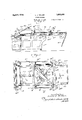
- FIG. 1 is a broken side elevational view of a machine embodying the invention
- Fig. 2 a broken plan View of the same
- Fig. 3 a
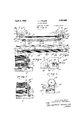
- FIG. 5 is a simllar view taken as indicated at line 5 of Fig. 2; Fig. 6, a broken plan sectional view, taken as indicated at line 6 of Fig. 3; Fig. 7, a vertical sectional view, taken as indicated at line 7 of Fig. 4; Fig. 8, a broken plan view of the auxiliary carriage mounted on the main carriage; Fig. 9, a vertical sectional view taken as indicated at line 9 of Fig. 2; Fig. 10, a sectional detail view of the latch taken as indicated at line 10 of Fig. 9; and .Fig. 11, a broken sectional view of the adjustable stop clamp.
- A designates the main frame of a typewriting machine having a rearward extension A; B, the laterally shiftable carriage carrying the platen B and having a rearward extension B supported by the frame A C an auxiliary carriage mounted on the extension 13 so as to be shiftable longitudinally of the extension and having an operating arm'C and D a carbon-supply device, removably mounted on the auxiliary carriage C.
- the carbon-supply device D is shown as comprising a demountableauxiliary device having a base member 1; carbon rolls 2 and 3 supported at their forward ends by brackets 4 and 5 which are fixedly mounted on the base 1, and at their rearward ends by swinging brackets 6 and 7, pivoted to the base 1 at 6 and 7* respectively; and a series of triangular turn-plates 8 and 9 removably secured to the base member 1.
- the base-member 1 may be constructed of some light sheet metal, preferably aluminum, and is lightened by cutting away large slots. The edge portions of the slots and the plate are shown with downwardly struck flanges 1'7 which serve to strengthen the member.
- a short stud 10 is mounted which extends vertically and is adapted to enter perforations in the turnplates. Openings 11 are provided in the base 1 adjacent the studs 10 and spring slips 12 1 hold themfirmly in position.
- the plates are supported at the corner perforations, provided in the side adjacent the carbon roll, in the manner explained above.
- the plates 8 extend from one side of the device, cantileverwise across the path of paper but do not quite reach the opposite edge of the web.
- the plates 9 project in a similar manner from the opposite side of the device and interleave the plates 8. Spacing lugs 8 and 9 are attached to plates 8 and 9 at the erforations to pro vide a space between ad acent plates for insertion of the carbon strips and paper webs.
- the longer side of the triangle 14 serves as the turning edge.
- Each plate isprovided at its initial apex with an arm or deflector 15, as shown in Fig. 2, which serves to revent the advancing paper web from catc ing and tearing on the turning edges 14 of the plates.
- arm or deflector 15 As the webs are usually provided with transverse lines of weakening, between the sets of forms, thisfeature is of great importance.
- the plates 8 and 9 are similar, the onlydiiference being in that the spacing lugs are attached to opposite sides of the plates.
- the multiple carbon rolls 2 .and 3 from which the carbon strips.2 and 3 are drawn, are removably mounted on square stub shafts 16, which are provided with end plates 16*, and are journaled in the supporting brackets referred to above.
- the stub shafts 16 which are journaled in brackets 4 and 5 are provided with ratchet wheels 17, which may be engaged by pawls 18, as shown in Figs. 4 and 7, to regulate the unwindin of the rolls.
- the pawl is. readily, moved y means of the weighted arm 18 and may be held in the released position by means of a small spring 19.
- Fig. 5 illustrates how the carbon rolls are engaged at their rearward ends by the stub shafts 16 journaled' in the brackets 6 and 7.
- the bracket 7 extends through a perforation provided in the base 1 and is piyoted therefrom at 7..
- a small coil spring 7! is provided to hold the bracket in a vertical position normally but to permit it to be swung backwards when it is desired to replace a carbon roll.
- the auxiliary carriage C as shown in Figs. 8 and 9, is mounted on an extension B which serves as a track for the rollers 21 and permits the carriage to be shifted toward and from the platen. Its rearward travel may be limited by the adjustable clamp 22.
- An operating arm C has a horizontal portion 23 and a forwardly extending handle portion 24.
- the horizontal portion 23 has downwardly offset corner portions 23 which are adapted to be inserted through a slot in the carriage C and be interlocked thereto' by a partial rotation.
- the horizontal portion is also provided with a perforation 23
- the carbon holder pair of depending studs 25 which may be inserted through perforations inthe auxiliary carriage C and be locked thereto by means of latches 26 which are adapted to engage slots in the studs 25. This provision permits installation on standard machines with'out alteration.
- the perforation23 is impaled by one of the studs 25 and the arm is thereby held securely in position.
- Extension arms 27 may be attached to the rear of the member B and a guide-rod 27 provided to guide continuous-form fanfold stationery 28, from a suitable source in rear of the machine, to the carbonsupply device.
- a measuring guide 29 with an adjustable clamp 29, as shown in Figs. 1 and 2 is provided to indicate the length of web which must be drawn forward to include one complete form.
- the machine can be loaded with fan-folded stationery very readily.
- the paper webs may be placed on the machine and the carbon strips inserted alternately from opposite sides of the webs by means of the turn plates 8 and 9. v
- the pawls are released, the platen opened, and the carbon strips and webs drawn forwardly under the platen. down and the webs held thereby in writing position.
- a sufiicient D is provided with a The platen may then be swung length of carbon for theform being used the device is pushed back by means of the arm C" until it isstopped by the clamp 22. This movement will unwind a sufficient length of the carbon strips 2 ⁇ .and 3.
- the ratchet wheels may then be locked by the pawls and the platen will draw the device forwardly by means of the paper webs and carbons.
- the platen may be opened and the paper webs'held by the operator while the carbons are withdrawn by pushing the supply-device back.
- the typed forms may then be drawn out to the guide member 29 and then torn off, which will leave the next set ready for writing.
- a typewriting machine havinga shiftable platen carriage provided with rearwardly extending arms, and a cylindrical platen mounted in said carriage; an auxiliary carriage mounted on said arms for movement toward and from said platen, comprising a plate-likemember provided with slots and perforations, and having rollers mounted on the lower side of said plate-like member adapted to engage and travel on said arms; an operating arm for said auxiliary carriage having a horizontal portion and a forwardly extending handle portion, said horizontal portion being provided with corners oifset downwardly adapted to enter a slot in said auxiliary carriage and to be interlocked thereto by a partial rotation and also being provided with a perforation adapted to register with a perforation in said auxiliary carriage when interlocked thereto; and a carbon supply device mounted on said auxiliary carriage having depending studs adapted to impale said operating arm and project through said perforations in said auxiliary carriage and be locked therein.
- a main frame equipped with a transversely shiftable platen-carriage having a rearward extension; an auxiliary carriage mounted on said extension and movable longitudinally with respect thereto; and a carbon supply device comprising a baseplate demountably supported on said auxillary carriage, a pair of roll-su ports sup ported on said plate near each ateral edge thereof, one support of each pair having mounted thereon a pawl and also having journalled therein a stub-shaft equip with a ratchet wheel co-actin with said pawl, and the other support 0 each pair having journalled therein a stub-shaft, and carbon rolls demountably carried byv said stubshafts.
- a device as specified in claim 2 in which the stub-shafts are provided with angular portions which enga e an lar socketsvwith which the cores of t e car on rolls are provided, one member of each pair of sup orts being pivotally connected with said baseplate and spring-held in operative position.
- sheet-metal base-plate havlng downwardl struck flanges and having depending stud: equipped to be connected with the auxiliary carriage carried by the platen-carriage of the typewriter; a pair of roll-su orts mounted at each lateral margin of saifbase-plate, one
- latching pawl and also having journalled in it a stub-shaft equipped with a ratchet wheel co-acting with said pawl, the other supportof the pair being pivotally mounted and spring-held in operative'po'sition and hav- 2 ing journalled therein a stub-shaft; a pair of carbon rolls demountably carried by said stub-shafts, said rolls being adapted to carry a plurality of carbon strips; turn-plate supports mounted on the upper side of said baseplate adjacent the carbon roll supports; and a plurality of turn-plates demountably carried bysaid last-enumerated supports.
- a carbon supply device comprising a base-plate; means for demountably securing said base-plate upon said auxiliary carriage; and a handle comprising an arm equipped with a plate-like shank adapted to interlockingly engage said auxiliary carriage and be impaled by the means which secure said base-plate to said auxiliary carriage.
- a carbon supply device comprising I a base-plate demountably carried by said auxiliary carriage and equipped with turn-plates and with a pair of roll-supports near each lateral edge of said base-plate, the front support of each pair being equipped with a pawl and also having journalled therein a stubshaft e uipped with a ratchet wheel co-acting with sald pawl and the other support of each pair being pivotally mounted on the baseplate and spring-held in standing position and having journalled therein a stub-shaft; a forwardl extending arm connected with said base-p ate and serving as a handle for the carbon suppl device; and a carbon roll supported on eac pair of stub-shafts.
Description
April 5, 1932. L. J. MILLER CARBON HOLDER Filed Oct. 9, 1950 3 Sheets-Sheet l j/Z 72 i 77: [01:23 J/lieller,
L. J. MILLER CARBON H'OLDER April 5, 1932.
3 Sheets-Sheet 35 Filed Oct. 9, 1930 3 Pl mfl mm .fi. 7
s fm M Q L Patented Apr. 5, 1932 Lo'ors =1.'M1TLLER,.0F cnrcaeo, ILLINOIS, as'srenoia ro UNITED auroenarnro ianers'rnra 00., on onroaeo, ILLINoIs, A oonronarron or ILLINOIS CARBON HOLDER Application filed October 9, 1930; Serial No. 487,588.
This invention relates particularly to duplicating machines adapted to the purpose of filling in forms on continuous-form stationery.
a The invention is more particularly adapted to a typewriting machine having a shiftable platen carriage and provided with a rearwardly extending frame to support a carbon-holder which is mounted on a rearward extension of the platen carriage.
The present invention utilizes certain features disclosed and claimed in my application Serial No. 487,587 filed of even date here with.
The primary object is to provide improved means for supplying continuous strips of carbon between webs of continuous form stationery and particularly stationery of the fan-fold type.
Several of the well known typewritlng machines are provided with a rearwardly extending frame to support an extension of the shiftable platen carriage. An auxiliary carriage is mounted on the extension and is shift- -able in the line of travel of the webs. The
platen is pivoted to the carriage and is adapt. ed to be swung upward bodily, so that stationery may be conveniently introduced between the platen and the carriage.
In accordance with the present invention,
a carbon supply device is removably mounted on an auxiliary carriage, and carbon rolls are mounted on the device with their axes parallel to the path of travel of the paper webs. Continuous fanfold stationery may be led over the device and under the platen from the rear. Triangular turn plates are supported and positioned alternately on opposite sides of the device so as to interleave the fan.-
folded stationery, and carbon strips are drawn fromcarbon rollsand turned by the plates into operative position between the webs of continuous form stationery.
The invention is illustrated in a preferred embodiment in the accompanying drawings in whicha Figure 1 is a broken side elevational view of a machine embodying the invention; Fig. 2, a broken plan View of the same; Fig. 3, a
vertical sectional view taken as indicated at line 3 of Fig. 1; Fig. 3, an enlarged broken sectional View of the webs, strips and plates as viewed in Fig. 3; Fig. 4, a broken vertical sectional view showing a fixed bracket for supporting one end of a carbon roll, taken as indicated at line 4 of Fig. 3; Fig. 5 is a simllar view taken as indicated at line 5 of Fig. 2; Fig. 6, a broken plan sectional view, taken as indicated at line 6 of Fig. 3; Fig. 7, a vertical sectional view, taken as indicated at line 7 of Fig. 4; Fig. 8, a broken plan view of the auxiliary carriage mounted on the main carriage; Fig. 9, a vertical sectional view taken as indicated at line 9 of Fig. 2; Fig. 10, a sectional detail view of the latch taken as indicated at line 10 of Fig. 9; and .Fig. 11, a broken sectional view of the adjustable stop clamp.
Referring to the drawings, A designates the main frame of a typewriting machine having a rearward extension A; B, the laterally shiftable carriage carrying the platen B and having a rearward extension B supported by the frame A C an auxiliary carriage mounted on the extension 13 so as to be shiftable longitudinally of the extension and having an operating arm'C and D a carbon-supply device, removably mounted on the auxiliary carriage C.
The carbon-supply device D is shown as comprising a demountableauxiliary device having a base member 1; carbon rolls 2 and 3 supported at their forward ends by brackets 4 and 5 which are fixedly mounted on the base 1, and at their rearward ends by swinging brackets 6 and 7, pivoted to the base 1 at 6 and 7* respectively; and a series of triangular turn- plates 8 and 9 removably secured to the base member 1. y
The base-member 1 may be constructed of some light sheet metal, preferably aluminum, and is lightened by cutting away large slots. The edge portions of the slots and the plate are shown with downwardly struck flanges 1'7 which serve to strengthen the member.
Near each corner of the base 1 a short stud 10 is mounted which extends vertically and is adapted to enter perforations in the turnplates. Openings 11 are provided in the base 1 adjacent the studs 10 and spring slips 12 1 hold themfirmly in position.
which are pivoted from the lower side of the base at 12, extend through the openings 11 and are adapted to snap over the plates and The turn-plates 8 and 9-consist of thin flat triangular blades, made preferably of a light sheet metal such as aluminum. The plates are supported at the corner perforations, provided in the side adjacent the carbon roll, in the manner explained above. The plates 8 extend from one side of the device, cantileverwise across the path of paper but do not quite reach the opposite edge of the web. The plates 9 project in a similar manner from the opposite side of the device and interleave the plates 8. Spacing lugs 8 and 9 are attached to plates 8 and 9 at the erforations to pro vide a space between ad acent plates for insertion of the carbon strips and paper webs. The longer side of the triangle 14 serves as the turning edge.
Each plate isprovided at its initial apex with an arm or deflector 15, as shown in Fig. 2, which serves to revent the advancing paper web from catc ing and tearing on the turning edges 14 of the plates. As the webs are usually provided with transverse lines of weakening, between the sets of forms, thisfeature is of great importance. 4 The plates 8 and 9 are similar, the onlydiiference being in that the spacing lugs are attached to opposite sides of the plates.
The multiple carbon rolls 2 .and 3 from which the carbon strips.2 and 3 are drawn, are removably mounted on square stub shafts 16, which are provided with end plates 16*, and are journaled in the supporting brackets referred to above. The stub shafts 16 which are journaled in brackets 4 and 5 are provided with ratchet wheels 17, which may be engaged by pawls 18, as shown in Figs. 4 and 7, to regulate the unwindin of the rolls. The pawl is. readily, moved y means of the weighted arm 18 and may be held in the released position by means of a small spring 19.
Fig. 5 illustrates how the carbon rolls are engaged at their rearward ends by the stub shafts 16 journaled' in the brackets 6 and 7. The bracket 7 extends through a perforation provided in the base 1 and is piyoted therefrom at 7.. A small coil spring 7! is provided to hold the bracket in a vertical position normally but to permit it to be swung backwards when it is desired to replace a carbon roll.
The auxiliary carriage C, as shown in Figs. 8 and 9, is mounted on an extension B which serves as a track for the rollers 21 and permits the carriage to be shifted toward and from the platen. Its rearward travel may be limited by the adjustable clamp 22. An operating arm C has a horizontal portion 23 and a forwardly extending handle portion 24. The horizontal portion 23 has downwardly offset corner portions 23 which are adapted to be inserted through a slot in the carriage C and be interlocked thereto' by a partial rotation. The horizontal portion is also provided with a perforation 23 The carbon holder pair of depending studs 25 which may be inserted through perforations inthe auxiliary carriage C and be locked thereto by means of latches 26 which are adapted to engage slots in the studs 25. This provision permits installation on standard machines with'out alteration. The perforation23 is impaled by one of the studs 25 and the arm is thereby held securely in position.
The machine can be loaded with fan-folded stationery very readily. The paper webs may be placed on the machine and the carbon strips inserted alternately from opposite sides of the webs by means of the turn plates 8 and 9. v
After the turn plates have been placed on the proper studs 10 and clamped in position by the spring clips 12 the paper webs, being loaded with carbon, are ready to be drawn forwardly to the platen.
To properly position the carbons, the pawls are released, the platen opened, and the carbon strips and webs drawn forwardly under the platen. down and the webs held thereby in writing position. In order to have just a sufiicient D is provided with a The platen may then be swung length of carbon for theform being used the device is pushed back by means of the arm C" until it isstopped by the clamp 22. This movement will unwind a sufficient length of the carbon strips 2} .and 3. The ratchet wheels may then be locked by the pawls and the platen will draw the device forwardly by means of the paper webs and carbons. When a set of forms has been typed. in, the platen may be opened and the paper webs'held by the operator while the carbons are withdrawn by pushing the supply-device back. The typed forms may then be drawn out to the guide member 29 and then torn off, which will leave the next set ready for writing.
It will be understood that when .the carbons become worn they may be torn off with a set of forms and that by releasing the pawls fresh carbon may be drawn from the rolls as explained above. By adjustment of the clamp 22 the section of the carbon used may be changed and a substantial saving in carbon thereby efi'ected. I
The foregoing detailed description is given be construed as broa 1y as permissible, in,
view of the prior art. 1
What I regard as new, and desire to secure by LettersPatent, is:
1. In combination: a typewriting machine havinga shiftable platen carriage provided with rearwardly extending arms, and a cylindrical platen mounted in said carriage; an auxiliary carriage mounted on said arms for movement toward and from said platen, comprising a plate-likemember provided with slots and perforations, and having rollers mounted on the lower side of said plate-like member adapted to engage and travel on said arms; an operating arm for said auxiliary carriage having a horizontal portion and a forwardly extending handle portion, said horizontal portion being provided with corners oifset downwardly adapted to enter a slot in said auxiliary carriage and to be interlocked thereto by a partial rotation and also being provided with a perforation adapted to register with a perforation in said auxiliary carriage when interlocked thereto; and a carbon supply device mounted on said auxiliary carriage having depending studs adapted to impale said operating arm and project through said perforations in said auxiliary carriage and be locked therein.
2. In combination: a main frame equipped with a transversely shiftable platen-carriage having a rearward extension; an auxiliary carriage mounted on said extension and movable longitudinally with respect thereto; and a carbon supply device comprising a baseplate demountably supported on said auxillary carriage, a pair of roll-su ports sup ported on said plate near each ateral edge thereof, one support of each pair having mounted thereon a pawl and also having journalled therein a stub-shaft equip with a ratchet wheel co-actin with said pawl, and the other support 0 each pair having journalled therein a stub-shaft, and carbon rolls demountably carried byv said stubshafts.
' 3. A device as specified in claim 2 in which the stub-shafts are provided with angular portions which enga e an lar socketsvwith which the cores of t e car on rolls are provided, one member of each pair of sup orts being pivotally connected with said baseplate and spring-held in operative position.
4. In means of the character set forth a carbon supply device comprising a light,
sheet-metal base-plate havlng downwardl struck flanges and having depending stud: equipped to be connected with the auxiliary carriage carried by the platen-carriage of the typewriter; a pair of roll-su orts mounted at each lateral margin of saifbase-plate, one
latching pawl and also having journalled in it a stub-shaft equipped with a ratchet wheel co-acting with said pawl, the other supportof the pair being pivotally mounted and spring-held in operative'po'sition and hav- 2 ing journalled therein a stub-shaft; a pair of carbon rolls demountably carried by said stub-shafts, said rolls being adapted to carry a plurality of carbon strips; turn-plate supports mounted on the upper side of said baseplate adjacent the carbon roll supports; and a plurality of turn-plates demountably carried bysaid last-enumerated supports.
5. In combination with a forwardly and rear'wardly movable auxiliary carriage adapted to be mounted on the platen-carriage of a typewriter: a carbon supply device comprising a base-plate; means for demountably securing said base-plate upon said auxiliary carriage; and a handle comprising an arm equipped with a plate-like shank adapted to interlockingly engage said auxiliary carriage and be impaled by the means which secure said base-plate to said auxiliary carriage.
6. In combination with the auxiliary forwardly and rearwardly shiftable carriage mounted on the platen-carriage of a typewriter; a carbon supply device comprising I a base-plate demountably carried by said auxiliary carriage and equipped with turn-plates and with a pair of roll-supports near each lateral edge of said base-plate, the front support of each pair being equipped with a pawl and also having journalled therein a stubshaft e uipped with a ratchet wheel co-acting with sald pawl and the other support of each pair being pivotally mounted on the baseplate and spring-held in standing position and having journalled therein a stub-shaft; a forwardl extending arm connected with said base-p ate and serving as a handle for the carbon suppl device; and a carbon roll supported on eac pair of stub-shafts.
LOUIS J. MILLER.
support of each pair being equipped with a
Priority Applications (1)
| Application Number | Priority Date | Filing Date | Title |
|---|---|---|---|
| US487588A US1852666A (en) | 1930-10-09 | 1930-10-09 | Carbon holder |
Applications Claiming Priority (1)
| Application Number | Priority Date | Filing Date | Title |
|---|---|---|---|
| US487588A US1852666A (en) | 1930-10-09 | 1930-10-09 | Carbon holder |
Publications (1)
| Publication Number | Publication Date |
|---|---|
| US1852666A true US1852666A (en) | 1932-04-05 |
Family
ID=23936354
Family Applications (1)
| Application Number | Title | Priority Date | Filing Date |
|---|---|---|---|
| US487588A Expired - Lifetime US1852666A (en) | 1930-10-09 | 1930-10-09 | Carbon holder |
Country Status (1)
| Country | Link |
|---|---|
| US (1) | US1852666A (en) |
-
1930
- 1930-10-09 US US487588A patent/US1852666A/en not_active Expired - Lifetime
Similar Documents
| Publication | Publication Date | Title |
|---|---|---|
| US1852666A (en) | Carbon holder | |
| US2563149A (en) | Carbon sheet supporting device | |
| US2075993A (en) | Paper supply controlling attachment for typewriting machines and the like | |
| US1919855A (en) | Carbon supply device for duplicating machines | |
| US1939202A (en) | Record strip control for writing machines | |
| US2109293A (en) | Adapter for typewriters | |
| US1974874A (en) | Duplicating machine | |
| US1386969A (en) | Typewriting-machine | |
| US1995087A (en) | Typewriter attachment | |
| US2082729A (en) | Manifolding device | |
| US1624685A (en) | Manifold-web-printing machine | |
| US2014939A (en) | Receptacle for zigzag folded forms | |
| US1302169A (en) | Type-writing machine. | |
| US964856A (en) | Duplicating device for type-writers. | |
| US1930202A (en) | Web control | |
| US1924048A (en) | Manifolding device for typewriters | |
| US1971202A (en) | Typewriting machine | |
| US1447270A (en) | Typewriting machine | |
| US1876777A (en) | Typewriting machine | |
| US1428265A (en) | Typewriting machine | |
| US1357193A (en) | Typewriting-machine | |
| US1935043A (en) | Record control for billing machines | |
| US1765503A (en) | Typewriting machine | |
| US1821528A (en) | Typewriting machine | |
| US1573424A (en) | Typewriting machine |