US1852644A - Stamping device - Google Patents
Stamping device Download PDFInfo
- Publication number
- US1852644A US1852644A US470897A US47089730A US1852644A US 1852644 A US1852644 A US 1852644A US 470897 A US470897 A US 470897A US 47089730 A US47089730 A US 47089730A US 1852644 A US1852644 A US 1852644A
- Authority
- US
- United States
- Prior art keywords
- casing
- platen
- printing
- plate
- printing plate
- Prior art date
- Legal status (The legal status is an assumption and is not a legal conclusion. Google has not performed a legal analysis and makes no representation as to the accuracy of the status listed.)
- Expired - Lifetime
Links
- 230000033001 locomotion Effects 0.000 description 13
- 230000000717 retained effect Effects 0.000 description 12
- 230000037431 insertion Effects 0.000 description 3
- 238000003780 insertion Methods 0.000 description 3
- 230000008933 bodily movement Effects 0.000 description 2
- 230000006835 compression Effects 0.000 description 2
- 238000007906 compression Methods 0.000 description 2
- 230000000994 depressogenic effect Effects 0.000 description 2
- 230000006872 improvement Effects 0.000 description 2
- 150000001768 cations Chemical class 0.000 description 1
- 230000014759 maintenance of location Effects 0.000 description 1
- 238000004519 manufacturing process Methods 0.000 description 1
- 239000002184 metal Substances 0.000 description 1
- 230000000284 resting effect Effects 0.000 description 1
Images
Classifications
-
- B—PERFORMING OPERATIONS; TRANSPORTING
- B41—PRINTING; LINING MACHINES; TYPEWRITERS; STAMPS
- B41L—APPARATUS OR DEVICES FOR MANIFOLDING, DUPLICATING OR PRINTING FOR OFFICE OR OTHER COMMERCIAL PURPOSES; ADDRESSING MACHINES OR LIKE SERIES-PRINTING MACHINES
- B41L45/00—Kinds or types of addressing machines or of like series-printing machines
- B41L45/02—Kinds or types of addressing machines or of like series-printing machines using printing plates
Definitions
- Thisinvention relates to printing'or stamping devices of the general type exemplified by my copending applications Serial No. 359,816 filed May 2, 1929, and Serial No.
- a device adapted to print perfectly even with rapid or careless operation to provide a device adapted to receive a detachable printing plate of the type carried by customers for identification purposes and adapted for ease of insertion and removal of 29 the printing "plate as in the devices of the above copending application, but which permits a greater and/or more uniform printing pressure to be applied than the devices of the above mentioned applications.
- Another object of the invention is to render the printing pressure and the resulting impression uniform regardless of the speed at which the device is actuated.
- Other objects of the invention are to provide for automatically locking the device in operative position before printing takes place, and further to insure retention of the printing pressure until release thereof by a separate unlocking operation.
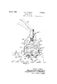
- Fig. 1 is side elevation of a stamping device of the present invention, the side cover of the device being removed, and the device being in position for stamping;
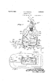
- Fig. 2 is a similar side elevation showing the casing and its contained platen and platen-operating mechanism being swung away from the base preparatory to removal of the printing plate;
- Fig. 3 is a fragmentary section on the line 3-3 of Fig. 1.
- the illustrated stamping device is provided with a backing member 11 serving to oppose the pressure of the printing operation and supported for example by means ofa block 12 above a base 13 at a suflicient height to permit the introduction of a sales book therebetween, with one or more upper leaves of the sales book separated from the remainder of the book and retained abovethe backing member.
- a backing member 11 serving to oppose the pressure of the printing operation and supported for example by means of a block 12 above a base 13 at a suflicient height to permit the introduction of a sales book therebetween, with one or more upper leaves of the sales book separated from the remainder of the book and retained abovethe backing member.
- Suitable provision is made for detachably retaining a printing plate during the printing operation; in the illustrated device this is accomplished by associating with the backing member 11 a raised projecting plate holder 39 which extends within a struck-up recess of a sheet metal printing plate 32 (Fig. 2) carrying on its upper surface raised printing characters which identify the customer.
- This plate holder 39 may, if desired, and as herein illustrated, be mounted with respect to the backing member 11 in the same eneral manner as the plate support disclose in my copending application Serial No. 428,359, for example by the association with the plate holder 39 of two rivets 10 and 41 which extend loosely through openings in the backing member and are forced upwardly by a strong spring which is fastened to the under side of thebackingmember by a screw 51.
- This arrangement of parts is such that the plate holder is yieldingly supported by the spring 50 but is capable of a slight amount of tilting in both dimensions in order successfully to accommodate printing plates having irregularities in height.
- the movable parts of the stamping mechanism are mainly contained within a casing or head 14 which is pivotally mounted with respect to the base 13 by means of a hinge 17
- an inner casing 44 ismounted within the outer casing 14 and has vertical side portions 42 at opposite sides of the casing spaced from the outer casing 14 a slight distance to accommodate an ink ribbon 18 therebetween.
- Suitable ribbon reels 81 and 82 are provided within the casing and an ink ribbon 18 is guided from one of these reels by an adjacent side portion 42 of the inner casing, to the bottom of the casing, then extends across the bottom of the casing in position to overlie a sheet to be printed from the plate 32, and from thence is guided to the opposite ribbon reel by the opposite side portion 42 of the inner casing.
- Suitable mechanism for advancing the ribbon upon each actuation of the operating handle is provided, this mechanism preferably including a tumbler 46 suitably mounted upon the plunger 33 and provided with pawl mechanism adapted to engage ratchet teeth operatively associated with the reels to turn the later, as more fully described in my copending application Serial No. 404,291 filed November 2, 19 29.
- An operating handle 16, fulcr umed to the casing at 16, serves to depress a vertically disposed plunger 33 against the resisting action of a coil spring 34, as indicated in Figs.
- a platen is provided of a size corresponding approximately to the printing surface of the detachable printing plate 32 and capable of a limited vertical movement for pressing the ink ribbon against a sheet of paper superposed on the printing plate.
- the opposite side members 42 of the inner casing are provided-with inwardly curved portions 42 at their lower ends which engage and support the platen 60 at opposite ends when the casing is elevated, as in Fig. 2, the platen having correspondingly curved ends to enga e these supports.
- a perspectiveal bracket 61 extends across the casing and is secured at either end to a vertical side member 42 of the inner casing.
- Pivotally mounted in the bracket 61 are provided two oppositely disposed cam members 52, havin (Fig. 1) relatively long lever arms adapte to abut a flat lower surface 33 of the vertical plunger 33, and having relatively short lever arms terminating in projections 52 and 52 which abut the upper surface of the platen 60.
- the projections 52 of the shorter lever arm of the cam members 52 are so disposed with respect to the cam centers 52 that depression of the plunger 33 and consequent swinging of the cam levers serves to depress the platen 60 and causes the plate to apply printing pressure to the ink ribbon and a sheet of paper resting upon the printing plate.
- mechanism for exerting a strong downward force upon platen 60, by means of the cams 52, this force naturally being accompanied by a force of reaction upon the cams and casing tending to move these parts upward and away from the I sheet or sheets being printed. If unopposed, such movement would tend to interfere with effective application of high printing compression.
- the latch 7 0 may be released to enable the casing 14 to be swung back to the right away from the printing plate and sheet of paper as in Fig. 2.
- the platen 60 ceases to react on the cam levers 52 and 53 and enables the spring 59 to return these cam levers to their uppermost or inactive positions.
- the-bracket 61 preferably serves as a stop for the lunger 33, so that the natural tendency of t .e operator is to depress the operating handle until the plunger strikes this stop.
- a stampin device comprisin a base including a plate older for detacha I retaining a printing plate, a casing mova le with respect to said base, a platen associated with said casing and adapted to cooperate with a printing plate retained by said plate holder, and actuating means for moving said platen to a predetermined pressure-applying osition with respect to said casing and wit rethe pressure applied by the platen.
- a stamping device comprising a plate holder for detachably ret'almng a printing' plate, and a cooperating platen, a casin a plunger in said casing, a pivoted mem er adapted to swing to transmit movement of the plunger to the platen topress the platen toward the printing plate, sa1d pivoted member being movable b sa1d plunger past its maximum point of t row.
- a stamping device comprising a plate holder for etachably retaining a printing plate, a pressure device, a casing for the pressure device pivotally mounted to move away from the plate holder to ex ose the plate holder for the insertion in t e device of a printing plate and a sheet to be stamped and to move into position for the pressure device to react on the printing plate and sheet, and a latch device for retaining the casing in this latter position during the printing operation.
- a stamping device comprising a plate holder for detachably retaining a printing plate, a pressure device including a platen, a cam for actuating the platen and operating means for turning the cam, and a latch for retaining the cam against bodily movement away from the plate holder during operation of the platen by the cam.
- a stamping device comprising a base including means for detachably retaining a printing plate, a casing pivoted to the base, a pressure device within the casing, an operating handle fulcrumed upon the casing for operating the pressure devlce, and a latch for temporarily fastening the casing against a tendency to lift under the force of reaction exerted by the pressure device against the casing.
- a stamping device comprising a base including means for detachabl retaining a printing plate, a casing pivoted to the base, a platen associated with the casing and adapted in one position of the casing to cooperate with a printing plate retained in the holder, an o crating handle, a plunger actuable there y, a lever fulcrumedwithin the casing and movable by the plunger to forcethe laten against a printing plate, and means or preventing the reaction of said lever against the casing from lifting the casing away from the base.
- a stamping device comprising a plate holder for detachably retaining a printing plate, a casing movably mounted with respect to the plate holder for movement to and from a plate retained thereby, a platen associated with said casing and movable with respect thereto to react upon a printing plate retained by the holder, mechanism for forcing the platen against said printing plate, a latch associated with the casing for retaining the casing in position for the platen to react -upon the printing plate, said latch being self-acting upon movement of the easing into said position, and an operating handle for initially moving the casing to a latched position and for thereafter actuating the mechanism for forcing the platen against the printing plate.
- a stamping device comprising a plate holder and a cooperating platen, a self-locking cam and operating mechanism therefor for forcing the platenagainst a printing plate retained by the holder, and latch mechanism the casing latch mechanism for holding the casing in position for the platen to press a sheet to be printed against a printing plate retained by the plate holder, a cam and actuating means therefor for forcing the platen against 'the sheet and printing plate, said cam being mounted in the casing and being movable by the actuating means past its point of maximum throw so as to be held by the reaction of the platen against return movement, release of the latch permitting movement of the casing and platen away from the printing plate thereby to relieve "the force holding the cam and permit the cam to return, the pressure of the platen upon the sheet and printing plate thus being maintained until release of the latch.
- a stamping device comprising a plate holder for detachably retaining a printing plate, and a cooperating platen, a casing, a plunger in said casing, a bracket in the casing, a pair of cam levers mounted on the bracket, and engageable with the plunger and at spaced points with the back of the platen thereby to force the platen against the printing plate upon operation of the plunger, the plunger being effective to move the cam levers beyond their points of maximum throw, whereupon they are retained against return by the force of reaction thereon of the platen.
- a stamping device comprising means for detachably supporting a printing plate, a platen adapted to cooperate with said plate, a pivoted member adapted to transmit pressure to the platen and operating means for moving said pivoted member to pressureapplying position, a releasable latch for retaming said pivoted member against bodily movement away from the printing plate during printing, the pivoted member being arranged with respect to the platen to lock in pressure-applying position under the force of reaction exerted thereon by the platen.
- a stamping device comprising a backing member, a plate holder associated with the'backing member and adapted detachably to retain a printing plate, and spring means for yieldingly supporting the plate holder and for forcing the plate holder upward with respect to the backing member during the printing operation while allowing the plate holder to tilt under printing pressure, a casing movably mounted with respect to the backing member, a laten associated with the casing and adapte to apply printing pressure to the printing plate retained by said plate holder, a latch device for holding the casing and platen in operative position, and cam means for forcing the platen against the yieldingly supported plate holder.
- a stamping device comprising a base including a plate holder for detachably retaining a printing plate, a platen adapted to cooperate with a plate thus retained, a head associated with the base and carrying the said platen, the head together with the platen being movable away from the base to acilitate the insertion of a printing plate in said holder and the association with the plate of a sheet to be printed thereby, said head also being movable toward the base to bring the platen into cooperative relation with the printing plate, means for retaining the head in this latter position, and pressure means, carried by the said movable head and arranged to react on the head and platen, for causing the platen to exert substantially uniform pressure upon the printing plat/e irrespective of the rate of application of actuation force to said pressure means.
Landscapes
- Handling Of Sheets (AREA)
Description
April 1932 M; DUIGDIYALE 1,852,644
STAMPING DEVICE Filed July 28, 1930 2 Sheets-Sheet l -A ril 5, 1932.
R. M. DUGDALE STAMPING DEVICE Filed July 26, 1930 2 Sheets-Sheet 2 ii-i- Patented Apr. 5, 1932 I UNITED STATES PATENT OFFICE RICHARD M. DUGDALE, OF DEDHAM, MASSACHUSETTS, ASSIGNOR TO FARRINGTON MANUFACTURING COMPANY, OF BOSTON, MASSACHUSETTS, A COR PO RATION OF MASSACHUSETTS Application filed July 26,
Thisinvention relates to printing'or stamping devices of the general type exemplified by my copending applications Serial No. 359,816 filed May 2, 1929, and Serial No.
while useful in printing or stamping generally are particularly adapted for stamping customers names and addresses upon sales slips and the like in connection with'retail transactions in department stores, and accordingly the present improvement will be described in connection with such use.
Among the objects of the present invention are to provide a device adapted to print perfectly even with rapid or careless operation; to provide a device adapted to receive a detachable printing plate of the type carried by customers for identification purposes and adapted for ease of insertion and removal of 29 the printing "plate as in the devices of the above copending application, but which permits a greater and/or more uniform printing pressure to be applied than the devices of the above mentioned applications. Another object of the invention is to render the printing pressure and the resulting impression uniform regardless of the speed at which the device is actuated. Other objects of the invention are to provide for automatically locking the device in operative position before printing takes place, and further to insure retention of the printing pressure until release thereof by a separate unlocking operation.
Other advantages and structural improve ments will be apparent from the explanation in this specification and the accompanying drawings of a specific illustrative embodiment of my invention. c For the purposes of illustration and by way of example my. invention will be explained by reference to one specific embodiment wherein it is utilized in a device of the type claimed in my copending applications referred to above.
In the drawings:
Fig. 1 is side elevation of a stamping device of the present invention, the side cover of the device being removed, and the device being in position for stamping;
" 428,359 filed February 14, 1930. Such devices STAMPING DEVICE 1930. Serial No. 470,897.
Fig. 2 is a similar side elevation showing the casing and its contained platen and platen-operating mechanism being swung away from the base preparatory to removal of the printing plate; and
Fig. 3 is a fragmentary section on the line 3-3 of Fig. 1.
The illustrated stamping device is provided with a backing member 11 serving to oppose the pressure of the printing operation and supported for example by means ofa block 12 above a base 13 at a suflicient height to permit the introduction of a sales book therebetween, with one or more upper leaves of the sales book separated from the remainder of the book and retained abovethe backing member. Suitable provision is made for detachably retaining a printing plate during the printing operation; in the illustrated device this is accomplished by associating with the backing member 11 a raised projecting plate holder 39 which extends within a struck-up recess of a sheet metal printing plate 32 (Fig. 2) carrying on its upper surface raised printing characters which identify the customer.
This plate holder 39 may, if desired, and as herein illustrated, be mounted with respect to the backing member 11 in the same eneral manner as the plate support disclose in my copending application Serial No. 428,359, for example by the association with the plate holder 39 of two rivets 10 and 41 which extend loosely through openings in the backing member and are forced upwardly by a strong spring which is fastened to the under side of thebackingmember by a screw 51. This arrangement of parts is such that the plate holder is yieldingly supported by the spring 50 but is capable of a slight amount of tilting in both dimensions in order successfully to accommodate printing plates having irregularities in height. r
The movable parts of the stamping mechanism are mainly contained within a casing or head 14 which is pivotally mounted with respect to the base 13 by means of a hinge 17 Preferably an inner casing 44 ismounted within the outer casing 14 and has vertical side portions 42 at opposite sides of the casing spaced from the outer casing 14 a slight distance to accommodate an ink ribbon 18 therebetween. Suitable ribbon reels 81 and 82 are provided within the casing and an ink ribbon 18 is guided from one of these reels by an adjacent side portion 42 of the inner casing, to the bottom of the casing, then extends across the bottom of the casing in position to overlie a sheet to be printed from the plate 32, and from thence is guided to the opposite ribbon reel by the opposite side portion 42 of the inner casing. Suitable mechanism for advancing the ribbon upon each actuation of the operating handle is provided, this mechanism preferably including a tumbler 46 suitably mounted upon the plunger 33 and provided with pawl mechanism adapted to engage ratchet teeth operatively associated with the reels to turn the later, as more fully described in my copending application Serial No. 404,291 filed November 2, 19 29.
An operating handle 16, fulcr umed to the casing at 16, serves to depress a vertically disposed plunger 33 against the resisting action of a coil spring 34, as indicated in Figs.
1 and 3. At the lower end of the casing 14 directly above the lower run of the ink ribbon 16, a platen is provided of a size corresponding approximately to the printing surface of the detachable printing plate 32 and capable of a limited vertical movement for pressing the ink ribbon against a sheet of paper superposed on the printing plate. Preferably the opposite side members 42 of the inner casing are provided-with inwardly curved portions 42 at their lower ends which engage and support the platen 60 at opposite ends when the casing is elevated, as in Fig. 2, the platen having correspondingly curved ends to enga e these supports. Above the platen 60 a orizontal bracket 61 extends across the casing and is secured at either end to a vertical side member 42 of the inner casing. Pivotally mounted in the bracket 61 are provided two oppositely disposed cam members 52, havin (Fig. 1) relatively long lever arms adapte to abut a flat lower surface 33 of the vertical plunger 33, and having relatively short lever arms terminating in projections 52 and 52 which abut the upper surface of the platen 60. The projections 52 of the shorter lever arm of the cam members 52 are so disposed with respect to the cam centers 52 that depression of the plunger 33 and consequent swinging of the cam levers serves to depress the platen 60 and causes the plate to apply printing pressure to the ink ribbon and a sheet of paper resting upon the printing plate. Upon the plunger 33 being depressed to such an extent that the projections 52 of the cam levers 52 ass the respective centers 52 of these cams, 81s in the dotted line position of the cams in Fig. 1), reaction of the platen 60 upon these cams tends to retain the cams in their lower positions.
In this respect the arrangement of the cams and platen renders the cams self-locking in their pressure-applying positions.
As will appear from the above description of the cams and their operating mechanism and of the platen 60, mechanism is provided for exerting a strong downward force upon platen 60, by means of the cams 52, this force naturally being accompanied by a force of reaction upon the cams and casing tending to move these parts upward and away from the I sheet or sheets being printed. If unopposed, such movement would tend to interfere with effective application of high printing compression. Such upward movement is prevented, however, by the provision upon a bracket 69, attached to the casing 14-, of a suitable self-latching latch pivoted to the bracket 69 at 71 and having a depending hook portion 7O adapted to extend through an opening 7 2 in the backing member 11 and to engage the under surface of this backing mem er and be retained in such locking position ig. 1) by suitable compression spring 73. These arrangements of parts are such that in swinging the casing 14 towards the plate holder and printing plate, the casing 14 is automatically latched to the backing member 11. Suitable tension springs 59 are provided for opposing swinging of the cams 52 by the plunger 33. These springs 59 together with the spring 34 preferably resist downward movement of the plunger 33 to such an extent that the above-described latching operation takes place completely before the cams 52 are swung by the plunger. In the latched position of Fig. 1 the latch 70 and the hinge 17 hold the casing 14 securely against the baekin member 11 and thus insure that downwar movement of the plunger 33 and consequent reaction of the cams 52 upon the casing will not cause the casing and platen-actuating parts to back away from the sheet being printed.
In the operation of the device, and assuming that the casing 14 has been swung to the I right in Fig. 1 to permit introduction of a printing plate, swinging the operating handle 16 to the left will first swing the casing 14 into operative position wherein it is latched to the backing member 11. Further swinging of the handle 16, in the direction of and through the dotted line position of the handle in Fig. 1, will depress the plunger 33 and apply the necessary printing pressure to the platen 60throu h the cams 52. In this connection it may arrangement of parts permits the casingto be swung and latched by relatively rapid movement of the operating handle 16, and that continued rapid movement of the operating handle 16 then results in relatively gradual application of force to the platen 60. Such operation increases the accuracy and legibility of rinting which may be done by unskilled operators, or' in a careless manner, the applibe noted that the illustrated cation of force to the platen being relatively slow even though the operating handle is moved with great speed.
The arrangement of the cam levers 52 in such a way that downward movement of the plunger 33 moves the cam levers past their centers or points of maximum throw results in looking the cam levers and platen 60 in pressure applying osition. It may here'be noted that the reaction of the platen 60 against the cam levers in the dotted line position of the latter in Fig. 1 is suflicient to prevent the springs 59 from returning the cam levers to their uppermost position. In this way the above-described mechanism, insures that printing pressure will be applied to the plate and sheet of paper over an appreciable length of time, even though the operating handle 16 is rapidly pressed downward'and instantaneously released. After the pressure has been applied as described, the latch 7 0 may be released to enable the casing 14 to be swung back to the right away from the printing plate and sheet of paper as in Fig. 2. Upon such release and swinging of the casing away from the plate, the platen 60 ceases to react on the cam levers 52 and 53 and enables the spring 59 to return these cam levers to their uppermost or inactive positions.
By providing a movable platen having only ashort travel to its ultimate pressure-applying position, the influence of momentumnf the moving parts, as aiiecting thedepth of impression, is largely eliminated. Furthermore the arrangement of parts whereby the casing is retained in a fixed position during printing improves the uniformity of printing, the pressure being determined by the geometrical relations obtaining between the plunger, cams and platen, and not being materially influenced by the speed at which the operating plunger is depressed. Obviously under given conditions of thickness of paper, printing plates, and ribbon, a uniform pressure will be l applied each time the cams are moved to their self-locking positions. in this connection,
' the-bracket 61 preferably serves as a stop for the lunger 33, so that the natural tendency of t .e operator is to depress the operating handle until the plunger strikes this stop.
In this position of the parts, locking of the cams to apply uniform pressure is assured, while further or excessive pressure applied to the handle will not be transmitted to the platen.
I claim:
1. A stampin device comprisin a base including a plate older for detacha I retaining a printing plate, a casing mova le with respect to said base, a platen associated with said casing and adapted to cooperate with a printing plate retained by said plate holder, and actuating means for moving said platen to a predetermined pressure-applying osition with respect to said casing and wit rethe pressure applied by the platen.
2. A stamping device comprising a plate holder for detachably ret'almng a printing' plate, and a cooperating platen, a casin a plunger in said casing, a pivoted mem er adapted to swing to transmit movement of the plunger to the platen topress the platen toward the printing plate, sa1d pivoted member being movable b sa1d plunger past its maximum point of t row.
3. A stamping device comprising a plate holder for etachably retaining a printing plate, a pressure device, a casing for the pressure device pivotally mounted to move away from the plate holder to ex ose the plate holder for the insertion in t e device of a printing plate and a sheet to be stamped and to move into position for the pressure device to react on the printing plate and sheet, and a latch device for retaining the casing in this latter position during the printing operation.
4. A stamping device comprising a plate holder for detachably retaining a printing plate, a pressure device including a platen, a cam for actuating the platen and operating means for turning the cam, and a latch for retaining the cam against bodily movement away from the plate holder during operation of the platen by the cam.
5. A stamping device comprising a base including means for detachably retaining a printing plate, a casing pivoted to the base, a pressure device within the casing, an operating handle fulcrumed upon the casing for operating the pressure devlce, and a latch for temporarily fastening the casing against a tendency to lift under the force of reaction exerted by the pressure device against the casing.
'6. A stamping device comprising a base including means for detachabl retaining a printing plate, a casing pivoted to the base, a platen associated with the casing and adapted in one position of the casing to cooperate with a printing plate retained in the holder, an o crating handle, a plunger actuable there y, a lever fulcrumedwithin the casing and movable by the plunger to forcethe laten against a printing plate, and means or preventing the reaction of said lever against the casing from lifting the casing away from the base.
7. A stamping device comprising a plate holder for detachably retaining a printing plate, a casing movably mounted with respect to the plate holder for movement to and from a plate retained thereby, a platen associated with said casing and movable with respect thereto to react upon a printing plate retained by the holder, mechanism for forcing the platen against said printing plate, a latch associated with the casing for retaining the casing in position for the platen to react -upon the printing plate, said latch being self-acting upon movement of the easing into said position, and an operating handle for initially moving the casing to a latched position and for thereafter actuating the mechanism for forcing the platen against the printing plate. A
8. A stamping device comprising a plate holder and a cooperating platen, a self-locking cam and operating mechanism therefor for forcing the platenagainst a printing plate retained by the holder, and latch mechanism the casing latch mechanism for holding the casing in position for the platen to press a sheet to be printed against a printing plate retained by the plate holder, a cam and actuating means therefor for forcing the platen against 'the sheet and printing plate, said cam being mounted in the casing and being movable by the actuating means past its point of maximum throw so as to be held by the reaction of the platen against return movement, release of the latch permitting movement of the casing and platen away from the printing plate thereby to relieve "the force holding the cam and permit the cam to return, the pressure of the platen upon the sheet and printing plate thus being maintained until release of the latch.
10. A stamping device comprising a plate holder for detachably retaining a printing plate, and a cooperating platen, a casing, a plunger in said casing, a bracket in the casing, a pair of cam levers mounted on the bracket, and engageable with the plunger and at spaced points with the back of the platen thereby to force the platen against the printing plate upon operation of the plunger, the plunger being effective to move the cam levers beyond their points of maximum throw, whereupon they are retained against return by the force of reaction thereon of the platen.
11. A stamping device comprising means for detachably supporting a printing plate, a platen adapted to cooperate with said plate, a pivoted member adapted to transmit pressure to the platen and operating means for moving said pivoted member to pressureapplying position, a releasable latch for retaming said pivoted member against bodily movement away from the printing plate during printing, the pivoted member being arranged with respect to the platen to lock in pressure-applying position under the force of reaction exerted thereon by the platen.
12. A stamping device comprising a backing member, a plate holder associated with the'backing member and adapted detachably to retain a printing plate, and spring means for yieldingly supporting the plate holder and for forcing the plate holder upward with respect to the backing member during the printing operation while allowing the plate holder to tilt under printing pressure, a casing movably mounted with respect to the backing member, a laten associated with the casing and adapte to apply printing pressure to the printing plate retained by said plate holder, a latch device for holding the casing and platen in operative position, and cam means for forcing the platen against the yieldingly supported plate holder.
13. A stamping device comprising a base including a plate holder for detachably retaining a printing plate, a platen adapted to cooperate with a plate thus retained, a head associated with the base and carrying the said platen, the head together with the platen being movable away from the base to acilitate the insertion of a printing plate in said holder and the association with the plate of a sheet to be printed thereby, said head also being movable toward the base to bring the platen into cooperative relation with the printing plate, means for retaining the head in this latter position, and pressure means, carried by the said movable head and arranged to react on the head and platen, for causing the platen to exert substantially uniform pressure upon the printing plat/e irrespective of the rate of application of actuation force to said pressure means.
Signed by me at Boston, Massachusetts, this 15 day of July, 1930.
RICHARD M. DUGDALE.
Priority Applications (1)
| Application Number | Priority Date | Filing Date | Title |
|---|---|---|---|
| US470897A US1852644A (en) | 1930-07-26 | 1930-07-26 | Stamping device |
Applications Claiming Priority (1)
| Application Number | Priority Date | Filing Date | Title |
|---|---|---|---|
| US470897A US1852644A (en) | 1930-07-26 | 1930-07-26 | Stamping device |
Publications (1)
| Publication Number | Publication Date |
|---|---|
| US1852644A true US1852644A (en) | 1932-04-05 |
Family
ID=23869509
Family Applications (1)
| Application Number | Title | Priority Date | Filing Date |
|---|---|---|---|
| US470897A Expired - Lifetime US1852644A (en) | 1930-07-26 | 1930-07-26 | Stamping device |
Country Status (1)
| Country | Link |
|---|---|
| US (1) | US1852644A (en) |
-
1930
- 1930-07-26 US US470897A patent/US1852644A/en not_active Expired - Lifetime
Similar Documents
| Publication | Publication Date | Title |
|---|---|---|
| US3589279A (en) | Coloring and printing embossed cards | |
| US1852644A (en) | Stamping device | |
| GB424947A (en) | Device for stamping articles or packages of various kinds | |
| US3188949A (en) | Squeeze down imprinter releasable print head means in traveling roller printing machine | |
| US2973853A (en) | Embossing machines | |
| US1801592A (en) | Printing device | |
| US4044665A (en) | Printing machines | |
| US2309645A (en) | Sales register | |
| US2795186A (en) | Value printing from coplanar type | |
| US2909998A (en) | Printing machines | |
| US2792778A (en) | Type slug changing means in label printing machines | |
| US3183834A (en) | Bed and cylinder tape printing machine | |
| US2052247A (en) | Hot stamping device | |
| US1795480A (en) | Stamping device | |
| US1972020A (en) | Printing press | |
| US2161602A (en) | Address plate printer | |
| US1965724A (en) | Stamping machine | |
| US2342898A (en) | Printing machine | |
| US2110855A (en) | Paper feeding device | |
| US2919779A (en) | Embossing machines | |
| US2134343A (en) | Device for varying the strength of the type impression in typewriting office machines | |
| US4411196A (en) | Imprinter with locking and releasing device | |
| US2019703A (en) | Duplicating machine | |
| US2064071A (en) | Duplicating machine | |
| US1703106A (en) | Check protector |