US1852631A - Clothes rack - Google Patents
Clothes rack Download PDFInfo
- Publication number
- US1852631A US1852631A US461883A US46188330A US1852631A US 1852631 A US1852631 A US 1852631A US 461883 A US461883 A US 461883A US 46188330 A US46188330 A US 46188330A US 1852631 A US1852631 A US 1852631A
- Authority
- US
- United States
- Prior art keywords
- members
- supporting
- portions
- frame
- end portions
- Prior art date
- Legal status (The legal status is an assumption and is not a legal conclusion. Google has not performed a legal analysis and makes no representation as to the accuracy of the status listed.)
- Expired - Lifetime
Links
Images
Classifications
-
- A—HUMAN NECESSITIES
- A47—FURNITURE; DOMESTIC ARTICLES OR APPLIANCES; COFFEE MILLS; SPICE MILLS; SUCTION CLEANERS IN GENERAL
- A47B—TABLES; DESKS; OFFICE FURNITURE; CABINETS; DRAWERS; GENERAL DETAILS OF FURNITURE
- A47B61/00—Wardrobes
- A47B61/003—Details of garment-holders
Definitions
- This invention relates to clot-hes racks, and more particularly to devices of that kind for hanging laundered clothing and other articles for drying the same.
- the invention has for its principal objects to produce a simple and inexpensive structure of a collapsible or knockdown character, which is light in weight, yet strong, durableV and practical for the purposes intended, and to attain certain other advantages which will more fully appear in the following description.
- the invention consists in the general arrangement and in the novel structural fea- 15 tures and parts and combinations and arrangements of parts as hereinafter described and pointed out with particularity in the appended claims.
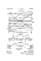
- FIG. 1 is a top plan view of the device in condition for use, one end portion of the frame being broken away;
- Fig. 2 is an end view
- Fig. 3 is a section on the lines 3 3 of Figs. 1 and 2;
- Fig. 4 is a fragmentary view, on an enlarged scale, illustrating details of the cooperating hooked end portions of the main supporting frame and detachable hanger members;
- Fig. 5 is a fragmentary View illustrating further details of the main supporting frame portion of the device
- Fig. 6 is a view, partly in section and partly in end elevation, showing the hanger members of the main supporting frame in folded condition and the detachable side members of the supporting frame together with the detachable article hangers supported for storage on the hooked end portions of the main frame hanger members; and
- Fig. 7 is a fragmentary side elevation of the parts shown in Fig. 6.
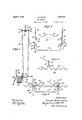
- the numeral 10 designates the central supporting member by which the device, in use, is suspended from the ceiling vof a room or other support by a rope 11.
- the member 10 comprises a plate or sheet metal body having a central aperture 12 for the attach- 1930.
- the metal surrounding said opening being preferably rolled so as to protect the rope from being cut, it being only necessary to form a knot 13 at theend of the rope for supporting the plate 10.
- a suitable swivel member or device (not shown) may be obviously applied to the opening 12 for the attachment and accommodation of the rope 11, if desired.
- the opposite marginal portions 14 of the supporting plate 10 6'0"- ⁇ mounted.
- frame members 16 are attached to the cross members 18 of the frame, by the process of electrical or other method of welding, or any other suitable or approved means of attachment. ther braced by the diagonal stays 19 which are secured to said members 16, as at 20, and to the members 18, as at 21, preferably by a welding process, or in a manner similar to that in which the jointures 17 between the 75 members 16 and 18 are effected.
- the frame members 18 are provided at their opposite ends with looped portions 22V affording hooks for supporting detachable frame members 23, said frame members 23, 8'
- loops or eye extensions 24 are provided on the frame members 23, they being formed either integrally therewith or made separately and welded thereto, for the reception of the hooked end portions 22 of th-e foldable sup- 90.
- the end portions 25 of the hooks 95 22 of one of the foldable supporting frame members 16 are extended only sufficiently to retain the loop or leye extension 24; in place, as shown more clearly in Figs. 2 and 5 of the drawings, but the end portions of the other The frame members 16 and 18 are fur-'V 70 folding frame 16 are extended, i'irst as at 26, substantially at right angles outwardly from the general flat plane of the frame, and then rebent upwardly, as at 27, substantially at right angles to said portion 26, thereby affording hooks of considerable dimensions for supporting the frame members 23, and detachable article hanger members 28 to be now described, in the collapsed or knocked down condition of the device for storage or conveniently packaging the device for shipping.
- the detachable frame members or bars 23 are provided with a ⁇ series of seating portions 29 throughout their length, said seating portions being formed by uniformly crimping the bars, thereby producing substantially V- shaped recesses or notches for the reception of the hooked end portions 30 of the article hanger bars 28, said hooked end portions 3() being formed by first bending the end portions of the members 28: perpendicularly to the main body portion, at 31, and then rebending the extreme end portions 32 in spaced parallel relation to said portions 31. It is urther preferable to form the intermediate portions 33 of the hooks 30 square with respect tothe portions 31 and 32 so that said hooks are substantially rectangular, as shown more clearly in Figs. l and 7 of the drawings.
- the supporting -rame members 16 are opened and the transverseV members 23 are hung thereon with their loops or eye extensions 24 engaged with the respective hooks 22 of said frame members 16,.
- the clothing or other articles to be hung from the device for drying or other purposes are placed upon the individual rods or members 28 and said members are then mounted su-pportingly with their hooked end portions engaged in the corresponding notches or seating portions 29 of said transverse members or bars 23, using as many of said rods or menibers 28 as may be necessary and placing them in properly spaced parallel relation to each other to balance the device which is suspended centrally from the cord or rope 11.
- the device may be suspended from any suitable support but preferably by carrying the cord or rope 11 over a pulley near the ceiling and tying or otherwise adjustably fastening said cord or rope to a hook or cleat located conveniently on the side wall of a room whereby the rack may be raised and lowered at will. In this way the rack may be let down into convenient position for placing the articles thereon and removing them therefrom, and lifted close to the ceiling, at will, where it is out of the way and in the region of greater heat when the device is used as a drying rack.
- a device of the character described comprising a collapsibly loldable supporting frame, transverse supporting members detachably mounted on opposite end portions of said iframe in its operative open condition, and longitudinal article hanger members detachably mounted at their opposite ends on said transverse supporting members.
- a device of the character described comprising a collapsibly Joldable supporting frame, transverse supporting members mounted detachably at the opposite ends of said supporting frame in its operative open condition, said transverse members by their means of attachment to said foldable supporting iframe releasably holding the latter in opened condition, and longitudinal article hanger members detachably mounted at their opposite ends on said transverse supporting members, the article hanger engaging portions of said transverse supporting members being arranged to maintain the mounted article hanger members thereon in variably spaced relation to each other.
- a collapsibly oldable supporting frame comprising a central supporting member and an oppositely disposed pair of frames hingedly mounted on said central supporting member, transverse supporting members detachably mounted on the opposite end portions of said hinged frame members in the open condition of the frame, said transverse members by their means of attachment holding said hinged frame members in their opened relation, a plurality of longitudinal article hanger members detachably secured on said transverse supporting members, and means on said collapsibly foldable supporting frame for storing thereon in its collapsed condition the respect-ive detachable transverse supporting members and longitudinal article hanger members.
- a knockdown and collapsibly foldable structure comprising a pair of supporting trame members having a central hinged connection and hooked end portions, a pair of transverse supporting members having a series of recessed seating portions and a pair of looped portions each interlockingly but detachably secured on the hooked end portions of said first mentioned supporting frame members, and a multiplicity of article hanger rods having hooked end portions interlockingly but detachably secured on said seating portions of said transverse supporting' members.
- a knockdown and collapsibly foldable structure comprising a pair of supporting frame members having a central hinged connection and hooked end portions, a pair of transverse supporting members provided with a series of recessed seating portions and having a pair of looped portions each detachably secured on the hooked end portions of said first mentioned supporting frame members, and a multiplicity of article hanger rods having hooked end portions detachably secured in the seat portions of said transverse supporting members, one of said lirst mentioned hinged frame members having supplemental extensions of its hooked end portionsl whereby in the knocked down condition of the device said transverse supporting members and said article hanger bars may be detachably supported thereon.
- a collapsibly moldable supporting frame comprising a central member and a pair of substantially triangular Wire frames hingedly attached to said central member, the base and inclined members of said frames being braced by internal strut members, said :trames havl ing hooked end portions, transverse supporting members comprising crimped rods affording a series of notched seating portions, said rods being provided with looped lateral eX- tensions detachably secured on the hooked end portions of said first mentioned hinged frames, and article hanger members comprising rods having rebent end portions detachably engaged in the respective notched seat portions of said transverse supporting members.
- a central supporting member having provision for swiveling it upon a support, a pair of triangular frames hingedly supported on said central supporting member, said tri- -I angular frames having end extensions at their bases formed to provide hooks, transverse supporting members detachably engaged with the hooked end portions of said triangular frames whereby to be supported thereon and constitute struts :tor holding said triangular frame members in opened relation to each other, said strut members having
Landscapes
- Holders For Apparel And Elements Relating To Apparel (AREA)
Description
April 5, 1932. 1, V|| EMURE 1,852,631
CLOTHESRACK Filed June 18,' 1930 2 Sheets-Sheet l J. VILLEMURE April 5, 1932.
CLOTHESRACK Filed June 18, 1930 2 Sheets-Sheet 2.
nr @am ,awfw Zwar?? Y.; la P/ Il M j@ Patented Apr. 5, 1932 JOSEPH VILLEMURE, OF NEWBERBY, MICHIGAN CLOTHES RACK Application filed June 18,
- This invention relates to clot-hes racks, and more particularly to devices of that kind for hanging laundered clothing and other articles for drying the same.
f The invention has for its principal objects to produce a simple and inexpensive structure of a collapsible or knockdown character, which is light in weight, yet strong, durableV and practical for the purposes intended, and to attain certain other advantages which will more fully appear in the following description. Y
The invention consists in the general arrangement and in the novel structural fea- 15 tures and parts and combinations and arrangements of parts as hereinafter described and pointed out with particularity in the appended claims.
In the accompanying drawings, illustrating a practical adaptation of the invent-ionff Fig. 1 is a top plan view of the device in condition for use, one end portion of the frame being broken away;
Fig. 2 is an end view;
Fig. 3 is a section on the lines 3 3 of Figs. 1 and 2;
Fig. 4 is a fragmentary view, on an enlarged scale, illustrating details of the cooperating hooked end portions of the main supporting frame and detachable hanger members;
Fig. 5 is a fragmentary View illustrating further details of the main supporting frame portion of the device; Fig. 6 is a view, partly in section and partly in end elevation, showing the hanger members of the main supporting frame in folded condition and the detachable side members of the supporting frame together with the detachable article hangers supported for storage on the hooked end portions of the main frame hanger members; and
Fig. 7 is a fragmentary side elevation of the parts shown in Fig. 6.
Referring now to the drawings, the numeral 10 designates the central supporting member by which the device, in use, is suspended from the ceiling vof a room or other support by a rope 11. As shown, the member 10 comprises a plate or sheet metal body having a central aperture 12 for the attach- 1930. serial No. 461,883.
ment of the rope 11, the metal surrounding said opening being preferably rolled so as to protect the rope from being cut, it being only necessary to form a knot 13 at theend of the rope for supporting the plate 10. However` 575- a suitable swivel member or device (not shown) may be obviously applied to the opening 12 for the attachment and accommodation of the rope 11, if desired. The opposite marginal portions 14 of the supporting plate 10 6'0"-` mounted. The outer end portions 17 of the 35m;
The frame members 18 are provided at their opposite ends with looped portions 22V affording hooks for supporting detachable frame members 23, said frame members 23, 8'
as well as the aforesaid frame members 16, 18 and 19, being preferably composed of wire which is galvanized or otherwise coated, or obviously composed of an alloy which is resistant to corrosion. As shown, loops or eye extensions 24 are provided on the frame members 23, they being formed either integrally therewith or made separately and welded thereto, for the reception of the hooked end portions 22 of th-e foldable sup- 90.
porting frame members, whereby said detachable members 23 are supported and the supporting frames 16 are held in ppened condi tion.
Preferably, the end portions 25 of the hooks 95 22 of one of the foldable supporting frame members 16 are extended only sufficiently to retain the loop or leye extension 24; in place, as shown more clearly in Figs. 2 and 5 of the drawings, but the end portions of the other The frame members 16 and 18 are fur-'V 70 folding frame 16 are extended, i'irst as at 26, substantially at right angles outwardly from the general flat plane of the frame, and then rebent upwardly, as at 27, substantially at right angles to said portion 26, thereby affording hooks of considerable dimensions for supporting the frame members 23, and detachable article hanger members 28 to be now described, in the collapsed or knocked down condition of the device for storage or conveniently packaging the device for shipping.
The detachable frame members or bars 23 are provided with a` series of seating portions 29 throughout their length, said seating portions being formed by uniformly crimping the bars, thereby producing substantially V- shaped recesses or notches for the reception of the hooked end portions 30 of the article hanger bars 28, said hooked end portions 3() being formed by first bending the end portions of the members 28: perpendicularly to the main body portion, at 31, and then rebending the extreme end portions 32 in spaced parallel relation to said portions 31. It is urther preferable to form the intermediate portions 33 of the hooks 30 square with respect tothe portions 31 and 32 so that said hooks are substantially rectangular, as shown more clearly in Figs. l and 7 of the drawings. By this provision, when the article hanger lmembers 28 are supported with their hooked portions 30 engaged with the respective bars 23, as shown in Fig. 3 and mo-re clearly in Fig. l, the portions 31 of said hooks 30 are closely contiguous to the members 23, in the opened wor-king condition of the device, but when the device is knocked down, the supporting frame members 16 are folded in collapsed condition, as shown in Fig. 6, in which condition the crimped frame bars 23 are supported on the hooked extensions 26 of one of the frame members 16, as shown in Fig. 7. In this condition of the supporting frame members 16 the hooked portions 3 0 of the article hanger members 28 are engaged over th-e said hooked portions 26 of the frame member 16, the rebent end portions 32 of said members 28'being closely contiguous to said portions 26. It will thus be seen that the relative distance between the portions 31 and32 of the hooks 3() of said members 28 adapt the members 28 for these two particular ways of supporting them.
In using the device the supporting -rame members 16 are opened and the transverseV members 23 are hung thereon with their loops or eye extensions 24 engaged with the respective hooks 22 of said frame members 16,. The clothing or other articles to be hung from the device for drying or other purposes are placed upon the individual rods or members 28 and said members are then mounted su-pportingly with their hooked end portions engaged in the corresponding notches or seating portions 29 of said transverse members or bars 23, using as many of said rods or menibers 28 as may be necessary and placing them in properly spaced parallel relation to each other to balance the device which is suspended centrally from the cord or rope 11. In practice, the device may be suspended from any suitable support but preferably by carrying the cord or rope 11 over a pulley near the ceiling and tying or otherwise adjustably fastening said cord or rope to a hook or cleat located conveniently on the side wall of a room whereby the rack may be raised and lowered at will. In this way the rack may be let down into convenient position for placing the articles thereon and removing them therefrom, and lifted close to the ceiling, at will, where it is out of the way and in the region of greater heat when the device is used as a drying rack.
Obviously, the structure admits of considerable modilication in the details of its parts and their relative arrangements without in the least departing from the spirit and scope of the invention as defined by the appended claims. The invention, therefore, is not limited to the specific construction and arrangement shown in the accompanying drawings.
Having thus described my invention, what I claim as new and desire to secure by Letters Patent is:
1. A device of the character described, comprising a collapsibly loldable supporting frame, transverse supporting members detachably mounted on opposite end portions of said iframe in its operative open condition, and longitudinal article hanger members detachably mounted at their opposite ends on said transverse supporting members.
2. A device of the character described, comprising a collapsibly Joldable supporting frame, transverse supporting members mounted detachably at the opposite ends of said supporting frame in its operative open condition, said transverse members by their means of attachment to said foldable supporting iframe releasably holding the latter in opened condition, and longitudinal article hanger members detachably mounted at their opposite ends on said transverse supporting members, the article hanger engaging portions of said transverse supporting members being arranged to maintain the mounted article hanger members thereon in variably spaced relation to each other.
3. ln a device of the character described, a collapsibly oldable supporting frame comprising a central supporting member and an oppositely disposed pair of frames hingedly mounted on said central suporting member, transverse supporting members detachably mounted on the opposite end portions of said hinged frame members in the open condition of the frame, said transverse members by their means of attachment holding said hinged frame members in their opened relation, a plurality of longitudinal article hanger members detachably secured on said transverse supporting members, and means on said collapsibly foldable supporting frame for storing thereon in its collapsed condition the respect-ive detachable transverse supporting members and longitudinal article hanger members.
4. In a device of the character described, a knockdown and collapsibly foldable structure comprising a pair of supporting trame members having a central hinged connection and hooked end portions, a pair of transverse supporting members having a series of recessed seating portions and a pair of looped portions each interlockingly but detachably secured on the hooked end portions of said first mentioned supporting frame members, and a multiplicity of article hanger rods having hooked end portions interlockingly but detachably secured on said seating portions of said transverse supporting' members.
5. In a device of the character described, a knockdown and collapsibly foldable structure comprising a pair of supporting frame members having a central hinged connection and hooked end portions, a pair of transverse supporting members provided with a series of recessed seating portions and having a pair of looped portions each detachably secured on the hooked end portions of said first mentioned supporting frame members, and a multiplicity of article hanger rods having hooked end portions detachably secured in the seat portions of said transverse supporting members, one of said lirst mentioned hinged frame members having supplemental extensions of its hooked end portionsl whereby in the knocked down condition of the device said transverse supporting members and said article hanger bars may be detachably supported thereon.
6. In a device of the character described, a collapsibly moldable supporting frame comprising a central member and a pair of substantially triangular Wire frames hingedly attached to said central member, the base and inclined members of said frames being braced by internal strut members, said :trames havl ing hooked end portions, transverse supporting members comprising crimped rods affording a series of notched seating portions, said rods being provided with looped lateral eX- tensions detachably secured on the hooked end portions of said first mentioned hinged frames, and article hanger members comprising rods having rebent end portions detachably engaged in the respective notched seat portions of said transverse supporting members.
7. In a device of the character described, a central supporting member having provision for swiveling it upon a support, a pair of triangular frames hingedly supported on said central supporting member, said tri- -I angular frames having end extensions at their bases formed to provide hooks, transverse supporting members detachably engaged with the hooked end portions of said triangular frames whereby to be supported thereon and constitute struts :tor holding said triangular frame members in opened relation to each other, said strut members having
Priority Applications (1)
| Application Number | Priority Date | Filing Date | Title |
|---|---|---|---|
| US461883A US1852631A (en) | 1930-06-13 | 1930-06-13 | Clothes rack |
Applications Claiming Priority (1)
| Application Number | Priority Date | Filing Date | Title |
|---|---|---|---|
| US461883A US1852631A (en) | 1930-06-13 | 1930-06-13 | Clothes rack |
Publications (1)
| Publication Number | Publication Date |
|---|---|
| US1852631A true US1852631A (en) | 1932-04-05 |
Family
ID=23834326
Family Applications (1)
| Application Number | Title | Priority Date | Filing Date |
|---|---|---|---|
| US461883A Expired - Lifetime US1852631A (en) | 1930-06-13 | 1930-06-13 | Clothes rack |
Country Status (1)
| Country | Link |
|---|---|
| US (1) | US1852631A (en) |
Cited By (3)
| Publication number | Priority date | Publication date | Assignee | Title |
|---|---|---|---|---|
| US3370715A (en) * | 1965-10-22 | 1968-02-27 | Kolozsvari Paul | Necktie hangers |
| US20080185353A1 (en) * | 2007-01-05 | 2008-08-07 | Interdesign, Inc. | Utility items made with rods of oval construction |
| US20220081829A1 (en) * | 2020-09-17 | 2022-03-17 | Jennifer G. Brame | Apparatuses and methods for a removable structural support |
-
1930
- 1930-06-13 US US461883A patent/US1852631A/en not_active Expired - Lifetime
Cited By (5)
| Publication number | Priority date | Publication date | Assignee | Title |
|---|---|---|---|---|
| US3370715A (en) * | 1965-10-22 | 1968-02-27 | Kolozsvari Paul | Necktie hangers |
| US20080185353A1 (en) * | 2007-01-05 | 2008-08-07 | Interdesign, Inc. | Utility items made with rods of oval construction |
| US8915384B2 (en) * | 2007-01-05 | 2014-12-23 | Interdesign, Inc. | Utility items made with rods of oval construction |
| US20220081829A1 (en) * | 2020-09-17 | 2022-03-17 | Jennifer G. Brame | Apparatuses and methods for a removable structural support |
| US12006622B2 (en) * | 2020-09-17 | 2024-06-11 | Jennifer G. Brame | Apparatuses and methods for a removable structural support |
Similar Documents
| Publication | Publication Date | Title |
|---|---|---|
| US2271941A (en) | Garment hanger | |
| US4744537A (en) | Hanger bracket | |
| US20090261050A1 (en) | Bag storage and loading unit | |
| US1752985A (en) | Display rack | |
| US1464160A (en) | Meat hook | |
| US2274772A (en) | Clothes rack | |
| US1852631A (en) | Clothes rack | |
| US5143214A (en) | Hanging garment storage bag | |
| US5971172A (en) | Folding artificial Christmas tree frame | |
| US2295736A (en) | Foldable rack | |
| US1293953A (en) | Clothes-hanger. | |
| US1159192A (en) | Support for clothes-lines and hammocks. | |
| US1010633A (en) | Picture-hanger. | |
| US1802149A (en) | Clothes-checking apparatus | |
| US1184724A (en) | Garment-hanger. | |
| US2053633A (en) | Garment hanger | |
| US973414A (en) | Bag-holder. | |
| US1352556A (en) | Garment-hanger | |
| US1407912A (en) | Foldable rack | |
| US2047093A (en) | Portable wardrobe | |
| US1605510A (en) | Tub bracket | |
| US1005047A (en) | Clothes-line. | |
| KR960010443Y1 (en) | Collapsible holder of flower pot | |
| US2198299A (en) | Clothes drier | |
| US795619A (en) | Combination clothes-rack, wardrobe, and bath-cabinet. |