US1852614A - Flashover relay - Google Patents
Flashover relay Download PDFInfo
- Publication number
- US1852614A US1852614A US471662A US47166230A US1852614A US 1852614 A US1852614 A US 1852614A US 471662 A US471662 A US 471662A US 47166230 A US47166230 A US 47166230A US 1852614 A US1852614 A US 1852614A
- Authority
- US
- United States
- Prior art keywords
- relay
- armature
- casing
- target
- conductor
- Prior art date
- Legal status (The legal status is an assumption and is not a legal conclusion. Google has not performed a legal analysis and makes no representation as to the accuracy of the status listed.)
- Expired - Lifetime
Links
Images

Classifications
-
- H—ELECTRICITY
- H01—ELECTRIC ELEMENTS
- H01H—ELECTRIC SWITCHES; RELAYS; SELECTORS; EMERGENCY PROTECTIVE DEVICES
- H01H71/00—Details of the protective switches or relays covered by groups H01H73/00 - H01H83/00
- H01H71/10—Operating or release mechanisms
- H01H71/12—Automatic release mechanisms with or without manual release
- H01H71/24—Electromagnetic mechanisms
- H01H71/2472—Electromagnetic mechanisms with rotatable armatures
-
- H—ELECTRICITY
- H01—ELECTRIC ELEMENTS
- H01H—ELECTRIC SWITCHES; RELAYS; SELECTORS; EMERGENCY PROTECTIVE DEVICES
- H01H71/00—Details of the protective switches or relays covered by groups H01H73/00 - H01H83/00
- H01H71/10—Operating or release mechanisms
- H01H71/12—Automatic release mechanisms with or without manual release
- H01H71/24—Electromagnetic mechanisms
- H01H71/2481—Electromagnetic mechanisms characterised by the coil design
Definitions
- Our invention relates to electrical relays and more particularly to relays of the electromagnetic type.
- a further object of our invention is to provide,in combination with a circuit conductor or bus bar, a relay including a casing having apertured side walls for receiving said conductor or bus bar in through relation and in inductive relation with respect to the relay mechanism within the casing.
- Another object of the invention is the provision in conjunction with a relay armature, of means, operable in response to the actuation of said armature, to accomplish the dual function of affording an indication that the relay has operated and maintaining the armature thereof in actuated position.
- a relay having an operating mechanism comprising a magnetic element of substantially C-shape, comprising an alloy of iron and nickel, and an armature pivotally mounted with respect to the open end of said magnetic element for movement under the influence of the flux traversing said element.
- Suitable contacts may be disposed to be controlled by said armature, and a combined latch and indicator means may be provided, as hereinafter more fully described.
- a casing completely encloses the relay mechanism and is provided with apertures in the side walls thereof which are in axial stalled, the bus bar or conductor is substan tially surrounded by said magnetic element.
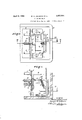
- Figure 1 is a plan view of a relay constructed in accordance with our invention, the cover thereof being removed,
- Fig. 2 is a view, taken on the line IIII of Fig. 1, with the cover in operative position,
- Fig. 3 is an enlarged detail view of the armature and indicator assembly, as shown in Fig. 1, and
- Fig. 4 is a view, in vertical section, taken on the line IVIV of Fig. 3.
- a circuit conductor or bus bar 1 constitutes a usual ground bus, which is connected from electrical apparatus to ground, or it may be any ordinary circuit conductor in an electrical systern.
- a casing 2 which, in the present embodiment, comprises an outlet box, is provided with apertures in the side walls thereof somewhat larger, in cross-sectional dimensions, than the bus-bar conductor 1 to permit the bus bar to extend through the casing.
- a sleeve 3 of insulating material may also extend through the apertures to electrically insulate the casing from thebus conductor.
- a conduit nipple 4 is provided, for bringing out the leads from the relay contacts, and a cover 5 may be employed to close the open face of the casing, as illustrated.
- the operating mechanism of the relay comprises a magnetic element 6, substantially of C-shape, as shown more clearly in Fig. 2, having one leg thereof suitably secured to the back of the casing.
- the magnet is preferably of an alloy containing iron and a substantial percentage of nickel and may be of the composition disclosed in the patent to Chubb No. 1,277,38A issued Sept. 8, 1918. As set forth in that patent, an alloy of this general type becomes substantially saturated when subjected to low magnetizing forces and has substantially no residual magnetic characteristics.
- the arrangement is such that, when the magnet is secured within the casing, the two legs thereof are disposed on opposite sides of the axis of the aligned openings in the side walls of the casing, whereby the bus bar, when inserted therethrough, will be disposed between the legs of the magnet and be substantially surrounded thereby.
- An armature 7 also preferably of a nickeliron alloy of substantially the same composition as that of the magnet 6, is pivot-ally secured to a bracket 8 mounted on the casing 2. The armature is free to move, therefore, under the influence of the flux traversing the magnet, to complete a magnetic circuit about the bus conductor.
- Acontact plate 9 may be secured to the free end of the armature, and a bridging contact 10, carried thereby, may be arranged to cooperate with adjustable contacts 11 to complete a circuit-breaker tripping or control circuit.
- the contact 10 bridges the contacts 11, in the present embodiment, but, obviously,
- the minimum values of current at which the armature is attracted to close the contacts 10 and 11 may be adjustably predetermined by means of a compression spring 12 having one end thereof engaging the contact plate 9 and the other end thereof engaging an adjustably mounted plate 13.
- the relay may be mounted in any position and, by a simple manipulation of the adjustingplate 13, special calibrations for the instrument for different positions thereof are unnecessary.
- the plate 13 when the bus bar with which the relay is associated extends in a vertical direction, the plate 13 should be positioned as shown with the letter D cooperating with a stationary index 14. If the bus bar extends horizontally, and the nipple 4 is at the bottom of the casing, the plate 13 should be moved so that the index 14 cooperates with the letter C, to thereby alter the effective force of spring 12.
- the relay may be posu tioned in any one of four positions and, when the plate 13 is so adjusted that the letter appearing right-side-up to the observer cooperates with the index 14, the proper calibration for that relay position is obtained.
- a shading coil or loop 15 may be associated with one of the pole tips of the magnet 6. Since the theory and effect of such an expedient is well known in the art, further discussion thereof is unnecessary.
- the magnet 6 By constructing the magnet 6 of a nickeliron alloy, however, it has been found that the armature will not stick appreciably at excessively high currents, and the maximum current to which the relay may be subjected is limited only by the current-carrying capacity of the bus bar. Further, when the bus bar is deenergized, the armature does not stick in position and, in fact, the weight of the armature, in addition to the slight contact pressure, is sufiicient to cause the disengagement of the contacts 10 and 11.
- the relay may be easily mounted for operation by merely slipping it on a bus bar or other conductor, and the bus bar or conductor is suiiicient to support the relay in operative position.
- the busbar will never engage the casing, therebv avoiding the usual hazards incident to relay installation.
- relays of the above type it is usually dosirable to provide means for indicating that the relay has operated.
- an operation indicator which is associated with the relay armature in such manner that an operation indication is afforded, and the indicator is maintained in indicating position until manually reset, and the indicator, when actuated, maintains the relay contacts closed.
- bracket 8 above referred to, is provided with upstanding plate portions 24 having aligned slots 25 therein.
- a coil spring 18 or other suitable biasing means may be secured. at one end thereof, to the bracket 8 and, at the other end thereof,
- the point of engagement of the spring and target is somewhat off-center with respect to the pivotal axis of the target so that the latter will always be definitely biased to the one or the other limiting position thereof.
- a loop 19 is secured to the armature assembly and is provided with a lower portion parallel to the plane of the target 16 and extending between the target and the bracket 8.
- the elements are normally in the position shown in Fig. 2, with the target 16 maintained in that position by the spring 18.
- the loop 19 supported thereby engages the target and moves it toward the armature. It is to be understood that, in this operation, it is only necessary to raise the target to such position that the end of spring 18 is moved to the opposite side of the axis of the target trunnions. Thereafter, the movement of the target will continue under the influence of the spring 18.
- the target Upon the completion of this movement, the target is in the position indicated in Figs. 3 and 4, with the upper or free edge thereof in engagement with the armature portion 9.
- the force exerted by spring 18 is sufiicient to maintain the target and armature in this position and, accordingly, maintain the relay contacts 10 and 11 in closed position until the target is reset.
- a resilient strip 20 secured, at one end thereof, to the bracket 8, and having its free end extended to cooperate with an angular extension 21 on said target may be provided.
- a reset-rod or plunger 22 may extend through a wall of the relay casing and be so disposed,with respect to said resilient strip 20, that, upon movement of the plunger into the casing, the end of the plunger will engage the strip 20 to effect movement of the free end thereof into engagement with the target extension 21.
- the relay cover 5 may be provided with atransparent portion 23 to permit observation of the target and the moving parts of the relay.
- the means for mounting the armature may be varied within wide limits, and the means 13 for adjusting the pick-up value of the armature may be modified to adapt the relay to the exigencies of a particular installation.
- the relay may be emloyed as a fiashover. relay for association with a ground bus or it may be employed as an instantaneous overload relay. When employed for zero-current protection on heavycurrent lines, the use of the usual expensive low-voltage or no-current relay is unnecessary.
- a relay including a magnet of substantially C-shape adapted to surround the conductor in the magnetic field thereof, an armature mounted for movement adjacent to the open end of said magnet whereby, when the flux threading said magnet attains a predetermined value, said armature is attracted to said magnet to close the magnetic circuit surrounding said conductor.
- a relay including a casing having aligned apertures in the walls thereof for receiving said conductor, and a magnetic element of substantially C-shape, within said casing and disposed to substantially surround said conductor when said casing and said conductor are in operative relation.
- a circuit conductor comprising a magnetic element and a casing therefor, said casing having apertures for removably receiving said conductor in inductive relation to said magnetic element.
- a relay casing having apertured side walls to permit said bus bar to extend therethrough, a magnetic element comprising a nickel-iron alloy within said casing and mounted in inductive relation to said bus bar, and an armature controlled by said magnetic element.
- a relay the combination with an operating element including a magnet adapted to surround a circuit conductor to be energized thereby, of a casing for said relay comprising a box having apertured side walls to receive said conductor in through relation, said apertures and magnet being in axial alignment.
- a casing having apertured side walls for receiving a circuit conductor in through relation, a relay element within said casing comprising a magnetic element of substantially C-shape disposed in axial alignment with said apertures, an armature disposed for actuation under the influence of said magnetic element, and means for adjusting the pick-up value of said armature.
- a casing having apertured side Walls for receiving a circuit con duetor in through relation, a relay element Within said casing comprising a magnetic element of substantially C-shape in axial alignment with said apertures, an armature disposed for actuation under the influences of said magnetic element, and means for adj ustin the pick-up value of said armature in accor ance with the position of said casing.
Landscapes
- Physics & Mathematics (AREA)
- Electromagnetism (AREA)
- Breakers (AREA)
Description
Ap 1932- w. v. JOHNSON ET AL FLASHOVER RELAY Original Filed May 10, 1929 I 2 Sheets-Sheet 1 mmm':
III III Hill III INVENTORS Welfon MJo/flvsan and Merrie/f 7?. Fe/dmann O f v ATTORNEY W. V. JOHNSON ET FLASHOVER RELAY April 5, 1932.
Original Filed May 10,
1929 2 Sheets-Sheet 2 j INVENTOR ll elzan KJzwnson and flerz'z'clffiiidmann I BY ATTCRNEY Patented Apr. 5, 1932 UNITED STATES PATENT OFFICE WELTON V. JOHNSON AND MERRICK R. FELDMANN, OF NUTLEY, NEW JERSEY, ASSIGNORS TO WESTINGHOUSE ELECTRIC AND MANUFACTURING COMPANY, A
CORPORATION OF PENNSYLVANIA FLASHOVER RELAY Original application filed May 10, 1929, Serial No. 362,012. Divided and this application filed July 30, 1930.
' Serial No. 471,662.
This application is a division of United States application, Serial No. 362,012, filed May 10, 1929.
Our invention relates to electrical relays and more particularly to relays of the electromagnetic type.
It is an object of our invention to provide a magnetic relay which shall be substantially instantaneous in operation, when employed for over-current protective purposes.
It is a further-object of our invention to provide a relay which may be operated in conjunction with either a direct-current or an alternating-current circuit and including means whereby the relay is unusually reliable and quiet in operation.
A further object of our invention is to provide,in combination with a circuit conductor or bus bar, a relay including a casing having apertured side walls for receiving said conductor or bus bar in through relation and in inductive relation with respect to the relay mechanism within the casing.
Another object of the invention is the provision in conjunction with a relay armature, of means, operable in response to the actuation of said armature, to accomplish the dual function of affording an indication that the relay has operated and maintaining the armature thereof in actuated position.
In practicing our invention, we provide a relay having an operating mechanism comprising a magnetic element of substantially C-shape, comprising an alloy of iron and nickel, and an armature pivotally mounted with respect to the open end of said magnetic element for movement under the influence of the flux traversing said element. Suitable contacts may be disposed to be controlled by said armature, and a combined latch and indicator means may be provided, as hereinafter more fully described.
A casing completely encloses the relay mechanism and is provided with apertures in the side walls thereof which are in axial stalled, the bus bar or conductor is substan tially surrounded by said magnetic element.
In the drawings, Figure 1 is a plan view of a relay constructed in accordance with our invention, the cover thereof being removed,
Fig. 2 is a view, taken on the line IIII of Fig. 1, with the cover in operative position,
Fig. 3 is an enlarged detail view of the armature and indicator assembly, as shown in Fig. 1, and
Fig. 4 is a view, in vertical section, taken on the line IVIV of Fig. 3.
Referring to the drawings, and more particularly to Figs. 1 and 2 thereof, a circuit conductor or bus bar 1, constitutes a usual ground bus, which is connected from electrical apparatus to ground, or it may be any ordinary circuit conductor in an electrical systern.
A casing 2, which, in the present embodiment, comprises an outlet box, is provided with apertures in the side walls thereof somewhat larger, in cross-sectional dimensions, than the bus-bar conductor 1 to permit the bus bar to extend through the casing. A sleeve 3 of insulating material may also extend through the apertures to electrically insulate the casing from thebus conductor.
A conduit nipple 4: is provided, for bringing out the leads from the relay contacts, and a cover 5 may be employed to close the open face of the casing, as illustrated.
The operating mechanism of the relay comprises a magnetic element 6, substantially of C-shape, as shown more clearly in Fig. 2, having one leg thereof suitably secured to the back of the casing. The magnet is preferably of an alloy containing iron and a substantial percentage of nickel and may be of the composition disclosed in the patent to Chubb No. 1,277,38A issued Sept. 8, 1918. As set forth in that patent, an alloy of this general type becomes substantially saturated when subjected to low magnetizing forces and has substantially no residual magnetic characteristics.
The arrangement is such that, when the magnet is secured within the casing, the two legs thereof are disposed on opposite sides of the axis of the aligned openings in the side walls of the casing, whereby the bus bar, when inserted therethrough, will be disposed between the legs of the magnet and be substantially surrounded thereby.
An armature 7 also preferably of a nickeliron alloy of substantially the same composition as that of the magnet 6, is pivot-ally secured to a bracket 8 mounted on the casing 2. The armature is free to move, therefore, under the influence of the flux traversing the magnet, to complete a magnetic circuit about the bus conductor.
Acontact plate 9 may be secured to the free end of the armature, and a bridging contact 10, carried thereby, may be arranged to cooperate with adjustable contacts 11 to complete a circuit-breaker tripping or control circuit. The contact 10 bridges the contacts 11, in the present embodiment, but, obviously,
- the present invention is not limited to that arrangement.
The minimum values of current at which the armature is attracted to close the contacts 10 and 11 may be adjustably predetermined by means of a compression spring 12 having one end thereof engaging the contact plate 9 and the other end thereof engaging an adjustably mounted plate 13.
With a construction as described, the relay may be mounted in any position and, by a simple manipulation of the adjustingplate 13, special calibrations for the instrument for different positions thereof are unnecessary. For example, referring more specifically to Fig. 1, when the bus bar with which the relay is associated extends in a vertical direction, the plate 13 should be positioned as shown with the letter D cooperating with a stationary index 14. If the bus bar extends horizontally, and the nipple 4 is at the bottom of the casing, the plate 13 should be moved so that the index 14 cooperates with the letter C, to thereby alter the effective force of spring 12. In other words, the relay may be posu tioned in any one of four positions and, when the plate 13 is so adjusted that the letter appearing right-side-up to the observer cooperates with the index 14, the proper calibration for that relay position is obtained.
In order to assure quiet or non-chattering operation, when the bus bar is traversed by alternating currents, a shading coil or loop 15 (Fig. 2) may be associated with one of the pole tips of the magnet 6. Since the theory and effect of such an expedient is well known in the art, further discussion thereof is unnecessary.
In the rather extensive investigation and study of this type of relay incident to the development of the present form, it was found that, when the magnet 6 is constructed of ordinary Norway iron or similar magnetic material, the armature 7 when in attracted position, cannot be released because of the residual magnetic characteristics of the iron. On
the other hand, when it was attempted to remedy this faulty operation by installing a relatively heavy spring in place of the spring 12, the value of current required to pick up the armature was undesirably heavy, and the sensitivity of the relay was undesirably affected. It was also found practically impossible to calibrate the relay and maintain the calibration under operating conditions.
By constructing the magnet 6 of a nickeliron alloy, however, it has been found that the armature will not stick appreciably at excessively high currents, and the maximum current to which the relay may be subjected is limited only by the current-carrying capacity of the bus bar. Further, when the bus bar is deenergized, the armature does not stick in position and, in fact, the weight of the armature, in addition to the slight contact pressure, is sufiicient to cause the disengagement of the contacts 10 and 11.
It is apparent from the above description that we have devised arelay construction which is unusually simple and cheap and which is substantially instantaneous in operation, when associated with either direct or alternatingcurrent circuits. The armature willnot chatter on either alternating or direct current and it will not stick in attracted positions, irrespective ofthe magnitude of the current traversing the associated circuit. Further, bythe above construction, it is unnecessary to provide the usual energizing windings, and the provision of terminals for connecting the relay to the associated circuit is accordingly avoided.
The relay may be easily mounted for operation by merely slipping it on a bus bar or other conductor, and the bus bar or conductor is suiiicient to support the relay in operative position. In view of the provision of the insulating sleeve 3, the busbarwill never engage the casing, therebv avoiding the usual hazards incident to relay installation.
In relays of the above type, it is usually dosirable to provide means for indicating that the relay has operated. To that end, we provide an operation indicator which is associated with the relay armature in such manner that an operation indication is afforded, and the indicator is maintained in indicating position until manually reset, and the indicator, when actuated, maintains the relay contacts closed.
Referring more particularly to Figs. 3 and 4-, the bracket 8, above referred to, is provided with upstanding plate portions 24 having aligned slots 25 therein. A plate or target 16, having projecting trunnions 17 for reception in said slots, is supported for pivotal movement about the axis defined by said trunnions.
A coil spring 18 or other suitable biasing means, may be secured. at one end thereof, to the bracket 8 and, at the other end thereof,
to the target 16. It will be noted that the point of engagement of the spring and target is somewhat off-center with respect to the pivotal axis of the target so that the latter will always be definitely biased to the one or the other limiting position thereof.
A loop 19 is secured to the armature assembly and is provided with a lower portion parallel to the plane of the target 16 and extending between the target and the bracket 8.
In operation, the elements are normally in the position shown in Fig. 2, with the target 16 maintained in that position by the spring 18. Upon actuation of the armature 7, the loop 19 supported thereby engages the target and moves it toward the armature. It is to be understood that, in this operation, it is only necessary to raise the target to such position that the end of spring 18 is moved to the opposite side of the axis of the target trunnions. Thereafter, the movement of the target will continue under the influence of the spring 18.
Upon the completion of this movement, the target is in the position indicated in Figs. 3 and 4, with the upper or free edge thereof in engagement with the armature portion 9. The force exerted by spring 18 is sufiicient to maintain the target and armature in this position and, accordingly, maintain the relay contacts 10 and 11 in closed position until the target is reset.
In order to reset the indicator and ermit the return of the armature to norma position, a resilient strip 20 secured, at one end thereof, to the bracket 8, and having its free end extended to cooperate with an angular extension 21 on said target, may be provided. A reset-rod or plunger 22 may extend through a wall of the relay casing and be so disposed,with respect to said resilient strip 20, that, upon movement of the plunger into the casing, the end of the plunger will engage the strip 20 to effect movement of the free end thereof into engagement with the target extension 21.
Continued movement of the plunger causes pivotal movement of the target to a position where the spring 18 has passed through its dead-center position with respect to the pivotal axis of the target, and the target is moved, thereafter, to its non-indicating position, under the influence of the spring 1 As illustrated in Fig. 2, the relay cover 5 may be provided with atransparent portion 23 to permit observation of the target and the moving parts of the relay.
Quite obviously, a great many changes may be made in the structure described without departing from the spirit of the invention. For example, the means for mounting the armature, as well as the specific contact construction shown, may be varied within wide limits, and the means 13 for adjusting the pick-up value of the armature may be modified to adapt the relay to the exigencies of a particular installation.
As previously indicated, the relay may be emloyed as a fiashover. relay for association with a ground bus or it may be employed as an instantaneous overload relay. When employed for zero-current protection on heavycurrent lines, the use of the usual expensive low-voltage or no-current relay is unnecessary.
Various other modifications may be made in our invention without departing from the spirit and scope thereof and we desire, therefore, that only such limitations shall be placed thereon as are imposed by the prior art and are set forth in the appended claims.
We claim as our invention:
1. In combination with a circuit conductor, a relay including a magnet of substantially C-shape adapted to surround the conductor in the magnetic field thereof, an armature mounted for movement adjacent to the open end of said magnet whereby, when the flux threading said magnet attains a predetermined value, said armature is attracted to said magnet to close the magnetic circuit surrounding said conductor.
2. In combination with a circuit conductor, a relay including a casing having aligned apertures in the walls thereof for receiving said conductor, and a magnetic element of substantially C-shape, within said casing and disposed to substantially surround said conductor when said casing and said conductor are in operative relation.
3. In combination, a circuit conductor, a relay comprising a magnetic element and a casing therefor, said casing having apertures for removably receiving said conductor in inductive relation to said magnetic element.
4:. In combination with a bus bar, a relay casing having apertured side walls to permit said bus bar to extend therethrough, a magnetic element comprising a nickel-iron alloy within said casing and mounted in inductive relation to said bus bar, and an armature controlled by said magnetic element.
5. In a relay, the combination with an operating element including a magnet adapted to surround a circuit conductor to be energized thereby, of a casing for said relay comprising a box having apertured side walls to receive said conductor in through relation, said apertures and magnet being in axial alignment.
6. In combination, a casing having apertured side walls for receiving a circuit conductor in through relation, a relay element within said casing comprising a magnetic element of substantially C-shape disposed in axial alignment with said apertures, an armature disposed for actuation under the influence of said magnetic element, and means for adjusting the pick-up value of said armature.
.7. In combination, a casing having apertured side Walls for receiving a circuit con duetor in through relation, a relay element Within said casing comprising a magnetic element of substantially C-shape in axial alignment with said apertures, an armature disposed for actuation under the influences of said magnetic element, and means for adj ustin the pick-up value of said armature in accor ance with the position of said casing.
In testimony whereof, We have hereunto subscribed our names this 16 day of July, 1930.
WELTON V. J OHNSON. MERRICK R. FELDMANN.
Priority Applications (1)
| Application Number | Priority Date | Filing Date | Title |
|---|---|---|---|
| US471662A US1852614A (en) | 1929-05-10 | 1930-07-30 | Flashover relay |
Applications Claiming Priority (2)
| Application Number | Priority Date | Filing Date | Title |
|---|---|---|---|
| US36201229A | 1929-05-10 | 1929-05-10 | |
| US471662A US1852614A (en) | 1929-05-10 | 1930-07-30 | Flashover relay |
Publications (1)
| Publication Number | Publication Date |
|---|---|
| US1852614A true US1852614A (en) | 1932-04-05 |
Family
ID=27001523
Family Applications (1)
| Application Number | Title | Priority Date | Filing Date |
|---|---|---|---|
| US471662A Expired - Lifetime US1852614A (en) | 1929-05-10 | 1930-07-30 | Flashover relay |
Country Status (1)
| Country | Link |
|---|---|
| US (1) | US1852614A (en) |
Cited By (7)
| Publication number | Priority date | Publication date | Assignee | Title |
|---|---|---|---|---|
| DE758356C (en) * | 1938-06-29 | 1953-03-02 | Siemens Schuckertwerke A G | Synchronous AC drive |
| US2952802A (en) * | 1957-12-10 | 1960-09-13 | Michelson Carlyle | Electromagnetic release mechanism |
| US3210750A (en) * | 1961-03-23 | 1965-10-05 | Westinghouse Electric Corp | Cable terminator with fault-current indicator therefor |
| US3213231A (en) * | 1964-10-26 | 1965-10-19 | Udylite Corp | Adjustable magnetic switch |
| US3257533A (en) * | 1965-04-23 | 1966-06-21 | Westinghouse Electric Corp | Fluid-blast circuit interrupters with two selectively-operated fluid-blast sources |
| US3270163A (en) * | 1965-05-19 | 1966-08-30 | Automatic Switch Co | Coil-less relay for use on bus bars |
| US3302142A (en) * | 1964-03-26 | 1967-01-31 | Piechotta Josef Max | Load responsive switch apparatus |
-
1930
- 1930-07-30 US US471662A patent/US1852614A/en not_active Expired - Lifetime
Cited By (7)
| Publication number | Priority date | Publication date | Assignee | Title |
|---|---|---|---|---|
| DE758356C (en) * | 1938-06-29 | 1953-03-02 | Siemens Schuckertwerke A G | Synchronous AC drive |
| US2952802A (en) * | 1957-12-10 | 1960-09-13 | Michelson Carlyle | Electromagnetic release mechanism |
| US3210750A (en) * | 1961-03-23 | 1965-10-05 | Westinghouse Electric Corp | Cable terminator with fault-current indicator therefor |
| US3302142A (en) * | 1964-03-26 | 1967-01-31 | Piechotta Josef Max | Load responsive switch apparatus |
| US3213231A (en) * | 1964-10-26 | 1965-10-19 | Udylite Corp | Adjustable magnetic switch |
| US3257533A (en) * | 1965-04-23 | 1966-06-21 | Westinghouse Electric Corp | Fluid-blast circuit interrupters with two selectively-operated fluid-blast sources |
| US3270163A (en) * | 1965-05-19 | 1966-08-30 | Automatic Switch Co | Coil-less relay for use on bus bars |
Similar Documents
| Publication | Publication Date | Title |
|---|---|---|
| US4081852A (en) | Ground fault circuit breaker | |
| US1852614A (en) | Flashover relay | |
| US3806845A (en) | Ground fault interrupter | |
| GB501885A (en) | Improvements in, and connected with, thermally-tripped automatic circuit breakers and similar electrical switchgear | |
| US3745414A (en) | Ground fault circuit interrupter | |
| US3227925A (en) | Control for switch means | |
| US3863186A (en) | Three phase remote control circuit breaker | |
| US3688227A (en) | Impedance protector | |
| US1934663A (en) | High-speed impedance relay element | |
| US2840663A (en) | Circuit breaker | |
| GB1516154A (en) | Circuit breaker with trip means | |
| US3914722A (en) | Three phase remote control circuit breaker | |
| GB1354301A (en) | Electric circuit breakers | |
| US2340957A (en) | Circuit breaker | |
| US1768398A (en) | Transformer protective switch | |
| US2709731A (en) | Circuit breaker | |
| US2892127A (en) | Circuit breaker devices | |
| US3141081A (en) | Circuit breaker with thermal tripping means | |
| US2760124A (en) | Switching apparatus and systems | |
| US1701634A (en) | Relay | |
| GB1137325A (en) | Improvements in electrical circuit breakers | |
| US1764375A (en) | Thermal relay | |
| US1280661A (en) | Electromagnetic switch. | |
| US3860898A (en) | Circuit breaker for distribution transformer | |
| US2104131A (en) | Alternating current system of distribution |