US1852598A - Shelf support - Google Patents
Shelf support Download PDFInfo
- Publication number
- US1852598A US1852598A US373238A US37323829A US1852598A US 1852598 A US1852598 A US 1852598A US 373238 A US373238 A US 373238A US 37323829 A US37323829 A US 37323829A US 1852598 A US1852598 A US 1852598A
- Authority
- US
- United States
- Prior art keywords
- shelf
- post
- shelf support
- lip
- support
- Prior art date
- Legal status (The legal status is an assumption and is not a legal conclusion. Google has not performed a legal analysis and makes no representation as to the accuracy of the status listed.)
- Expired - Lifetime
Links
Images
Classifications
-
- A—HUMAN NECESSITIES
- A47—FURNITURE; DOMESTIC ARTICLES OR APPLIANCES; COFFEE MILLS; SPICE MILLS; SUCTION CLEANERS IN GENERAL
- A47B—TABLES; DESKS; OFFICE FURNITURE; CABINETS; DRAWERS; GENERAL DETAILS OF FURNITURE
- A47B57/00—Cabinets, racks or shelf units, characterised by features for adjusting shelves or partitions
- A47B57/30—Cabinets, racks or shelf units, characterised by features for adjusting shelves or partitions with means for adjusting the height of detachable shelf supports
- A47B57/40—Cabinets, racks or shelf units, characterised by features for adjusting shelves or partitions with means for adjusting the height of detachable shelf supports consisting of hooks coacting with openings
- A47B57/42—Cabinets, racks or shelf units, characterised by features for adjusting shelves or partitions with means for adjusting the height of detachable shelf supports consisting of hooks coacting with openings the shelf supports being cantilever brackets
- A47B57/425—Cabinets, racks or shelf units, characterised by features for adjusting shelves or partitions with means for adjusting the height of detachable shelf supports consisting of hooks coacting with openings the shelf supports being cantilever brackets introduced by a vertical pivoting movement
-
- A—HUMAN NECESSITIES
- A47—FURNITURE; DOMESTIC ARTICLES OR APPLIANCES; COFFEE MILLS; SPICE MILLS; SUCTION CLEANERS IN GENERAL
- A47B—TABLES; DESKS; OFFICE FURNITURE; CABINETS; DRAWERS; GENERAL DETAILS OF FURNITURE
- A47B57/00—Cabinets, racks or shelf units, characterised by features for adjusting shelves or partitions
- A47B57/30—Cabinets, racks or shelf units, characterised by features for adjusting shelves or partitions with means for adjusting the height of detachable shelf supports
- A47B57/40—Cabinets, racks or shelf units, characterised by features for adjusting shelves or partitions with means for adjusting the height of detachable shelf supports consisting of hooks coacting with openings
Definitions
- This invention relates to a shelf support.
- FIG. 1 Further objects of the invention are to provide a shelf support of the character noted, made from a single piece of metal very economically, and form the support so that it may detachably connect with a vertical post on which it is carried in a very novel and practical manner wherein an inherent spring characteristic of the shelf support, will serve to retain the same on' its post a ainst accidental disengagement, yet it can e engaged with or disengaged from the post easily and without the use of tools.
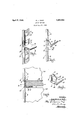
- Fig. 1 is a perspective view showing a shelf support connected with a vertical post on which it is mounted.
- Fig. 2 is a vertical section through the shelf support and post substantially on a plane coincident with the central longitudinal axis of the post and at right angles thereto, the shelf support being shown in a partially detached position.
- Fig. 3 is a perspective view of the shelf support and, j 69 Fig. 4 is a section similar to that, shown in 1929. Serial No. 373,238.
- the shelf support of which a number may be detachably connected with a post, is formed from a single piece of fiat metal and includes a vertical channel section 4 with outwardly ex-' tending flanges 5 as shown, shaped to embrace the outer sides of the channel 1 and flanges 2. At the upper end of the web of the channel section 4, said web is bent at right angles for a short distance, as indicated at 6, and then turned upwardly at right angles to form the terminal lip 7.
- the metal is continued and turned horizontally outward, as at 8, for a distance, bent back upon itself in a return bend 9, and continued in a lower side 10 which normally is located at a slight acute angle to the plane of the section 8.
- the end of the lower side 10 is notched at spaced apart points as shown forming an intermediate lip 11 which is bent in a downward direction and the underside of which is of a curved form and tapers upwardly to an edge at the upper side and at the free end of the lip 11 as shown.
- a shelf support of this character may be applied to the post by first inserting the lip 7 through any selected opening 3, tilting the support upwardly at an angle as shown'in Fig. '2, and then by movin the support do wnwardly the lip 11 enters t e opening next below that through which the lip 7 has been inserted, the under inclined and curved side 12 of the lip 11 riding against the lower edge of the opening 3 into. which said lip 11 is forced and snapping into place in said 0 ening with an accompanying springing o the under side 10 toward the upper section 8 of the shelf support, and a partial closing of the support attached v angular space between the two parts 8 and 10.
- a horizontal shelf 13 may be carried on and above the horizontal sections 8 of the shelf supports, the edges of the she lves coming against the webs of the pro ectlng channels 4 of the shelf supports and covering the same, the thickness of a shelf being equal to or greater than the height of said channel portion.
- shelf support is one which may be readily applied at difierent positions on the post therefor, the support being readily removed fiom the post and reattached at a different position.
- the attachment and detachment are simply and easily performed and after the attachment has once. been made the shelf support itself has an inherent capacity for guarding against accidental detachment.
- the construction of shelf support described may be readily manufactured at low cost and it has proved very practical and serviceable in use. The invention is described in the appended claims and is to be considered comprehensive of all forms of structure coming within their scope.
- An adjustable shelf support comprising, a vertical post having spaced apart slots located one above the other, and a shelf supporting member having a horizontally extending portion, a vertical'portion extending upwardly from an end of the horizontal portion and lying against a side of the post, a lip at the upper end of said vertical portion received in one of said slots, a member attached to the horizontally extending portion and adapted to engage the bottom of a lower slot in said post and means in the same plane as the said member adapted to abut the said p 2.
- An adjustable shelf support comprising, a vertical post having spaced apart slots located one above the other, and a shelf supporting member having a horizontal extending portion, a vertical portion extending up wardly from the inner end of the horizontal portion,a lip bent horizontally and then upwardly from the upper end of said vertical portion and received in one of said slots, said horizontal extending portion being bent back upon itself and having a second lip at its free end to enter a slot in said post below the slot in which the first lip is received, said second lip bearing against the lower edge of the slot whereby the first lip is held against the upper edge of the first mentioned slot.
- An adjustable shelf support comprising, a post having spaced apart slots located therealong, and a shelf supporting member having a portion extending outwardly at right angles to the axis of the said post, a portion extending from the inner end of the said out wardly extending portion along the post in one direction and parallel thereto, means at the end of said parallel portion passing through one of said slots, said outwardly extending portion being bent back upon itself, a lip integral with and extending from the free end of the return bent portion to enter another slot in said post, said integral lip bearing against the far edge of the slot whereby the said means at the end of the said parallel portion is held against the far edge of the slot in which it seats.
Landscapes
- Connection Of Plates (AREA)
Description
E. J. VOGT SHELF SUPPORT April 5, 1932.
Filed June 24. 1929 1110mm: in%e1bm-T 01. V0 T Patented Apr. 1932 ENGELBERT J. voezr, or GRAND MANUFACTURING oourm,
MICHIGAN 1 RAPIDS, MICHIGAN, ASSIGNOB TO KNAPE & VOGT OF GRAND RAPIDS, MICHIGAN, A CORPORATION OF SHELF SUPIORT -App1icat1on filed June 24,
This invention relates to a shelf support.
It is an object and purpose of the present invention to provide a simple and effective shelf support which may be adjustably attached to a vertical post, in any one of a large number of different positions, on a plurality of which supports a shelf may be carried, the
construction and an attachment of the shelf support being such that utilization of the maximum space between shelves for merchandise is had, a projecting part of the shelf support which has, in other forms of shelf supports, been in the way of the merchandlse or its containers, being located directly at the edges of the shelf so that no projection extends into the merchandise receiving space; and said projecting portions in the form of shelf support of the present invention serving a useful function rather than being disadvantageous in that the length of the shelf may be shortened.
Further objects of the invention are to provide a shelf support of the character noted, made from a single piece of metal very economically, and form the support so that it may detachably connect with a vertical post on which it is carried in a very novel and practical manner wherein an inherent spring characteristic of the shelf support, will serve to retain the same on' its post a ainst accidental disengagement, yet it can e engaged with or disengaged from the post easily and without the use of tools.
An understanding of the invention may be had from the following description taken in connection with the accompanying drawings in which,
Fig. 1 is a perspective view showing a shelf support connected with a vertical post on which it is mounted.
Fig. 2 is a vertical section through the shelf support and post substantially on a plane coincident with the central longitudinal axis of the post and at right angles thereto, the shelf support being shown in a partially detached position.
Fig. 3 is a perspective view of the shelf support and, j 69 Fig. 4 is a section similar to that, shown in 1929. Serial No. 373,238.
rectangular spaced apart openings 3 are made.
equally spaced from each other. The shelf support, of which a number may be detachably connected with a post, is formed from a single piece of fiat metal and includes a vertical channel section 4 with outwardly ex-' tending flanges 5 as shown, shaped to embrace the outer sides of the channel 1 and flanges 2. At the upper end of the web of the channel section 4, said web is bent at right angles for a short distance, as indicated at 6, and then turned upwardly at right angles to form the terminal lip 7.
At the lower end of the channel 4 and flanges 5 described, the metal is continued and turned horizontally outward, as at 8, for a distance, bent back upon itself in a return bend 9, and continued in a lower side 10 which normally is located at a slight acute angle to the plane of the section 8. The end of the lower side 10 is notched at spaced apart points as shown forming an intermediate lip 11 which is bent in a downward direction and the underside of which is of a curved form and tapers upwardly to an edge at the upper side and at the free end of the lip 11 as shown.
A shelf support of this character may be applied to the post by first inserting the lip 7 through any selected opening 3, tilting the support upwardly at an angle as shown'in Fig. '2, and then by movin the support do wnwardly the lip 11 enters t e opening next below that through which the lip 7 has been inserted, the under inclined and curved side 12 of the lip 11 riding against the lower edge of the opening 3 into. which said lip 11 is forced and snapping into place in said 0 ening with an accompanying springing o the under side 10 toward the upper section 8 of the shelf support, and a partial closing of the support attached v angular space between the two parts 8 and 10.
With supporting posts spaced apart from each other and with shelf supports attached to the posts and extending toward each other, a horizontal shelf 13 may be carried on and above the horizontal sections 8 of the shelf supports, the edges of the she lves coming against the webs of the pro ectlng channels 4 of the shelf supports and covering the same, the thickness of a shelf being equal to or greater than the height of said channel portion. This leaves all of the. space above a shelf free and unobstructed for the reception of merchandise cartons, such as 14, and the ends of the cartons may come directly against the out-er sides of the channels 1 of the posts, as shown in Fig. 4; and there is no place in the structure where the projecting portions of the channels 4: of the shelf supports interfere in anyway with positioning the merchandise cartons or boxes 1 L on or under the shelves. 1f the vertical portion 4 with its attached flanges 5 extended downwardly from the lower side 10 described, it would not be covered by the ends of the shelf 13 and would project into the space shown as occupied by the lower carton M in Fig. 4, not only making such space useless but interfering with the proper and orderly arrangement of the merchandise holding boxes or cartons.
This construction of shelf support is one which may be readily applied at difierent positions on the post therefor, the support being readily removed fiom the post and reattached at a different position. The attachment and detachment are simply and easily performed and after the attachment has once. been made the shelf support itself has an inherent capacity for guarding against accidental detachment. The construction of shelf support described may be readily manufactured at low cost and it has proved very practical and serviceable in use. The invention is described in the appended claims and is to be considered comprehensive of all forms of structure coming within their scope.
I claim:
1. An adjustable shelf support comprising, a vertical post having spaced apart slots located one above the other, and a shelf supporting member having a horizontally extending portion, a vertical'portion extending upwardly from an end of the horizontal portion and lying against a side of the post, a lip at the upper end of said vertical portion received in one of said slots, a member attached to the horizontally extending portion and adapted to engage the bottom of a lower slot in said post and means in the same plane as the said member adapted to abut the said p 2. An adjustable shelf support comprising, a vertical post having spaced apart slots located one above the other, and a shelf supporting member having a horizontal extending portion, a vertical portion extending up wardly from the inner end of the horizontal portion,a lip bent horizontally and then upwardly from the upper end of said vertical portion and received in one of said slots, said horizontal extending portion being bent back upon itself and having a second lip at its free end to enter a slot in said post below the slot in which the first lip is received, said second lip bearing against the lower edge of the slot whereby the first lip is held against the upper edge of the first mentioned slot.
3. An adjustable shelf support comprising, a post having spaced apart slots located therealong, and a shelf supporting member having a portion extending outwardly at right angles to the axis of the said post, a portion extending from the inner end of the said out wardly extending portion along the post in one direction and parallel thereto, means at the end of said parallel portion passing through one of said slots, said outwardly extending portion being bent back upon itself, a lip integral with and extending from the free end of the return bent portion to enter another slot in said post, said integral lip bearing against the far edge of the slot whereby the said means at the end of the said parallel portion is held against the far edge of the slot in which it seats.
In testimony whereof I afiix my signature ENGELBERT J. VOGT.
Priority Applications (1)
| Application Number | Priority Date | Filing Date | Title |
|---|---|---|---|
| US373238A US1852598A (en) | 1929-06-24 | 1929-06-24 | Shelf support |
Applications Claiming Priority (1)
| Application Number | Priority Date | Filing Date | Title |
|---|---|---|---|
| US373238A US1852598A (en) | 1929-06-24 | 1929-06-24 | Shelf support |
Publications (1)
| Publication Number | Publication Date |
|---|---|
| US1852598A true US1852598A (en) | 1932-04-05 |
Family
ID=23471548
Family Applications (1)
| Application Number | Title | Priority Date | Filing Date |
|---|---|---|---|
| US373238A Expired - Lifetime US1852598A (en) | 1929-06-24 | 1929-06-24 | Shelf support |
Country Status (1)
| Country | Link |
|---|---|
| US (1) | US1852598A (en) |
Cited By (20)
| Publication number | Priority date | Publication date | Assignee | Title |
|---|---|---|---|---|
| US2443517A (en) * | 1944-05-22 | 1948-06-15 | Acme Visible Records Inc | Sheet metal cabinet shelf support |
| US2489708A (en) * | 1945-01-12 | 1949-11-29 | United Metal Box Co Inc | Shelf support combination and cabinet |
| US2498623A (en) * | 1946-10-12 | 1950-02-21 | Illinois Tool Works | Detachable bracket |
| US2872145A (en) * | 1954-03-01 | 1959-02-03 | Abacus Inc | Support hanger for pin-up boards |
| US2876978A (en) * | 1956-04-04 | 1959-03-10 | Robinson Eliot | Support brackets |
| US2967625A (en) * | 1958-04-21 | 1961-01-10 | Don R Hoogenstyn | Shelving bracket |
| US3198342A (en) * | 1963-10-28 | 1965-08-03 | Thomas O Murray | Corrugated wall board |
| US3235218A (en) * | 1964-03-30 | 1966-02-15 | Harold E Graham | Article-display board |
| US4070803A (en) * | 1976-07-06 | 1978-01-31 | Gartung Clifford W | Supportive accessory units for modular wall panels |
| US4193649A (en) * | 1979-01-22 | 1980-03-18 | Zev Sharon | Anti-tilt bracket and clip assembly for adjustable drawers or similar articles |
| US4206955A (en) * | 1978-08-01 | 1980-06-10 | Cooper Jack M | Closet storage unit |
| US4539005A (en) * | 1983-10-24 | 1985-09-03 | Greenblatt Gordon M | Blood infusion apparatus and method |
| US4576302A (en) * | 1985-05-06 | 1986-03-18 | Smolik Robert A | Electrical receptacle box assembly |
| US4705244A (en) * | 1985-05-23 | 1987-11-10 | Toyota Jidosha Kabushiki Kaisha | Tube protecting device |
| US4711183A (en) * | 1986-08-01 | 1987-12-08 | Hirsh Company | Shelving assembly with drop-in shelf |
| US20100155354A1 (en) * | 2008-12-22 | 2010-06-24 | Krueger Daniel L | Shelf Support |
| US20180265290A1 (en) * | 2014-12-09 | 2018-09-20 | Swisslog Logistics, Inc. | Structure for Automated Pallet Storage and Retrieval |
| US10093449B2 (en) * | 2015-04-23 | 2018-10-09 | Crrc Meishan Co., Ltd. | Double-surface contact tray loading base |
| US12200894B2 (en) * | 2021-12-15 | 2025-01-14 | Hammond Manufacturing Company Limited | Rack rail support |
| US12471701B1 (en) * | 2025-01-03 | 2025-11-18 | Shenzhen Baite Youpin Supply Chain Co., Ltd. | Shelf |
-
1929
- 1929-06-24 US US373238A patent/US1852598A/en not_active Expired - Lifetime
Cited By (22)
| Publication number | Priority date | Publication date | Assignee | Title |
|---|---|---|---|---|
| US2443517A (en) * | 1944-05-22 | 1948-06-15 | Acme Visible Records Inc | Sheet metal cabinet shelf support |
| US2489708A (en) * | 1945-01-12 | 1949-11-29 | United Metal Box Co Inc | Shelf support combination and cabinet |
| US2498623A (en) * | 1946-10-12 | 1950-02-21 | Illinois Tool Works | Detachable bracket |
| US2872145A (en) * | 1954-03-01 | 1959-02-03 | Abacus Inc | Support hanger for pin-up boards |
| US2876978A (en) * | 1956-04-04 | 1959-03-10 | Robinson Eliot | Support brackets |
| US2967625A (en) * | 1958-04-21 | 1961-01-10 | Don R Hoogenstyn | Shelving bracket |
| US3198342A (en) * | 1963-10-28 | 1965-08-03 | Thomas O Murray | Corrugated wall board |
| US3235218A (en) * | 1964-03-30 | 1966-02-15 | Harold E Graham | Article-display board |
| US4070803A (en) * | 1976-07-06 | 1978-01-31 | Gartung Clifford W | Supportive accessory units for modular wall panels |
| US4206955A (en) * | 1978-08-01 | 1980-06-10 | Cooper Jack M | Closet storage unit |
| US4193649A (en) * | 1979-01-22 | 1980-03-18 | Zev Sharon | Anti-tilt bracket and clip assembly for adjustable drawers or similar articles |
| US4539005A (en) * | 1983-10-24 | 1985-09-03 | Greenblatt Gordon M | Blood infusion apparatus and method |
| US4576302A (en) * | 1985-05-06 | 1986-03-18 | Smolik Robert A | Electrical receptacle box assembly |
| US4705244A (en) * | 1985-05-23 | 1987-11-10 | Toyota Jidosha Kabushiki Kaisha | Tube protecting device |
| US4711183A (en) * | 1986-08-01 | 1987-12-08 | Hirsh Company | Shelving assembly with drop-in shelf |
| US20100155354A1 (en) * | 2008-12-22 | 2010-06-24 | Krueger Daniel L | Shelf Support |
| US8157230B2 (en) * | 2008-12-22 | 2012-04-17 | Knape & Vogt Manufacturing Company | Shelf support |
| US20180265290A1 (en) * | 2014-12-09 | 2018-09-20 | Swisslog Logistics, Inc. | Structure for Automated Pallet Storage and Retrieval |
| US11084622B2 (en) * | 2014-12-09 | 2021-08-10 | Swisslog Logistics, Inc. | Structure for automated pallet storage and retrieval |
| US10093449B2 (en) * | 2015-04-23 | 2018-10-09 | Crrc Meishan Co., Ltd. | Double-surface contact tray loading base |
| US12200894B2 (en) * | 2021-12-15 | 2025-01-14 | Hammond Manufacturing Company Limited | Rack rail support |
| US12471701B1 (en) * | 2025-01-03 | 2025-11-18 | Shenzhen Baite Youpin Supply Chain Co., Ltd. | Shelf |
Similar Documents
| Publication | Publication Date | Title |
|---|---|---|
| US1852598A (en) | Shelf support | |
| US9228347B2 (en) | Torsion spring metal ceiling system and hardware | |
| US1853018A (en) | Adjustable shelf bracket | |
| US3138283A (en) | Filing device | |
| US3163287A (en) | Trays | |
| US2721632A (en) | Partition structure for articles of furniture | |
| US4055284A (en) | Vehicle article carrier | |
| US2528807A (en) | Shelving | |
| US2238238A (en) | Molding fastener | |
| US2070055A (en) | Shelf attachment | |
| US2181966A (en) | Fastening device | |
| US3212754A (en) | Interlocking structure for fences or the like | |
| US1889218A (en) | Combination rack and pan | |
| US2532023A (en) | Luminaire for elongate tubular lamps comprising telescoped extensible sections | |
| US1849659A (en) | Support and spacer for stacking boxes | |
| US2483769A (en) | Counter bin construction | |
| US2147086A (en) | Display package and stand | |
| US4446669A (en) | End channel member for space dividing system panel | |
| US1770942A (en) | Adjustable partition support | |
| US2522477A (en) | Rack for smoking pipes | |
| US1609355A (en) | Metal shelving | |
| US1875318A (en) | of brooklyn | |
| US1619099A (en) | Oil-can holder | |
| US2776792A (en) | Device for storing frozen food packages | |
| US3366357A (en) | Furniture leg mounting |