US1852588A - Web cutting and folding mechanism - Google Patents
Web cutting and folding mechanism Download PDFInfo
- Publication number
- US1852588A US1852588A US435577A US43557730A US1852588A US 1852588 A US1852588 A US 1852588A US 435577 A US435577 A US 435577A US 43557730 A US43557730 A US 43557730A US 1852588 A US1852588 A US 1852588A
- Authority
- US
- United States
- Prior art keywords
- pin
- pins
- shaft
- secured
- cylinder
- Prior art date
- Legal status (The legal status is an assumption and is not a legal conclusion. Google has not performed a legal analysis and makes no representation as to the accuracy of the status listed.)
- Expired - Lifetime
Links
- 230000007246 mechanism Effects 0.000 title description 28
- 238000010276 construction Methods 0.000 description 5
- 239000011435 rock Substances 0.000 description 4
- 230000002093 peripheral effect Effects 0.000 description 1
- 238000009877 rendering Methods 0.000 description 1
Images

Classifications
-
- B—PERFORMING OPERATIONS; TRANSPORTING
- B65—CONVEYING; PACKING; STORING; HANDLING THIN OR FILAMENTARY MATERIAL
- B65H—HANDLING THIN OR FILAMENTARY MATERIAL, e.g. SHEETS, WEBS, CABLES
- B65H45/00—Folding thin material
- B65H45/12—Folding articles or webs with application of pressure to define or form crease lines
- B65H45/16—Rotary folders
- B65H45/161—Flying tuck folders
-
- B—PERFORMING OPERATIONS; TRANSPORTING
- B65—CONVEYING; PACKING; STORING; HANDLING THIN OR FILAMENTARY MATERIAL
- B65H—HANDLING THIN OR FILAMENTARY MATERIAL, e.g. SHEETS, WEBS, CABLES
- B65H45/00—Folding thin material
- B65H45/12—Folding articles or webs with application of pressure to define or form crease lines
- B65H45/16—Rotary folders
- B65H45/162—Rotary folders with folding jaw cylinders
- B65H45/168—Rotary folders with folding jaw cylinders having changeable mode of operation
Definitions
- This invention relates to cutting and fold ing mechanism for rotary web printing machines such as are used for printing newspapers and similar products.
- the printed webs are associated and then cut into sheets by passing themv between a pair of cylinders, one of which carries a cutting knife and the other a suitable abutment for the knife.
- the sheets thus out are held on one of the cylinders by means of pins that project from the surface of the cylinder and which can be retracted when the sheets are to be removed from the cylinder and passed on to the folding mechanism or the delivery.
- An object of the invention is to prov1de a sheet holding pin mechanism for cutting and collecting cylinders in which the pins may be easily removed and replaced. 7
- Another object of the invention is to provide a sheet holding pin mechanism in which a rugged form of pin may be used, and that will not have any delicate parts.
- Another object of the invention is to provide a sheet holding pin mechanism that may quickly beladjusted to provide for delivering either. a'collected or a non collected product.
- Another object of the invention is to provide asheet holding :pin mechanism in which the reciprocating parts may be very light in Weight.
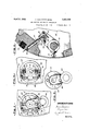
- Figure 1 is a side view partly brokenaway and partly in section showing a folding cylinder equipped with the pin operating mechanism that is the subject of the invention
- Figure 2 is a fragmentary sectional view of the folding cylinder shown in Figure 1 as seen on the line AA in the direction of arrow 2;
- Figure 3 is a fragmentary view of one end of the folding cylinder shown in Figure 1 showing the arm and roller that co-act with a cam to drive the pin operatingv mechanism, the view being shown in the direction of arrow 3 of Figure 1; V
- Figure 1 is a view similar to FigureBshoW- ing particularly the mechanism foradjusting the operating arm with respect to the shaft that it drives;
- Figure 5 is a detail view of the cam roller arm.
- 11 indicates a folding cylinder having end plates 12 and, 12.
- a bearing bushing 13 having a flange 13 is secured to the end plate 12 of the cylinder,
- rock shaft by means of the screws 14 and provides a' bearing fora rock shaft 15, the opposite end of which is rotatably supported in the end wall 12.
- rock shaft by setscrews 17 and are preferably formed with forked ends having parallel faces indicated at 18.
- Sliding blocks 19 are fitted to engage the faces 18:and carry a pin supporting rod 21, to which pin holders 22 are secured by means of set screws 23.
- Sheet engaging pins 24 are screw threaded into the pin holders 22, and preferably engage the pin supporting rod 21. These pins are formed with a squared portion at 2A so they may be engaged by a socket wrench.
- the sheet engaging pins are fitted to slide in guides or sleeves 25 secured to the wall of the cylinder 11.
- One end of the shaft 15 is formed with-a l flange 26 and has a reduced portion 27.
- the flange 26 has elongated openings 28, 29 and 31.
- a cam roller arm 32 is provided with a hub 3, having a bore 34 which fits over the end portion 27 of the shaft 15 and serves to position the hub of the cam roller arm in concentric alignment with the shaft 15.
- the stud 35 projects into the opening 31 and is engaged by the ends of the screws 38 and 39 that are screw threaded into the flange 26, means being thus provided to rotate the cam roller arm to a limited extent with respect to the flange 26 and to lock it in the desired position.
- Holes 36 and 37 are tapped into the hub 33, and bolts 41 and 42 pass through the openings 28 and 29 of the flange 26 and are screwed into the holes 36 and 37 respectively, thus providing means for locking the flange 26 and the hub 33 together.
- the extremity of the cam roller arm is fitted with a suitable pivot which rotatably supports the cam roller 43.
- a stop 44 is secured to the cylinder wall 12 and furnishes an abutment fora plate 45 that is secured to the shaft 15 thus serving to limit the rotation of the shaft in one direction.
- a rubber abutment for the cutting knife is shown at 46 and is adapted to engage the usual form of cutting blade to sever the web that passes through the machine into sheets, the cut ends of which are held by the sheet engaging pins until they are folded off the cylinder by the operation of a folding blade of well known type.
- Bridges 47 are secured to the cylinder 11 so their outer surfaces conform with its periphery and serve to support the web, and the openings between the bridges provide access to the pin operating mechanism.
- the mechanism may be operated by a cam, the use of which is common in this class of work, the cam, which is not shown, being engaged by the roller 43 which acts to rock the shaft 15 in one direction to extend the pins 24 to the position shown in Figure 2, and in the opposite direction to withdraw them so their points are within the periphery of the folding cylinder.
- the blocks 19 are arranged to slide between the parallel faces 18 and thus permit the pins 24 to maintain perfect alignment with the sleeves 25 when the arms 16 are moved by the rotation of the rockshaft.
- the products are sometimes delivered uncollected and at other times collected.
- the collecting cylinders are arranged so their peripheral length is twice the length of the product.-
- both sets of pin operating mechanisms are used, but when a collected product is to be delivered, one set of pins rendered inoperative and all of the products are handled by the other set.
- Means for conveniently rendering one set of pins inoper- 1 ative is provided by the adjusting screws 38 and 39, for it will be understood that by changing the relation of the cam roller arm to the pin operating mechanism that the pins 24 may be made to oscillate entirely within the sleeves 25, and under these conditions their points will not emerge from the cylinder. Also by shifting the cam roller arm in the opposite direction, the pins may be made to protrude beyond the cylinder sufficiently to enable the squared portion to be engaged by a wrench.
- a rocking shaft having a roller adapted to engage a cam, a pin supporting rod slidable substantially radially porting rod held in the blocks, pins secured to the rod, and guides in Which the pins are fitted to slide.
- pin operating arms blocks fitted to slide in the arms, a pin supporting rod secured to the blocks, pin-s secured to the rod, guides in which the pins are fitted to slide, and means to adjust the position of the pin operating arms relative to the position of the shaft rocking means.
- a sheet holding pin mechanism of the class described a plurality of sheet holding pins, guides for the pins, a pin support- -i ing rod to which the pins are secured, and
- a plurality of pins each having one end point- I ed to engage a sheet and threaded on the other end, guides in which the pins are fitted to slide, a pin supporting rod carrying pin holders into Which the pins are screwed, and means for moving the rod to protrude and retract the pins.
Landscapes
- Folding Of Thin Sheet-Like Materials, Special Discharging Devices, And Others (AREA)
Description
April 5, 1932.
F'IG.I.
F. SCHIPPERS ET AL 2,588
WEB CUTTING AND FOLDING MECHANISM Filed March 13, 1930 2 Sheets-Sheet 1 u jwni A ril 5, 1932. F. SCHIPPERS ET AL WEB CUTTING AND FOLDING MECHANISM 2 Sheets-Sheet 2 Filed March 13, 1930 INVENTORS Patented Apr. 5, 1932 UNITED A STATES PATENT OFFICE FRANK SCHIPPERS AND AUGUST WEIS, OF BROOKLYN, NEW YORK, ASSIGNORS TO Rn'HOE & 00., I-NC., OF NEW YORK, N. Y., A CORPORATION OF NEW YORK WEB CUTTING AND FOLDING MECHANISM Application filed March 13, 1930. Serial No. 435,577.
This invention relates to cutting and fold ing mechanism for rotary web printing machines such as are used for printing newspapers and similar products.
In this class of work, the printed webs are associated and then cut into sheets by passing themv between a pair of cylinders, one of which carries a cutting knife and the other a suitable abutment for the knife. The sheets thus out are held on one of the cylinders by means of pins that project from the surface of the cylinder and which can be retracted when the sheets are to be removed from the cylinder and passed on to the folding mechanism or the delivery.
Various'sheet holding pin mechanisms and various means for supporting and operating the pins have heretofore been used, but this invention provides an improved mechanism, the advantages of which will be hereinafter disclosed.
An object of the invention is to prov1de a sheet holding pin mechanism for cutting and collecting cylinders in which the pins may be easily removed and replaced. 7
Another object of the invention is to provide a sheet holding pin mechanism in which a rugged form of pin may be used, and that will not have any delicate parts.
Another object of the invention is to provide a sheet holding pin mechanism that may quickly beladjusted to provide for delivering either. a'collected or a non collected product.
Another object of the invention is to provide asheet holding :pin mechanism in which the reciprocating parts may be very light in Weight.
It is also an object of the invention to provide a sheet holding pin mechanism of generally improved construction, whereby the device will be simple, durable and inexpensive in construction, as well as convenient, practical,serviceable andefficient in its use.
With the foregoing and other objects in view, which will appear as the description proceeds, the inventionresides in the combination andarrangement of parts, and in the details of construction hereinafter described and claimed, it being understood that various changes in the precise embodiment of the invention herein disclosed may be made within the scope of what is claimed without departing from the spirit of the invention.
The preferred embodiment of the invention is illustrated in the accompanying-drawlngs, wherein:
Figure 1 is a side view partly brokenaway and partly in section showing a folding cylinder equipped with the pin operating mechanism that is the subject of the invention;
Figure 2 is a fragmentary sectional view of the folding cylinder shown in Figure 1 as seen on the line AA in the direction of arrow 2;
Figure 3 is a fragmentary view of one end of the folding cylinder shown in Figure 1 showing the arm and roller that co-act with a cam to drive the pin operatingv mechanism, the view being shown in the direction of arrow 3 of Figure 1; V
Figure 1 is a view similar to FigureBshoW- ing particularly the mechanism foradjusting the operating arm with respect to the shaft that it drives; and
Figure 5 is a detail view of the cam roller arm.
In the drawings, 11 indicates a folding cylinder having end plates 12 and, 12. A bearing bushing 13 having a flange 13 is secured to the end plate 12 of the cylinder,
by means of the screws 14 and provides a' bearing fora rock shaft 15, the opposite end of which is rotatably supported in the end wall 12. rock shaft by setscrews 17 and are preferably formed with forked ends having parallel faces indicated at 18. Sliding blocks 19 are fitted to engage the faces 18:and carry a pin supporting rod 21, to which pin holders 22 are secured by means of set screws 23. Sheet engaging pins 24 are screw threaded into the pin holders 22, and preferably engage the pin supporting rod 21. These pins are formed with a squared portion at 2A so they may be engaged by a socket wrench. The sheet engaging pins are fitted to slide in guides or sleeves 25 secured to the wall of the cylinder 11.
A rubber abutment for the cutting knife is shown at 46 and is adapted to engage the usual form of cutting blade to sever the web that passes through the machine into sheets, the cut ends of which are held by the sheet engaging pins until they are folded off the cylinder by the operation of a folding blade of well known type.
It will be understood that the mechanism may be operated by a cam, the use of which is common in this class of work, the cam, which is not shown, being engaged by the roller 43 which acts to rock the shaft 15 in one direction to extend the pins 24 to the position shown in Figure 2, and in the opposite direction to withdraw them so their points are within the periphery of the folding cylinder. The blocks 19 are arranged to slide between the parallel faces 18 and thus permit the pins 24 to maintain perfect alignment with the sleeves 25 when the arms 16 are moved by the rotation of the rockshaft.
In comparing this mechanism with that heretofore used, it is found that the reciprocating parts, although of relatively rugged construction are considerably lighter in weight. With the previously known arrangement, the pin points are made relatively short and are threaded into a pin holder which slides in the sleeves. It has been found that the threaded portions of these pins very frequently break ofl inside the pin holder, and it is consequently necessary to discard the holder which is a relatively expensive part. With the mechanism shown herein, the pin point is integral with the rod that slides in the sleeves 25, and in consequence, breakage of a pin is less likely to occur and when it does nothing more than the pin need be replaced.
On printing machines in which this equipment is used, the products are sometimes delivered uncollected and at other times collected. In order to deliver the products in either manner, the collecting cylinders are arranged so their peripheral length is twice the length of the product.- When delivering an uncollected product both sets of pin operating mechanisms are used, but when a collected product is to be delivered, one set of pins rendered inoperative and all of the products are handled by the other set. Means for conveniently rendering one set of pins inoper- 1 ative is provided by the adjusting screws 38 and 39, for it will be understood that by changing the relation of the cam roller arm to the pin operating mechanism that the pins 24 may be made to oscillate entirely within the sleeves 25, and under these conditions their points will not emerge from the cylinder. Also by shifting the cam roller arm in the opposite direction, the pins may be made to protrude beyond the cylinder sufficiently to enable the squared portion to be engaged by a wrench.
With the construction heretofore used, when it was necessary to replace a pin holder because of breakage of the pin or for any 3* 2. In a sheet holding pin mechanism of the class described, pins slidable in guides, a pin operating rod secured to the pins, a rocking shaft operatably connected to the rod, and means to rock the shaft.
3. In a sheet holding pin mechanism of 3% the class described, a rocking shaft, pin operating arms on the shaft, a pin supporting rod slidable substantially radially with respect to the arms, pin holders secured to the rod, and
pins secured to the pin holders.
4. In a sheet holding pin mechanism, a rocking shaft, pin operating arms on the shaft, a cam roller arm on the shaft having a roller adapted to engage a cam, a pin supporting rod slidable substantially radially porting rod held in the blocks, pins secured to the rod, and guides in Which the pins are fitted to slide.
6. In a sheet holding. pin mechanism, a rocking shaft, means for rocking the shaft,
; pin operating arms, blocks fitted to slide in the arms, a pin supporting rod secured to the blocks, pin-s secured to the rod, guides in which the pins are fitted to slide, and means to adjust the position of the pin operating arms relative to the position of the shaft rocking means.
7. In a sheet holding pin mechanism of the class described, a plurality of sheet holding pins, guides for the pins, a pin support- -i ing rod to which the pins are secured, and
means for moving the rod to extend and retract the pins.
8. In a sheet holding in mechanism, a plurality of pins each having one end point- I ed to engage a sheet and threaded on the other end, guides in which the pins are fitted to slide, a pin supporting rod carrying pin holders into Which the pins are screwed, and means for moving the rod to protrude and retract the pins.
In testimony whereof, We affix our signatures.
FRANK SCHIPPERS. AUGUST WEIS.
Priority Applications (1)
| Application Number | Priority Date | Filing Date | Title |
|---|---|---|---|
| US435577A US1852588A (en) | 1930-03-13 | 1930-03-13 | Web cutting and folding mechanism |
Applications Claiming Priority (1)
| Application Number | Priority Date | Filing Date | Title |
|---|---|---|---|
| US435577A US1852588A (en) | 1930-03-13 | 1930-03-13 | Web cutting and folding mechanism |
Publications (1)
| Publication Number | Publication Date |
|---|---|
| US1852588A true US1852588A (en) | 1932-04-05 |
Family
ID=23728950
Family Applications (1)
| Application Number | Title | Priority Date | Filing Date |
|---|---|---|---|
| US435577A Expired - Lifetime US1852588A (en) | 1930-03-13 | 1930-03-13 | Web cutting and folding mechanism |
Country Status (1)
| Country | Link |
|---|---|
| US (1) | US1852588A (en) |
-
1930
- 1930-03-13 US US435577A patent/US1852588A/en not_active Expired - Lifetime
Similar Documents
| Publication | Publication Date | Title |
|---|---|---|
| US5417642A (en) | Folding jaw cylinder | |
| US3034429A (en) | Printing press | |
| US2335431A (en) | Sheet collecting and folding mechanism for printing presses | |
| US1852588A (en) | Web cutting and folding mechanism | |
| US2031780A (en) | Rotary cutting and folding mechanism for printing machines | |
| GB536884A (en) | Improvements in web roll supports | |
| US2395950A (en) | Slitter mechanism for printing presses | |
| US2086476A (en) | Web cutting mechanism | |
| US1797448A (en) | Cutting mechanism | |
| US1798910A (en) | Sheet cutting and handling mechanism | |
| US2305536A (en) | Slitter and rewinder | |
| US2264707A (en) | Folder | |
| US1977566A (en) | Slitting mechanism for printing machines | |
| US3275254A (en) | Slitter | |
| US2746748A (en) | Movable nipping roller delivery for a printing machine | |
| US1752426A (en) | Folding mechanism | |
| US222455A (en) | Improvement in printing and folding machines | |
| US1584360A (en) | Folding mechanism | |
| US1739398A (en) | jordhoy | |
| US1870545A (en) | Web feeding and slitting mechanism | |
| US1826601A (en) | Sheet cutting, collecting, and folding mechanism | |
| US2017619A (en) | Folding device for rotary printing machines | |
| US863007A (en) | Cutter mechanism for sheet-folding and other machines. | |
| US1993652A (en) | Paper folding machine | |
| US2110901A (en) | Web cutting mechanism for printing machines |