US1852587A - Combination desk and pocket seal - Google Patents
Combination desk and pocket seal Download PDFInfo
- Publication number
- US1852587A US1852587A US558712A US55871231A US1852587A US 1852587 A US1852587 A US 1852587A US 558712 A US558712 A US 558712A US 55871231 A US55871231 A US 55871231A US 1852587 A US1852587 A US 1852587A
- Authority
- US
- United States
- Prior art keywords
- jaw
- bosses
- stem
- frame
- cam
- Prior art date
- Legal status (The legal status is an assumption and is not a legal conclusion. Google has not performed a legal analysis and makes no representation as to the accuracy of the status listed.)
- Expired - Lifetime
Links
- 230000037431 insertion Effects 0.000 description 5
- 238000003780 insertion Methods 0.000 description 5
- 239000000463 material Substances 0.000 description 4
- 238000010276 construction Methods 0.000 description 3
- 238000006073 displacement reaction Methods 0.000 description 3
- 238000005452 bending Methods 0.000 description 2
- 230000005484 gravity Effects 0.000 description 2
- OKTJSMMVPCPJKN-UHFFFAOYSA-N Carbon Chemical compound [C] OKTJSMMVPCPJKN-UHFFFAOYSA-N 0.000 description 1
- 230000004075 alteration Effects 0.000 description 1
- 230000002596 correlated effect Effects 0.000 description 1
- 239000000428 dust Substances 0.000 description 1
- 230000000694 effects Effects 0.000 description 1
- 239000011796 hollow space material Substances 0.000 description 1
- 230000002787 reinforcement Effects 0.000 description 1
- 230000003014 reinforcing effect Effects 0.000 description 1
Images
Classifications
-
- B—PERFORMING OPERATIONS; TRANSPORTING
- B41—PRINTING; LINING MACHINES; TYPEWRITERS; STAMPS
- B41K—STAMPS; STAMPING OR NUMBERING APPARATUS OR DEVICES
- B41K3/00—Apparatus for stamping articles having integral means for supporting the articles to be stamped
- B41K3/36—Apparatus for stamping articles having integral means for supporting the articles to be stamped with means for deforming or punching the copy matter
-
- B—PERFORMING OPERATIONS; TRANSPORTING
- B44—DECORATIVE ARTS
- B44B—MACHINES, APPARATUS OR TOOLS FOR ARTISTIC WORK, e.g. FOR SCULPTURING, GUILLOCHING, CARVING, BRANDING, INLAYING
- B44B5/00—Machines or apparatus for embossing decorations or marks, e.g. embossing coins
- B44B5/0085—Portable apparatus for manual operation
Definitions
- This invention relates to new and useful improvements in a combination desk and pocket seal.
- the invention has for an object the con struction of a seal of the class mentioned which is characterized by a substantially U- shaped frame turned on its side so that one arm constitutes the bottom of the (ll-W106 and allows the insertion of paper or other ma terial to be impressed between the arms of the frame, eliminating the necessity of bending the paper or material as is customary in present day seals.
- a still further object of this invention is to reinforce the U-shaped frame with ribs arranged to simultaneously provide a hollow space into which a handle for operating the movable jaw may be disposed.
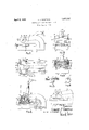
- FIG. 1 is a side elevational view of a device constructed according to this invention.
- Fig. 2 is an end elevational view of Fig. 1 looking from the left hand side.
- Fig. 3 is a plan view of Fig. 1.
- Fig. 4 is a transverse enlarged sectional view taken on the line 44 of Fig. 2.
- Fig. 5 is a side elevational view of the Cam used for actuating the jaw of the device.
- Fig. 6 is an end elevational view of Fig. 5.
- Fig. 7 is a fragmentary sectional view taken on the line 7 7 of Fig. 3.
- Fig. 8 is a View similar to a portion of Fig. 1 but illustrating the device with one of the bushings which supports the device removed.
- the stem 17 is formed with a transverse opening 21 in which a cam 22 operates.
- the opening 21 is elongated along the horizontal cam 22 located well towards the rear of the opening 21 so as to cause the aw 16 to assume the slightly inclined position indicated by the angle C.
- the cam 22 is integral with stems 23 projecting from both sides. These stems rotatively engage within bushings 24: extended through the bosses 13. Flanges 25 on the outer ends of the bushings 2 1 limit the amount of insertion of the bushings within the bosses. Screws 26 threadedly engage within the ends of the stems 23 and serve to prevent displacement of the bushings 2 1.
- the cam 22 is of circular form and of a diameter slightly smaller than the diameter within the bosses 13 which accommodate the bushings 2d. Consequently, it is possible to insert the cam in place by passing it through one of the openings in the bosses. Once located between the bosses, it may be moved to a position in which the stems 23 are coaxial within the openings in
- the stem 17 from the jaw is formed with an opening 26' extended from the top to the rear side.
- a handle 15 has a peg portion 28 engaged through an aperture in the cam 22. This handle projects from the opening 26.
- Fig. 4 it is shown in a raised position wherein the jaw 16 is correspondingly raised. In the other figures the handle is shown lowered and the jaw correspondingly lowered.
- a set screw 29 may be engaged through the cam 22 and against the peg portion 28 of the handle to lock the handle in place.
- over-all length between the extremities of the stems 23 is slightly greater than the location of the outer faces of the bushings 24 so that the screws 27 may rest against the ends of the stems 23 and in this manner prevent possible binding.
- Fig. 1 A document or other material upon which the seal is to be impressed may be engaged between the seal elements 20. This document may be inserted to any depth limited by the bar of the U- sh'aped frame. The arms of the U-shaped frame may be of any length to accommodate for special needs in the insertion of paper or other material to be impressed.
- the cam 22 will move downwards so as to lower the jaw 16.
- jaw 16 will first engage with one side against the paper and as the handle continues to be moved to the lowered position the jaw will be moved down flat and form the impression.
- a minor feature of the invention is the arrangement of the parts so that they may be conveniently assembled. It should be noted that the d vice may be taken apart by first removing the bridge 18. This bridge covers an opening 17 in the stem portion 17 of the movable jaw. A screw driver may be inserted through this opening and the set screw 29 loosened so that the handle 15 can be withdrawn. Thereafter, the bushings 2a and the cam 22 should be moved to a position wherein they may be passed through one of the ap ertures in which the bushings 2 1 were positioned.
- the moveable jaw 16 is automatically self-closing.
- the opening 26 limits the raising of the handle 15 to the vertical position, which position itcannot maintain because of the offset stems 23 of the cam 22'. Consequently, it will fall due to gravity to the position shown in Fig. 1 which is the closed position.
- the closing of the seal elements eliminates dust from settling into the seal and reducing its effect.
- a combination desk and pocket seal comprising a frame of substantially U-shape and turn-ed on one side so that one rin con-- stitutes the bottom thereof, the top arm of said framebeing formed with spaced bosses. a jaw between the arms of the frame and having a stem extending between said bosses, said stem having a transverse opening seal elements on the opposing faces of said jaw and the bottom arm, a cam within said transverse opening in the stem of said jaw and having stems journaled in said bosses, and a handle engaging through an opening in the stem of said jaw and into said cam.
- a combination desk and pocket seal comprising a frame of substantially U-shape and turned on one side so that one arm constitutes the bottom thereof, the top arm of said frame being formed with spaced bosses,
- said frame having a stem extending between said bosses, said stem having a transverse opening seal elements on the opposing faces of said jaw and the bottom arm, a cam within said transverse opening in the stem of said jaw and having stems journaled in said bosses, and a handle engaging through an opening in the stem of said jaw and into said cam, said frame being reinforced by ribs extending from the bosses on the top arm around the bend of the frame.
- a combination desk and pocket seal comprising a frame of substantially U-shape and turned on one side so that one arm constitutes the bottom thereof, the top arm of said frame being formed with spaced bosses, a jaw between the arms of the frame and having a stem extending between said bosses, said stem having a transverse opening seal elements on the opposing faces of said jaw and the bottom arm, a cam within said transverse opening in the stem of said jaw and having stems j ournaled in said bosses, and a handle engaging through an opening in the stem of said aw and into said cam, said frame be ing reinforced by ribs extending from the bosses on the top arm around the bend of the frame, and said handle being capable of assuming a position between said reinforcing ribs.
- a combination desk and pocket seal comprising a frame substantially U-shape and turned on one side so that one arm constitutes the bottom thereof, the top arm of said frame being formed with spaced bosses, a jaw between the arms of the frame and having astem extending between said bosses, seal elements on the opposing faces of said jaw and the bottom arm, a cam within a transverse opening in the stem of said jaw and having stems journaled in said bosses, and a handle engaging through an opening in the stem of said jaw and into said cam, a bridge being attached between the front faces of said bosses and serving to slidably hold the stem of said jaw, said brid e also covering an opening in the stem of said jaw, providing for the insertion of the screw driver to reach a set screw engaged through said cam and abutting the handle for maintaining the latter element in place.
- a combination desk and pocket seal comprising a frame of substantially U-shape and turned on one side so that one arm constitutes the bottom thereof, the top arm of said frame being formed with spaced bosses, a jaw between the arms of the frame and having a stem extending between said bosses, seal elements on the opposing faces of said jaw and the bottom arm, a.
- a combination desk and pocket seal comprising a frame of substantially U-shape and turned on one side so that one arm constitutes the bottom thereof, the top arm of said frame being formed with spaced bosses, a jaw between the arms of the frame and having a stem extending between said bosses, seal elements on the opposing faces of said jaw and the bottom arm, a cam within a transverse opening in the stem of said jaw and having stems journaled in said bosses, and a handle engaging through an opening in the stem of said jaw and into said-cam, a bridge being attached between the front faces of said bosses and serving to slidably hold the stem of said jaw, said bridge and the portion of said upper arm which en ages the stem of said jaw being at a slight angle to the vertical so that the aw may assume a slightly in clined position, said cam being offset from the center of said jaw in a raised position of the jaw so as to hold the aw at an inclination as permitted by the inclined surfaces.
- a combination desk and pocket seal comprising a frame of substantially U-shape and turned on one side so that one arm constitutes the bottom thereof, the top arm of said frame being formed with spaced bosses, a jaw between the arms of the frame and having a stem extending between said bosses, seal elements on the opposing faces of said jaw and the bottom arm, a cam within a transverse opening in the stem of said jaw and having stems journaled in said bosses, and a handle engaging through an opening in the stem of said aw and into said cam,-bushings being engaged within said bosses for the proper supporting of the stem from said cam.
- a combination desk and pocket seal comprising a frame of substantially U-shape and turned on one side so that one arm constitutes the bottom thereof, the top arm of said frame being formed with spaced bosses, a jaw between the arms of the frame and having a stem extending between said bosses, seal elements on the opposing faces of said jaw and the bottom arm, a cam within a transverse opening in the stem of said jaw and having stems journaled in said bosses, and a handle engaging through an opening in the stem of said jaw and into said cam, the bosses of said frame being formed with circular openingsof a size to allow the insertion of the cam there through to assume aposition between the bosses, and bushings being engaged within the openings in thebosses for supporting the stems fromthe cam.
- a combination desk and pocket seal comprising a frame of substantially U-shape and turned on one side so that one arm conunder the force of gravity for the purpose of stitutes the bottom thereof, the top arm of closing said body.
- said frame being formed with spaced bosses, a jaw between the arms of the frame and having a stem extending between said bosses, seal elements on the opposing faces of said jaw and the bottom arm, a cam within a transverse opening in the stem of said jaw and and having stems journaled in said bosses, and a handle engaging through an opening in the stem of said aw and into said cam, said handle having a peg portion engaging through an aperture in said cam.
- a combination desk and pocket seal comprising a frame of substantially U-shape and turned on one side so that one arm constitutes the bottom thereof, the top arm of said frame being formed with spaced bosses, a jaw between the arms of the frame and having a stem extending between said bosses, seal elements on the opposing faces of said jaw and the bottom arm, a cam within a transverse opening in the stem of said jaw and having stems journaled in said bosses, and a handle engaging through an opening in the stem of said jaw and into said cam, said handle having a peg portion engaging through an aperture in said cam, and a set screw within the cam abutting said peg portion for securely holding the handle in place.
- a combination desk and pocket seal comprising a frame of substantially U-shape and turned on one side so that one arm constitutes the bottom thereof, the top arm of said frame being formed with spaced bosses, a jaw between the arms of the frame and having a stem extending between said bosses, seal elements on the opposing faces of said jaw and the bottom arm, a cam within a transverse opening in the stem of said jaw and havin stems journaled in said bosses, and a handle engaging through an opening in the stem of said jaw and into said cam, bushings being mounted within said bosses and the stems from said cam extending through the bushings and projecting slightly from the faces thereof, and screws engaging within the free ends of the stems of the cam so as to prevent displacement of the bushings.
- a combination desk and pocket seal comprising a frame of substantially U-shape and turned on one side so that one arm constitutes the bottom thereof, the top arm of said frame being formed with spaced bosses, a jaw between the arms of the frame and having astem extending between said bosses, seal elements on the opposing faces of said jaw and the bottom arm, a cam within a transverse opening in the stem of saidjaw and having stems journaled in said bosses, and a handle engaging through an opening in the stem of said jaw and into said cam, said opening in the stem limiting the handle to a raised vertical position wherein it tends to fall down In testimony whereof I aflix my signature.
Landscapes
- Sheet Holders (AREA)
Description
April 5, 1932. EN], ggg- 1,852,587
COMBINATION DESK AND POCKET SEAL Filed Aug. 22, 1931 I I 1 F\G. 8
INVENTOR EDWARD J RAN-Tam FmA BY ms ATTORNEY MW 7 Patented Apr. 5, 1932 UNiTE EDWARD J. RANTSCI-I, OF HOLLIS, NEW YORK, ASSIGNOR TO EXCELSIOR STATIONERY COMPANY, OF NEi/V YORK, N. Y.
COMBINATION DESK AND ROCKET SEAL Application filed. August 22, 1931. Serial No. 558,712.
This invention relates to new and useful improvements in a combination desk and pocket seal.
The invention has for an object the con struction of a seal of the class mentioned which is characterized by a substantially U- shaped frame turned on its side so that one arm constitutes the bottom of the (ll-W106 and allows the insertion of paper or other ma terial to be impressed between the arms of the frame, eliminating the necessity of bending the paper or material as is customary in present day seals.
As a still further object of this invention, it is proposed to provide a movable j aw on the seal slidably arranged between bosses upon the upper arm of the U-shaped frame and to arrange. the guides of the jaw at a slight inclination to the vertical so that the seal, in operation, clamps the paper at one side first before it assumes its natural impressing position.
As another one of the objects of this invention, it is proposed to mount the movable jaw with a sufficient degree of play to allow the jaw to self-adjust itself into its true impressing condition. 7
A still further object of this invention is to reinforce the U-shaped frame with ribs arranged to simultaneously provide a hollow space into which a handle for operating the movable jaw may be disposed.
Furthermore, as another object of this invention, it is proposed to provide a cam having stems journaled in the bosses on said U- shaped frame and coacting with the movable jaw to accomplish raising and lowering thereof.
As a still further object of this invention it is proposed'to construct a combination desk and pocket seal which is of simple durable construction, dependable in use and efficient in operation, and which can be manufactured and sold at a reasonable cost.
For further comprehension of the invention, and of the objects and advantages there-- of, reference will be had to the following description and accompanying drawings, and to the appended claims in which thevarious novel features of the invention are more particularly set forth.
In the accompanying drawings forming a material part of this disclosure Fig. 1 is a side elevational view of a device constructed according to this invention.
Fig. 2 is an end elevational view of Fig. 1 looking from the left hand side.
Fig. 3 is a plan view of Fig. 1.
Fig. 4 is a transverse enlarged sectional view taken on the line 44 of Fig. 2.
Fig. 5 is a side elevational view of the Cam used for actuating the jaw of the device.
Fig. 6 is an end elevational view of Fig. 5.
Fig. 7 is a fragmentary sectional view taken on the line 7 7 of Fig. 3.
Fig. 8 is a View similar to a portion of Fig. 1 but illustrating the device with one of the bushings which supports the device removed.
The combination desk and pocket seal, according to this invention, is composed of a substantially U-shaped frame 10 turned upon the side so as to have a bottom arm 11 and a top arm 12. Spaced bosses 13 are formed upon the top arm 12 at the end thereof. Reinforcement ribs 14.- extend across the top arm of the frame and down along the bent'portion thereof. In all, there are two ribs spaced from each other and starting at the rear portions of the bosses 18. These ribs add great rigidity to the frame and reduce bending of the arms of the jaw during the use of the seal. Further, a handle 15 for operating the device may assume a position between the ribs so as to form a'compact arrangement.
A jaw 16 is slidably supportedfrom the top arm 12 by reason of having a stem 17 slidably engaging between the bosses 13. A bridge 18 is mounted across the free front faces of the bosses 13 by screws 19; This bridge serves to prevent displacement of the stem of the jaw. The bridge 18 is flatagainst the fronts of the bosses 13 which are cut at a very slight inclination to the vertical, indicated by the angle A in Fig. 4. The upper arm 12, at the portion where the stem 17 engages therewith, is also cut at an inclination indicated in Fig. by reference B. These inclined surfaces tend to guide the jaw downwards at a slight inclination as indicated by the angle C. The
tendency therefore is obtained for engaging one side of the jaw against the paper before the jaw assumes an impressing condition. It is requisite that suflicient play be had between the bridge 18 and the inclined surface of the arm 12 so that the jaw may assume a fiat condition when this is desired. Seal elements 20 are respectively mounted upon the opposing faces of the jaw 16 and the bottom arm 11 of the frame.
The stem 17 is formed with a transverse opening 21 in which a cam 22 operates. The opening 21 is elongated along the horizontal cam 22 located well towards the rear of the opening 21 so as to cause the aw 16 to assume the slightly inclined position indicated by the angle C. The cam 22 is integral with stems 23 projecting from both sides. These stems rotatively engage within bushings 24: extended through the bosses 13. Flanges 25 on the outer ends of the bushings 2 1 limit the amount of insertion of the bushings within the bosses. Screws 26 threadedly engage within the ends of the stems 23 and serve to prevent displacement of the bushings 2 1. The cam 22 is of circular form and of a diameter slightly smaller than the diameter within the bosses 13 which accommodate the bushings 2d. Consequently, it is possible to insert the cam in place by passing it through one of the openings in the bosses. Once located between the bosses, it may be moved to a position in which the stems 23 are coaxial within the openings in the bosses.
The stem 17 from the jaw is formed with an opening 26' extended from the top to the rear side. A handle 15 has a peg portion 28 engaged through an aperture in the cam 22. This handle projects from the opening 26. In Fig. 4 it is shown in a raised position wherein the jaw 16 is correspondingly raised. In the other figures the handle is shown lowered and the jaw correspondingly lowered. A set screw 29 may be engaged through the cam 22 and against the peg portion 28 of the handle to lock the handle in place. The
over-all length between the extremities of the stems 23 is slightly greater than the location of the outer faces of the bushings 24 so that the screws 27 may rest against the ends of the stems 23 and in this manner prevent possible binding.
The operation of the seal maybe understood by inspecting Fig. 1. A document or other material upon which the seal is to be impressed may be engaged between the seal elements 20. This document may be inserted to any depth limited by the bar of the U- sh'aped frame. The arms of the U-shaped frame may be of any length to accommodate for special needs in the insertion of paper or other material to be impressed. When the handle 27 is moved from the vertical to the horizontal position, the cam 22 will move downwards so as to lower the jaw 16. The
jaw 16 will first engage with one side against the paper and as the handle continues to be moved to the lowered position the jaw will be moved down flat and form the impression.
The advantage of lowering one side first is i that the impressions in the seal elements will very easily seek their true aligned positions.
It is well to point out that a minor feature of the invention is the arrangement of the parts so that they may be conveniently assembled. It should be noted that the d vice may be taken apart by first removing the bridge 18. This bridge covers an opening 17 in the stem portion 17 of the movable jaw. A screw driver may be inserted through this opening and the set screw 29 loosened so that the handle 15 can be withdrawn. Thereafter, the bushings 2a and the cam 22 should be moved to a position wherein they may be passed through one of the ap ertures in which the bushings 2 1 were positioned.
Another feature of the invention which is quite important, is the fact that the moveable jaw 16 is automatically self-closing. The opening 26 limits the raising of the handle 15 to the vertical position, which position itcannot maintain because of the offset stems 23 of the cam 22'. Consequently, it will fall due to gravity to the position shown in Fig. 1 which is the closed position. The closing of the seal elements eliminates dust from settling into the seal and reducing its effect.
lVhile I have illustrated and described my invention with some degree of particularity,
I realize that in practice various alterations therein may be made. I therefore reserve the right and privilege of changing the form of the details of construction or otherwise altering the arrangement of the correlated parts without departing from the spirit er the scope of the appended claims.
Having thus described my invention, what I claim as new, and desire to secure by United States Letters Patent is 1. A combination desk and pocket seal. comprising a frame of substantially U-shape and turn-ed on one side so that one rin con-- stitutes the bottom thereof, the top arm of said framebeing formed with spaced bosses. a jaw between the arms of the frame and having a stem extending between said bosses, said stem having a transverse opening seal elements on the opposing faces of said jaw and the bottom arm, a cam within said transverse opening in the stem of said jaw and having stems journaled in said bosses, and a handle engaging through an opening in the stem of said jaw and into said cam.
2. A combination desk and pocket seal, comprising a frame of substantially U-shape and turned on one side so that one arm constitutes the bottom thereof, the top arm of said frame being formed with spaced bosses,
a jaw between the arms of the frame and E:
having a stem extending between said bosses, said stem having a transverse opening seal elements on the opposing faces of said jaw and the bottom arm, a cam within said transverse opening in the stem of said jaw and having stems journaled in said bosses, and a handle engaging through an opening in the stem of said jaw and into said cam, said frame being reinforced by ribs extending from the bosses on the top arm around the bend of the frame.
3. A combination desk and pocket seal, comprising a frame of substantially U-shape and turned on one side so that one arm constitutes the bottom thereof, the top arm of said frame being formed with spaced bosses, a jaw between the arms of the frame and having a stem extending between said bosses, said stem having a transverse opening seal elements on the opposing faces of said jaw and the bottom arm, a cam within said transverse opening in the stem of said jaw and having stems j ournaled in said bosses, and a handle engaging through an opening in the stem of said aw and into said cam, said frame be ing reinforced by ribs extending from the bosses on the top arm around the bend of the frame, and said handle being capable of assuming a position between said reinforcing ribs.
4. A combination desk and pocket seal, comprising a frame substantially U-shape and turned on one side so that one arm constitutes the bottom thereof, the top arm of said frame being formed with spaced bosses, a jaw between the arms of the frame and having astem extending between said bosses, seal elements on the opposing faces of said jaw and the bottom arm, a cam within a transverse opening in the stem of said jaw and having stems journaled in said bosses, and a handle engaging through an opening in the stem of said jaw and into said cam, a bridge being attached between the front faces of said bosses and serving to slidably hold the stem of said jaw, said brid e also covering an opening in the stem of said jaw, providing for the insertion of the screw driver to reach a set screw engaged through said cam and abutting the handle for maintaining the latter element in place.
5. A combination desk and pocket seal, comprising a frame of substantially U-shape and turned on one side so that one arm constitutes the bottom thereof, the top arm of said frame being formed with spaced bosses, a jaw between the arms of the frame and having a stem extending between said bosses, seal elements on the opposing faces of said jaw and the bottom arm, a. cam within a transverse opening in the stem of said jaw and having stems journaled in said bosses, and a handle engaging through an opening in the stem of said jaw and into said cam, a bridge being attached between the front faces of said bosses and serving to slidably hold the stem of said jaw, said bridge and the portion of said upper arm which engages the stem of said jaw being at a slight angle to the vertical so that the jaw may assume a slightly inclined position.
6. A combination desk and pocket seal, comprising a frame of substantially U-shape and turned on one side so that one arm constitutes the bottom thereof, the top arm of said frame being formed with spaced bosses, a jaw between the arms of the frame and having a stem extending between said bosses, seal elements on the opposing faces of said jaw and the bottom arm, a cam within a transverse opening in the stem of said jaw and having stems journaled in said bosses, and a handle engaging through an opening in the stem of said jaw and into said-cam, a bridge being attached between the front faces of said bosses and serving to slidably hold the stem of said jaw, said bridge and the portion of said upper arm which en ages the stem of said jaw being at a slight angle to the vertical so that the aw may assume a slightly in clined position, said cam being offset from the center of said jaw in a raised position of the jaw so as to hold the aw at an inclination as permitted by the inclined surfaces.
7. A combination desk and pocket seal, comprising a frame of substantially U-shape and turned on one side so that one arm constitutes the bottom thereof, the top arm of said frame being formed with spaced bosses, a jaw between the arms of the frame and having a stem extending between said bosses, seal elements on the opposing faces of said jaw and the bottom arm, a cam within a transverse opening in the stem of said jaw and having stems journaled in said bosses, and a handle engaging through an opening in the stem of said aw and into said cam,-bushings being engaged within said bosses for the proper supporting of the stem from said cam.
8. A combination desk and pocket seal, comprising a frame of substantially U-shape and turned on one side so that one arm constitutes the bottom thereof, the top arm of said frame being formed with spaced bosses, a jaw between the arms of the frame and having a stem extending between said bosses, seal elements on the opposing faces of said jaw and the bottom arm, a cam within a transverse opening in the stem of said jaw and having stems journaled in said bosses, and a handle engaging through an opening in the stem of said jaw and into said cam, the bosses of said frame being formed with circular openingsof a size to allow the insertion of the cam there through to assume aposition between the bosses, and bushings being engaged within the openings in thebosses for supporting the stems fromthe cam.
9. A combination desk and pocket seal, comprising a frame of substantially U-shape and turned on one side so that one arm conunder the force of gravity for the purpose of stitutes the bottom thereof, the top arm of closing said body.
said frame being formed with spaced bosses, a jaw between the arms of the frame and having a stem extending between said bosses, seal elements on the opposing faces of said jaw and the bottom arm, a cam within a transverse opening in the stem of said jaw and and having stems journaled in said bosses, and a handle engaging through an opening in the stem of said aw and into said cam, said handle having a peg portion engaging through an aperture in said cam.
10. A combination desk and pocket seal, comprising a frame of substantially U-shape and turned on one side so that one arm constitutes the bottom thereof, the top arm of said frame being formed with spaced bosses, a jaw between the arms of the frame and having a stem extending between said bosses, seal elements on the opposing faces of said jaw and the bottom arm, a cam within a transverse opening in the stem of said jaw and having stems journaled in said bosses, and a handle engaging through an opening in the stem of said jaw and into said cam, said handle having a peg portion engaging through an aperture in said cam, and a set screw within the cam abutting said peg portion for securely holding the handle in place.
11. A combination desk and pocket seal, comprising a frame of substantially U-shape and turned on one side so that one arm constitutes the bottom thereof, the top arm of said frame being formed with spaced bosses, a jaw between the arms of the frame and having a stem extending between said bosses, seal elements on the opposing faces of said jaw and the bottom arm, a cam within a transverse opening in the stem of said jaw and havin stems journaled in said bosses, and a handle engaging through an opening in the stem of said jaw and into said cam, bushings being mounted within said bosses and the stems from said cam extending through the bushings and projecting slightly from the faces thereof, and screws engaging within the free ends of the stems of the cam so as to prevent displacement of the bushings.
12. A combination desk and pocket seal, comprising a frame of substantially U-shape and turned on one side so that one arm constitutes the bottom thereof, the top arm of said frame being formed with spaced bosses, a jaw between the arms of the frame and having astem extending between said bosses, seal elements on the opposing faces of said jaw and the bottom arm, a cam within a transverse opening in the stem of saidjaw and having stems journaled in said bosses, and a handle engaging through an opening in the stem of said jaw and into said cam, said opening in the stem limiting the handle to a raised vertical position wherein it tends to fall down In testimony whereof I aflix my signature.
EDWARD J. RANTSCH.
Priority Applications (1)
| Application Number | Priority Date | Filing Date | Title |
|---|---|---|---|
| US558712A US1852587A (en) | 1931-08-22 | 1931-08-22 | Combination desk and pocket seal |
Applications Claiming Priority (1)
| Application Number | Priority Date | Filing Date | Title |
|---|---|---|---|
| US558712A US1852587A (en) | 1931-08-22 | 1931-08-22 | Combination desk and pocket seal |
Publications (1)
| Publication Number | Publication Date |
|---|---|
| US1852587A true US1852587A (en) | 1932-04-05 |
Family
ID=24230654
Family Applications (1)
| Application Number | Title | Priority Date | Filing Date |
|---|---|---|---|
| US558712A Expired - Lifetime US1852587A (en) | 1931-08-22 | 1931-08-22 | Combination desk and pocket seal |
Country Status (1)
| Country | Link |
|---|---|
| US (1) | US1852587A (en) |
Cited By (1)
| Publication number | Priority date | Publication date | Assignee | Title |
|---|---|---|---|---|
| US2998766A (en) * | 1957-10-22 | 1961-09-05 | Meyer & Wenthe Inc | Seal press |
-
1931
- 1931-08-22 US US558712A patent/US1852587A/en not_active Expired - Lifetime
Cited By (1)
| Publication number | Priority date | Publication date | Assignee | Title |
|---|---|---|---|---|
| US2998766A (en) * | 1957-10-22 | 1961-09-05 | Meyer & Wenthe Inc | Seal press |
Similar Documents
| Publication | Publication Date | Title |
|---|---|---|
| US1852587A (en) | Combination desk and pocket seal | |
| US1779621A (en) | Key holder | |
| NO773200L (en) | LEKETOEY. | |
| US2494898A (en) | Arch type loose-leaf binder | |
| US2303652A (en) | Toy | |
| US2210220A (en) | Table leaf support | |
| US1443558A (en) | Holder for maps, charts, or the like | |
| US2234685A (en) | Combined tapestry frame and cabinet | |
| US1886434A (en) | Chair seat | |
| US2130050A (en) | Projectile game apparatus | |
| US2201491A (en) | Split handle structure for sadirons | |
| US1682767A (en) | Piano case | |
| US1601634A (en) | Slide for extension tables | |
| US2027833A (en) | Automobile door hinge | |
| US2213087A (en) | Transposition keyboard for pianos | |
| US1483388A (en) | Loose-leaf binder | |
| DE528180C (en) | Extending table with split table top | |
| US2836094A (en) | Amberg | |
| US2673754A (en) | Window sash control | |
| AT105204B (en) | Filling device for cigarette tubes. | |
| US1797413A (en) | frauenberger | |
| US1940569A (en) | Folding table leg brace | |
| US2129223A (en) | Loose leaf binder | |
| US1787769A (en) | Type-composition frame | |
| DE455548C (en) | Cover holder |