US1852586A - Clamp - Google Patents
Clamp Download PDFInfo
- Publication number
- US1852586A US1852586A US420911A US42091130A US1852586A US 1852586 A US1852586 A US 1852586A US 420911 A US420911 A US 420911A US 42091130 A US42091130 A US 42091130A US 1852586 A US1852586 A US 1852586A
- Authority
- US
- United States
- Prior art keywords
- bar
- jaw
- bars
- movable
- clamp
- Prior art date
- Legal status (The legal status is an assumption and is not a legal conclusion. Google has not performed a legal analysis and makes no representation as to the accuracy of the status listed.)
- Expired - Lifetime
Links
Images

Classifications
-
- B—PERFORMING OPERATIONS; TRANSPORTING
- B25—HAND TOOLS; PORTABLE POWER-DRIVEN TOOLS; MANIPULATORS
- B25B—TOOLS OR BENCH DEVICES NOT OTHERWISE PROVIDED FOR, FOR FASTENING, CONNECTING, DISENGAGING, OR HOLDING
- B25B5/00—Clamps
- B25B5/14—Clamps for work of special profile
- B25B5/145—Clamps for work of special profile for plates
-
- B—PERFORMING OPERATIONS; TRANSPORTING
- B25—HAND TOOLS; PORTABLE POWER-DRIVEN TOOLS; MANIPULATORS
- B25B—TOOLS OR BENCH DEVICES NOT OTHERWISE PROVIDED FOR, FOR FASTENING, CONNECTING, DISENGAGING, OR HOLDING
- B25B5/00—Clamps
- B25B5/06—Arrangements for positively actuating jaws
- B25B5/10—Arrangements for positively actuating jaws using screws
- B25B5/102—Arrangements for positively actuating jaws using screws with at least one jaw sliding along a bar
-
- B—PERFORMING OPERATIONS; TRANSPORTING
- B25—HAND TOOLS; PORTABLE POWER-DRIVEN TOOLS; MANIPULATORS
- B25B—TOOLS OR BENCH DEVICES NOT OTHERWISE PROVIDED FOR, FOR FASTENING, CONNECTING, DISENGAGING, OR HOLDING
- B25B5/00—Clamps
- B25B5/16—Details, e.g. jaws, jaw attachments
- B25B5/166—Slideways; Guiding and/or blocking means for jaws thereon
Definitions
- the clamp is not necessarily restricted to such use.
- a further object of the invention is the provision of a clamp having worksupporting bars that are relatively widely spaced so that a support is provided for the work on which the work is stable and wherein the bars have relatively narrow work-engaging surfaces, so as to present little area on which glue can collect.
- the clamp is provided with a movable jaw that can be drawn toward the otherjaw, which is fixed to the supporting bars by means which includes a screw-threaded shaft and a handle that is screw-threaded on the shaft.
- these clamps are roughly handled.
- the handle usually is spun upon the shaft to bring the jaws rapidly into initial engagement with the stock and then the handle is struck with a hammer to set the jaws tightly against the stock.
- the fixed jaw is riveted or bolted to the supporting bars and constitutes the only means connecting the bars and also carries the screw threaded shaft or the handle. Due to the action of the hammer blows and the vibration caused thereby, the fixed jaw can work loose on the supporting bar.
- a further object of the present invention is the provision of a clamp wherein the draw shaft and its operating handle or nut are carried by the supporting bars entirely independent of the fixed jaw so that the jaw is free from the direct impacts applied to s the handle and shaft in service and thus is not subjected to sudden forces which tend to distort the jaw and to loosen its connection with and its alignment on the bars.
- a further and essential object of the invention is the provision of a clamp wherein the supporting bars are integrally connected at the forward 7. end of the clamp so that the bars are rigid at all times, the bars being made from a single length of structural steel which is reflexed into substantially U-shape and provides a support for the fixed jaw at the integral connection between the legs.
- the integral construction is rigid at all times and is exceedingly well adapted to receive the severe use to which these clamps are put.
- A; further object is the provision of a supporting frame which consists of an integral and unitary construction, as contrasted with a frame composed of separate parts riveted together, and which provides a support independently for the fixed and movable jaws and the draw-mechanism for moving the movable jaw toward the fixed jaw.
- the movable jaw rides upon the side bars of the clamp and is drawn toward the fixed bar by a draw bar fixed to the above-mentioned screw-threaded shaft. It is an object of the present invention to prevent rotation of the shaft and the draw bar by having the sidebars of the clamp of channel shape with the flanges of the channels in opposed confronting relation and to have lateral extensions of the shaft and draw bar received loosely between and in confronting relation with the flanges which flanges act to hold said extension and thereby the shaft and draw bar from rotating.
- the movable jaw can be connected with the draw bar in any one of a plurality of positions along the length thereof by means of a locking or connecting member carried by the jaw which engages any one of a series of recesses formed and arranged in line along the length of the draw bar.
- An object of the present invention is to so arrange the recesses and the locking member that the locking member acts as a bolt to connect the draw bar and jaw directly so that there is little tendency for the locking member to bend or be otherwise distorted, and, furthermore, to so arrange the recesses and locking member that the locking member is caused to be fully seated in any selected recess as soon as pressure is applied to the jaw.
- a hold-down mechanism When wide stock is clamped between the jaws and has a tendency to buckle upwardly therebetween, a hold-down mechanism is provided which includes a pressure foot that is located above the stock and is carried by a resilient bar that can be flexed downward toward the stock to hold the pressure foot in pressure engagement with the work.
- the hold-down bar is usually carried by a member located at the rear end of the clamp, as the supporting bracket.
- a further object of the invention is generally to improve the construction and operation of glue clamps.
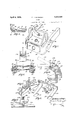
- Fig. 1 is a plan View of the clamp embodying the present invention.
- Fig. 2 is a side elevation of the clamp of Fig. l, but illustrating in addition the hold. down mechanism thereof.
- Fig. 3 is a sectional longitudinal elevation of the clamp of Fig. 1.
- Fig. 4 is a plan view of the integral frame of the clamp.
- Fig. 5 is a section along line 5-5 of Fig. 3.
- Fig. 6 is a perspective view of the movable aw.
- Fig. 7 is a perspective detail of the clamp frame and the fixed jaw.
- Fig. 8 is a sectional detail through one of the lugs of the fixed aw and supporting frame.
- Fig. 9 is a section taken along line 9--9 of Fig. 2.
- Fig. 10 is a sectional detail taken along line 10-10 of Fig. 9 and illustrating the two positions which the hold-down bar can assume in the supporting bracket.
- Fig. 11 is a perspective detail of the pressure foot.
- Fig. 12 is a longitudinal section taken through the pressure foot.
- the clamp embodying the present invention includes the integral frame that is illustrated in Fig. 4 and separately supports
- the frame is of U-shape and has the spaced and parallel legs or bars 14 which are free at the rear end of the clamp and are integrally connected together at the forward end of the clamp by a connecting member 16 which is integral with and is a continuation of the bars 14.
- the frame is formed of channel stock and has the upper and lower parallel flanges 18 and 20, respectively which are con tinuous in both the bars 14 and in the integral connecting member 16.
- the flanges in the bars are opposed.
- the free ends of the bars 14 are fixed to a supporting bracket 22 which has parallel outstanding lugs 24, see Fig. 9, that fit within the channels of the bars and so hold the bracket and bars together against relative angular movement therebetween. tightly against and are secured to the bracket by bolts 26 which pass through the bars and the lugs 24.
- This construction provides a frame which is exceptionally rigid especially at its forward end where the bars 14 are 3' .1
- the bracket is provided with a T-shaped slot 28 by which the clamp is connected with a supporting bar of a clamp carrier, the construction of which is not herein of importance and thus is not illustrated.
- the frame is provided with a fixed jaw 30 which upstands above and is extended transversely across the bars 14 at their integrally connected forward ends.
- the jaw has a forwardly extended foot 32 which rests upon the top flanges of said bar and also upon the top flange of the integral connecting member 16.
- the jaw and especially the foot 32 thereof is provided at its opposite ends with depending lugs 34 which overlie the flat sides 36 of the bars 14 and are secured thereto by suitable means as the rivets 38.
- the lugs 34 have inwardly curved projecting ends 40, see Fig. 8, which overlie the curved portion 42 only of the frame between the bars 14 and the integral member 16 but do not overlie the straight portion of said connecting member.
- the clamp is also provided with a movable jaw 44 which is located between the fixed jaw and the bracket 22 and upstands above and is extended transversely across the side bars 14 and has a foot 46 which rests upon 7 The ends of the bars are drawn the top flanges 18 of said side bars.
- the jaw is also provided with downwardly and forwardly extended arms 48 which overlie the outer flat vertical faces 36 of the bars 14 and have inwardly directed feet 50 which underlie and engage the bottom flanges 20 of the bars to hold the movable jaw perpendicular to the bars when it is clamped against the stock that is located between it and the fixed jaw.
- the movable aw is drawn toward the fixed jaw by means which includes a draw bar 52 which is located midway between the side bars 14 and has its flat face parallel with said bars. Said bar is 7 extended loosely through a slot 54 in a lug 56 which is integral i h the foot of the movable jaw and depends therebelow into the space between said bars 14 and forms a support which holds the rear free end of the bar in parallel relation with the bars 14 and also holds the be. from rotation.
- the narrow lower face of'the bar is serrated or is provided with a plurality of upwardly and rearwardly inclined notches 58 into any one of which a looking or connecting member carried by the loose jaw is adapted to be received whereby releasably to connect the jaw and draw bar together.
- the locking member includes a U-shaped frame 60 which is formed of a single piece of metal reflexed to provide downwardlyextended legs 62 and the upper integral connecting member 64. Said legs are extended slidably through vertical slots 66 formed in the foot 46 on opposite sides of the lug and have their free ends connected by a looking bar or bolt 68 which is riveted to the'euds of the legs 62 and is vertically movable in a slot 70 which is closed at the top and open at the bottom and which is extended trans verseiy through the lug 56 and opens into the bar-receiving slot 54.
- a compresslon spring 72 bears against the foot 46 and the connectmg member 64 of the looking frame and serves to maintain the frame yieldingly in elevated position with the bolt 68 in any selected slot 58 of the draw bar.
- the draw bar When the draw bar is moved forwardly, it mo ves the bolt 68 the abutment provided by the forward wall of the slot 70 and thereby transmits the clamping pressure directly to the movable aw without placing any stress upon the frame 60.
- Said forward wall of the slot 70 constitutes a draw member which depends from said movable jaw.
- the bolt can and is screw threaded into the hub 78 of a handle having the oppositely extended arms 80.
- the hub has an inner end portion 82 which fits rotatably within the circular hole 76 and provides a bearing for the hub and also has an enlarged annular outstanding flange 84 which bears against the outer face of the connecting member 16 of the frame and thereby exerts its pressure against said member and thus to the bars 14 when the handle is rotated to draw the movable jaw toward the fixed jaw.
- the handle is maintained in the aforesaid relation when it is reversely rotated by means of a semi-circular retaining member 86 which is received loosely in a peripheral groove 88 of the handle in front of the flange 84 and is seated in a groove provided in the under face of the foot 32 of the fixed jaw above the connecting member 16 and is secured removably to said foot by a screw 90.
- the rear end of the shaft 74 is provided with an upstanding flat end portion 92 which confronts the forward end of the draw bars 52.
- Connecting plates or straps 94 are disposed against the confronting ends of said shaft and bar and are connected thereto by the rivets 96 whereby to unite the two parts.
- Said plates 94 have oppositely extended lateral ends 98 which are located between the. flanges 18 and 20 of the frame bars 14 and thereby hold the shaft and draw bar against rotation whenthe screw threaded handle is rotated.
- the integral connecting member 16 of the frame directly supports the screw threaded shaft and handle and takes directly the stresses incident to the manipulation of the clamp. Since the member 16 is integral with the side bars 14, said bars are always rigidly connected as the connection is not dependent upon rivets which in time may work loose. The fixed aw is independent of the draw bar and handle and thus is not likely to become loose on the frame due to hammer blows on the handle but even if it should become loose, the clamp can be operated satisfactorily since the jaw is free to line itself for the work on the frame. If, by reason of grossly excessive pressure on the shaft, there is any tendency of the side bars to flex outwardly, they are held from such flexing by the depending arms 48 of the movable jaw. widely spaced so as to provide a firm support for the stock thereon. The flanges of the bars are relatively narrow so that there is little area on which glue can collect.
- the draw bar presents only its narrow top face to any glue that may drip from the stock so that there can be no great accumulation of glue thereon.
- the space between the side bars 14 and the draw bar 52 is freely open so that glue can drop through the frame without collecting thereon and bridging over the parts.
- the inwardly-directed feet 50 of the The integral bars 48 are relatively movable jaw are terminated close to the inner edges of the lower flanges 20 so that there is little chance for glue to collect on the feet.
- the lug 56 of the movable jaw through which the draw bar passes is disposed entirely under the foot 46 of the movable jaw and thus is protected from glue.
- the notches 58 in the draw bar are also preferably located in the bottom edge of the draw bar for the same reason.
- Said hold-down means includes a resilient bar 100 which has a connection with the supporting bracket 22 and overlies the clamping jaws and is provided with a pressure foot 102 that engages the work between the and to hold down the work against buckling.
- the pressure foot is loosely carried by a supporting member 104: that is slidable lengthwise of the bar and can be secured in any set position thereon by the thumb screw 108.
- the rear end of the bar has a rigid, as contrasted with a pivotal, connection it-h said supporting bracket 22 when the bar is in its operating position, and is adapted to be flexed downwardly to move the pressure foot into pressure engagement with the work.
- the forward end of the bar is held against itsinherent resiliency by means of a latch 108 that is pivotally connected by a screw 110 to the front face of the fixed jaw 30. lhe connection between the rear end of the hold-down bar and the bracket 22 is provided by an upstanding ear 112, see especially Fig.
- the recess 11% is provided with a horizontal bottom wall 116 at its forward end and notch 118 in its upper wall intermediate its ends and at the rear of said bottom wall into which the rear edge of the bar is adapted to be located when the bar is in use, the bottom face of the bar resting upon the bottom wall 116.
- the rear end of the bar is then supported against rocking movement so that the bar is caused to flex when the free end of the bar is pulled down to brin the pressure foot against the work.
- the rear end of the l is provided with an elongated notch 118 in its bottom face which (its loosely over a projection 120 that overlies the horizontal face 116 of the supporting bracket so that the bar can be located in its operative position from the forward end of the clamp.
- Suitable means as a bolt 122, is passed through the bar and through axially elongated slots 124 in the side walls of the socket so as to secure the bar against detachment from the socket while permitting it to be moved between the two positions above described.
- connection between the pressure foot 102 and the supporting member 104 is such that the foot can be forced or wedged against the work.
- a pin 126 carried by the supporting member is passed loosely through vertically elongated slots 128 in the opposite side walls of the pressure foot.
- a wedge 130 has a flat bottom face 132 which bears against the bottom wall of the pressure foot and has an inclined slot 134.111 which said pin 126 is located whereby to hold the wedge against detachment from the supporting member and foot.
- the bottom wall of the slot also constitutes a wedge face which is forced against the pin to urge the foot a ainst the stock.
- the bar 100 is hooked under the latch 108 and then the wedge driven rearwardly by a hammer, thus exerting pressure upwardly on the resilient bar, which is supported by the hook against upward movement, and downwardly on the pressure foot, thus forcing the latter against the w rk.
- This construction eliminates any adjustable connection between the bar and foot and permits a strong hold-down pressure to be applied to the stock.
- a clamp having a frame consisting of a channel member reflexed into a shape which provides parallel spaced bars that are free at the rear end of the frame and have a connecting member integral therewith at the forward end of the frame with the flanges of the channel being continuous in said bars and integral connecting member and confronting each other in said bars, a bracket rigidly connecting the free rear ends of said arms, a fixed clamping jaw secured to said bars at the forward end thereof, a movable jaw carried by said bars between said fixed jaw and bracket, and means to draw said movable jaw toward said fixed jaw including a draw bar connected with aid movable jaw and having ascrew threaded forward end which is passed loosely through said integral connecting member,
- an operating handle having a screw threaded connection with said screw threaded end and a bearing on said integral connecting member.
- a clamp having a frame consisting of spaced parallel bars of channel shape which have an integral connection at their forward ends, a bracket connecting the rear ends of said bars, a fixed jaw carried by said bars at the forward ends thereof, a movable jaw carried by said bars intermediate said fixed jaw and bracket, and a draw bar for moving said movable jaw toward said fixed jaw having a screw threaded shaft at its forward end which passes loosely through said connecting member and a handle screw threaded on said shaft and having a bearing directly on said connecting member for drawing said draw bar and movable jaw forwardly.
- a clamp having a frame consisting of spaced parallel bars of channel shape which have an integral connection at their forward ends, a bracket connecting the rear ends of said bars, a fixed aw carried by said bars at the forward ends thereof, a movable jaw carried by said bars intermediate said fixed jaw and bracket, and a draw bar for moving said movable jaw toward said fixed jaw having a screw threaded shaft at its forward end which passes loosely through said connecting member, a handle screw threaded on said shaft and having a bearing directly on said connecting member for drawing said draw bar and movable jaw forwardly, and means carried by said draw bar and engageable with said side bars for holding said draw bar against rotation.
- a clamp having spaced side bars, means connecting the forward ends: of said bars, a bracket connecting the rear ends of said bars, a jaw having means independent of said connecting means for securing said jaw fixedly to said bars, a movable jaw carried by said bars between said fixed jaw and bracket, and drawing means for said movable jaw having a bearing directly on said connecting means.
- a clamp having side bars, means connecting the forward ends of said side bars, a bracket connecting the rear ends of said bars, a jaw having means independent of said connecting means for securing it fixedly to said bars, a jaw movable on said bars between said fixed aw and bracket, a draw bar connected with said movable jaw and having a screw threaded shaft which is extended loosely through said connecting means, and an op erating handle having a screw threaded connection with said shaft and exerting pressure directly upon said connecting means for moving said movable aw toward said fixed aw.
- a clamp having spaced side bars, means rigidly connecting the forward ends of said bars, a bracket connecting the rear ends of said bars.
- a fixed jaw which is connected rigidly with said side bars and is free from connection with said connecting means, a jaw which is movable on said side bars toward said fixed jaw, and means which exerts a pressure directlv on said connecting means independently of said fixed jaw for moving said movable jaw toward said fixed jaw.
- a clamp having spaced side bars, a fixed jaw carried by said side bars, a aw movable on said side bars toward said fixed jaw, and means for drawing said movable jaw toward said fixed jaw which exerts a pressure directly on the forward ends of said side bars independently of said fixed jaw.
- a clamp having spaced side bars, means integrally connecting the forward ends of said side bars, a bracket connecting the rear ends of said bars, a jaw fixed to the forward ends of said bars, a jaw movable on said'bars between said fixed aw and bracket, rotatable jaw operating means socketed in said integral connecting means independently of said fixed jaw, and means operatively connecting said rotatable means and said movable jaw.
- a clamp having spaced side bars, means rigidly connecting the forward ends of said side bars, a bracket connecting the rear ends of said side bars, a jaw having means fixedly connecting it with said side bars independently of said bar connecting means, a jaw movable on said side bars, rotatable operating means for said movable jaw socketed in said bar-connecting means independently of said first mentioned jaw, and means operatively connecting said rotating means and said movable jaw.
- a clamp having a U-shaped framepro vided with parallel side bars and a connection 1 between said bars which is integral therewith at the forward ends thereof, a bracket connecting the rear ends of said bars, a jaw having means fixing it rigidly to said side bars in the rear of said integral connecting means, a jaw movable on said side bars between said fixed jaw and bracket, rotatable jaw operating means bearing directly on said integral connect-ing means, and a draw member connecting said rotatable means and movable aw.
- a clamp having spaced side bars, means connecting the forward ends of said bars, a bracket connecting the rear ends of said bars, a jaw having depending lugs which overlie the outer faces of said side bars, means rigidly securing said lugs to said side bars, a aw movable on said side bars between said fixed jaw and said bracket, rotatable jaw operating means bearing directly on said connecting means independently of said first mentioned jaw, and means including a draw bar connecting said rotatable means and said movable jaw.
- a clamp having spaced side bars of channel cross section arranged with their flanges in opposed confronting relation, means connecting the forward ends of said side bars, a bracket connecting the rear ends of said side bars, a jaw resting on said side bars and having dependent lugs which overlie the outer faces thereof, means securing said lugs fixedly to said side bars, a jaw movable on said side bars between said fixed jaw and said bracket, rotatable jaw operating means bearing directly upon said connecting means independently of said first mentioned jaw, and means including a draw bar operatively connecting said rotatable means and said movable jaw.
- a clamp having spaced side bars, a jaw fixed to the front ends of said side b rs, a jaw movable on said side bars having depending arms which overlie the outer faces of said side bars, and clamping means for drawing said movable jaw toward said fixed jaw including means to apply a clamping pressure on the forward ends of said bars independently of said first-mentioned jaw.
- A. clamp having spaced side bars, means connecting the forward ends of said side bars, a bracket connecting the rear ends of said side bars, a aw fixed directly to said side bars, a jaw movable on said side bars between said fixed aw and bracket and having depending arms that overlie the outer faces of said side bars, and means for drawing said movable jaw toward said fixed jaw including means which applies a clamping pressure directly on said connecting means independently of said fixed jaw.
- a clamp having spaced side bars which have inwardly directed confronting flanges, means connecting the forward ends of said side bars, a bracket connecting the rear ends of said side bars, a jaw resting upon said flanges and fixed rigidly to said side bars, a aw movable on said side bars between said fixed jaw and bracket having depending arms that overlie the outer faces of said side bars, and clamping means for drawing said movable jaw toward said fixed jaw including means which applies a clamping pressure directly on said connecting means independently of said fixed aw.
- a clamp having a frame consisting of parallel side bars and a connecting member integral with said bars at its forward end, a bracket connecting the rear ends of said bars, a jaw fixed to said frame at its forward end, a jaw movable on said frame between said fixed jaw and bracket having depending arms which overlie the outer faces of said side bars, and clamping means for drawing said movable jaw toward said fixed jaw including a rotatable clamping member which exerts a clamping pressure directly on said integral connecting means, and means including a draw bar for connecting said rot-atable means and said movable jaw.
- a clamp having a frame consisting of a channel member which has been reflexed to provide spaced side bars and a member integral therewith which connects said side bars at its forward end, the flanges of said channel member being in confronting relation in said side bars, a bracket connecting the rear ends of said side bars, a j aw resting upon said side bars having depending lugs which overlie the outer faces thereof, rivets passed through said lugs and side bars for fixedly connecting said jaw thereto, a jaw movable on said side bars between said fixed jaw and bracket having depending arms which overlie the outer faces of said side bars, a draw bar connected with said movable jaw and located between said side bars and extended through said integral connection, and an operating handle having a screw threaded connection with said draw bar and exerting a clamping pressure on said integral connecting member for drawing said movable jaw toward said fixed jaw.
- a clamp having spaced side bars provided with inwardly-directed confronting flanges, a jaw fixed to the forward ends of said side bars, a bracket secured to the rear ends of said side bars, a movable jaw located on said side bars between said fixed jaw and bracket, a draw bar for moving said movable jaw toward said fixed jaw having a screw threaded section, means including a rotatable member acting on said screw threaded section for moving said draw bar forwardly, and means connected with said draw bar and extended in opposite directions laterally thereof into confronting relation with the flanges of said side bars for holding said draw bar against rotation.
- a clamp having spaced side bars of channel cross section arranged with their flanges in inwardly directed confronting re lation, a jaw fixed to the forward end of the side bars, a jaw movable on said side bars, a draw bar connected with said movable jaw for moving it toward said fixed jaw having a screw threaded forward end, means including a rotatable member having a screw threaded connection with said screw threaded end for moving said bar forwardly, and means connected with said draw bar and extended laterally thereof into the space between the flanges of one of said side bars for engaging said flanges and holding said draw bar against rotation.
- a clamp having spaced side bars provided with inward]y-directed confronting flanges, a jaw fixed to the forward ends of said side bars, a jaw movable on said side bars toward said fixed jaw, a screw threaded shaft carried by said side bars, a handle screw threaded on said shaft for moving it axially, a draw bar connected with said movable jaw and axially aligned with and confronting said shaft, and means including straps that overlie and are connected with both said shaft and draw bar having oppositely directed ends which are disposed in confronting relation with the flanges of said side bars and hold said draw bar against rotation.
- a clamp having a U-shaped frame consisting of a channel bar which has been reflexed to provide spaced side bars and an integral connecting member at the for and ends of said bars, said bars having their flanges in inwardly directed confronting r lation,'a aw fixed to said side bars independent of said integral connecting member, a jaw movable 011 said side bars toward said fixed aw, a screw threaded shaft carried by said integral connecting-member, a handle screw threaded on said shaft for moving it axially, a draw bar connected with said movable jaw arranged in confronting and aligned relation with said screw threaded shaft, and straps disposed on opposite sides of said shaft and draw bar and connected with both and having their ends oppositely extended 1 into confronting relation with the flanges of said side bars whereby to hold said draw bar against rotation.
- a glue clamp having spaced side bars having upper and lower inwardly directed flanges, a jaw fixed to said side bars, a. jaw movable on said side bars having downwardly depending arms which overlie the outer faces of said side bars and have inwardlydirected separate feet which underlie and engage the bottom faces of the lower flanges of said side bars and are terminated at said bottom faces, and means for drawing said movable aw toward said fixed jaw.
- a supporting frame having spaced side bars, a jaw fixed to said side bars, a jaw movable on said side bars, a draw bar for moving said movable jaw toward said fixed aw located loosely in a slot in said movable jaw, said draw bar having a series of recesses therein, a locking member extended across said slot and engageable with said movable jaw on opposite sides thereof and adapted to be received in a selected one of said recesses for connecting said draw bar and jaw together, and means for moving said locking member into and out of engagement with said recesses.
- a clamp In a clamp, a supporting frame, a jaw fixed to said frame, a jaw movable on said frame having a draw-member depending below the top of said frame, a draw bar arranged for connection with said draw memher for moving said movable jaw along said frame, and connecting means carried by said movable jaw'including a member extending transversely of and movable into engagement with said draw member and into and out of engagement with said draw bar.
- a fine.” jaw In a clamp, 21- supporting frame, a fine.” jaw, a movable jaw having slotte member provided ith a recess which is transverse of and opens into said slot, said recess closed at the top and open at the bottom, a draw-bar located in said slot for moving said movable jaw along said frame, and a connecting me ber carried by said movable jaw and mov no in said recess through the open bottom th of into and out of operative engagement v said draw bar.
- a clamp In a clamp, a supporting frame, a fixed jaw, a movable jaw, a draw-bar for moving said movable jaw along said frame, and lockingmeans for connecting said draw bar and movable jaw including a locking member extended transversely of said draw-bar and movable into and out of engagement therewith, an operating structure for said locking member slidably carried by said movable jaw and connected to the ends of said transversely extending locking member, and means for holding said operatin structure releasably in the connected condition of said draw bar.
- a clamp a supporting frame, a fixed jaw, a movable jaw, a draw bar for moving said movable jaw along said frame, and locking means for connecting said draw bar and movable jaw including a lockin member extended transversely of said draw bar and movable into and out of engagement therewith, said movable jaw having an abutment over which said locking member is movable and against which it is urged by said draw bar, and supporting means for said locking member having a slidable connection with said movable aw.
- a draw-bar a supporting frame, a fixed jaw, a movable jaw, a serrated drawbar received in a. recess in said movable jaw, for moving said movable jaw toward said. fixed jaw, and locking means for releasably connecting said draw bar with said movable jaw including a frame having spaced arms which have a sliding engagement with said movable jaw and which are located on opposite sides of said draw-bar, a bolt connected with said arms and extended transversely of said draw bar in position to enter a selected serration thereof, and spring bearing on said frame in a direction to hold said frame connected with said draw bar.
- a clamp a supporting frame, a fixed jaw, a movable jaw, a draw-bar for moving said movable jaw along said frame, means releasably connecting said draw-bar and movable jaw including a bolt extending transversely of said draw-bar beyond both sides thereof, a supporting structure connected to the ends of said bolt and movable to move said bolt into and out of engagement with said oraw-bar, and means for connecting said draw-bar directly with said movable aw through said bolt and excluding said supporting structure from said connection.
- a supporting frame relatively movable jaws carried by said frame, and hold-down mechanism for the work between said jaws including a resilient bar disposed above said jaws, a work-engaging foot on said bar, and a fixed supporting member for an end of said bar having means for bolding said bar against rocking in two angular: 1y related positions which admits movement of said her in said supporting member from one position to the other.
- a clamp a supporting frame, relatively movable jaws carried by said frame, and hold-down mechanism for the work between said jaws including a bar disposed above said awe, a work-engaging foot on said bar, and a fixed supporting member for an end of said bar which has means providing two angularly-related rigid supports for the end of said bar, said bar being resilient and adapted to be flexed from its fixed end toward the work.
- a supporting frame relatively movable jaws carried by said frame, hold-down mechanism for the work between said aws including a bar disposed above said jaws, a work-engaging foot on said bar, a fixed supporting memb r for an end of said bar which has means providing two angularlyrelated rigid supports for the end of said bar, said bar being resilient and adapted to be flexed from its fixed end toward the work, and means connecting said end of said bar against its detachment from said supporting member which admits of movement of said bar between said supports.
- a supporting frame relatively movable jaws carried by said frame, and hold-down mechanism for the work between said jaws including a bar disposed above said jaws, a work-engaging foot on said bar, a fixed supporting member for an end of said bar having a socket in which an end of said bar is located, said socket having angularly-related bar-engaging surfaces which support said bar rigidly in two angularlyrelated positions, said bar being resilient and adapted to be flexed from its ri idly sup ported end toward the work.
- a clamp In a clamp, a supporting frame, relatively movable jaws carried by said frame,
- hold-down mechanism for the work between said jaws including a bar disposed above said jaws, work-engaging foot on said bar, a fixed supporting member for an end of said bar having a socket in which an end of said bar is located, said socket having angularly-related bar engaging surfaces which support said bar rigidly in two angularlyrelated positions, said bar being resilient and adapted to be flexed from its rigidly supported end toward the work, and means loosely securing said bar in said socket against detachment therefrom which admits movement of said bar between said two positions.
- a supporting frame relatively movable jaws carried by said frame, hold-down mechanism for he work between said jaws including a bar disposed above said jaws, a work-engaging foot on said bar, a fixed supporting member for an end of said bar having an open-ended socket which is inclined upwardly away from said supporting frame and which has a bar-supporting face that is parallel with said frame and a notch opposed to and in the rear of said face, said bar being receivable in said socket and held thereby in an inclined position with respect to said supporting frame and also being movable in said socket into a position where it rests upon said face and has its end located in said notch, said bar also being resilient and adapted to be flexed toward the work.
- a supporting frame relatively movable jaws carried by said frame, hold-down mechanism for the work between said jaws including a bar disposed above said jaws, a work-engaging foot on said bar, a fixed supporting member for an end of said bar having an open-ended socket which is inclined upwardly away from said supporting frame and has a bar-supporting face that is parallel with said frame and a notch opposed to and in the rear of said face, said bar being receivable in said socket and held thereby in an inclined position with respect to said supporting frame and also being movable in said socket into a position where it rests upon said face and has its end located in said notch, said bar also being resilient and adapted to be flexed toward the work, and means connecting said bar loosely against detachment from said socket which admits of the above-described movement of said bar therein.
- a clamp having the combination of a work-supporting frame, aws on said frame between which the work is clamped, and hold-down mechanism for the clamped work including a bar extended above the work having means to support it against upward displacement, a pressure foot engageable with the work, a supporting member movable lengthwise of and carried by said bar having a loose connection with said foot, and a wedge which is interposed between and is movable relatively both to said supporting member and to said foot and which forces said foot away from said bar and against the work.
- a clamp having the combination of a work-supporting frame, jaws on said frame between which the work is clamped, and hold-down mechanism for the clamped work including a bar extended above the work having means to support it against upward displacement, a pressure foot engageable with the work, a supporting member movable lengthwise of and carried by said bar having a loose connection with said foot, and a wedge which is interposed between and is movable relatively both to said supporting member and to said foot and having a loose connection with said supporting member arranged to force said pressure foot against the work.
- a clamp having the combination of a work-supporting frame, jaws on said frame between which the work is clamped, and hold-down mechanism for the clamped work including a bar extended above the work having means to support it against upward displacement, a pressure foot engageable with the work, a supporting member movable lengthwise of and carried by said bar, a pin carried by said supporting member received in a vertically-elongated slot in said pressure foot, and a wedge located between said pressure foot and supporting member for urging said pressure foot against the work having a wedge slot in which said pin is loosely received.
- a clamp having the combination of a work-supporting frame, jaws on said frame between which the work is clamped, and hold-down mechanism for the clamped work including a bar extended above the work having means to support it against upward displacement, a pressure foot engageable with the work, a supporting member movable lengthwise of and carried by said bar having a loose connection with said foot, and wedging means which forces said foot away from said bar and against the work having a loose connection with said supporting member.
Landscapes
- Engineering & Computer Science (AREA)
- Mechanical Engineering (AREA)
- Clamps And Clips (AREA)
Description
April 5, 1932. E. .1. MCKNIGH'T CLAMP Filed Jan. 15, 1950 2 Sheets-Sheet 1570877702". vfi v A. 4130 1;
April 1932- E J. MCKNIGHT 1,852,586
CLAMP Filed Jan. 151930 2 Sheets-Sheet 2 I ium EMA m1- W Patented Apr. 5, 1932 UNITED STATES ELLIOTT J. MCKNIG-HT, OF GARDNER, MASSACHUSETTS CLAMP Application filed January 15, 1930. Serial No. 420,911.
they are loaded with the glued stock and are then moved beyond such position and hold the glued stock until the glue has set and while successive other clamps are being loaded. The clamp, however, is not necessarily restricted to such use.
In use, the parts of the clamp become covered with glue which can interfere with the satisfactory and speedy operation of the clamp unless these conditions are recognized u and guarded against by a proper design of the clamp; and such a clamp constitutes one of the objects of the present invention.
A further object of the invention is the provision of a clamp having worksupporting bars that are relatively widely spaced so that a support is provided for the work on which the work is stable and wherein the bars have relatively narrow work-engaging surfaces, so as to present little area on which glue can collect.
The clamp is provided with a movable jaw that can be drawn toward the otherjaw, which is fixed to the supporting bars by means which includes a screw-threaded shaft and a handle that is screw-threaded on the shaft. In commercial use, these clamps are roughly handled. When the clamp is operated, the handle usually is spun upon the shaft to bring the jaws rapidly into initial engagement with the stock and then the handle is struck with a hammer to set the jaws tightly against the stock. In some clamps of this nature, the fixed jaw is riveted or bolted to the supporting bars and constitutes the only means connecting the bars and also carries the screw threaded shaft or the handle. Due to the action of the hammer blows and the vibration caused thereby, the fixed jaw can work loose on the supporting bar. Since seve jointly along the length of stock which is extended between all of them, a loose jaw can be out of line with the other fixed jaws and thus can not do its work effectively. Consequently, a further object of the present invention is the provision of a clamp wherein the draw shaft and its operating handle or nut are carried by the supporting bars entirely independent of the fixed jaw so that the jaw is free from the direct impacts applied to s the handle and shaft in service and thus is not subjected to sudden forces which tend to distort the jaw and to loosen its connection with and its alignment on the bars.
As has been stated, the bars of some clamps are connected together at their forward ends by means of the fixed jaw and, if the rivets of the connecting means become loose, the bars are no longer rigidly connected at their forward ends and thus are free to weave so that the clamp loses its rigidity and can not do accurate and rapid work. Thus, a further and essential object of the invention is the provision of a clamp wherein the supporting bars are integrally connected at the forward 7. end of the clamp so that the bars are rigid at all times, the bars being made from a single length of structural steel which is reflexed into substantially U-shape and provides a support for the fixed jaw at the integral connection between the legs. The integral construction is rigid at all times and is exceedingly well adapted to receive the severe use to which these clamps are put.
A; further object is the provision of a supporting frame which consists of an integral and unitary construction, as contrasted with a frame composed of separate parts riveted together, and which provides a support independently for the fixed and movable jaws and the draw-mechanism for moving the movable jaw toward the fixed jaw.
The movable jaw rides upon the side bars of the clamp and is drawn toward the fixed bar by a draw bar fixed to the above-mentioned screw-threaded shaft. It is an object of the present invention to prevent rotation of the shaft and the draw bar by having the sidebars of the clamp of channel shape with the flanges of the channels in opposed confronting relation and to have lateral extensions of the shaft and draw bar received loosely between and in confronting relation with the flanges which flanges act to hold said extension and thereby the shaft and draw bar from rotating.
The movable jaw can be connected with the draw bar in any one of a plurality of positions along the length thereof by means of a locking or connecting member carried by the jaw which engages any one of a series of recesses formed and arranged in line along the length of the draw bar. An object of the present invention is to so arrange the recesses and the locking member that the locking member acts as a bolt to connect the draw bar and jaw directly so that there is little tendency for the locking member to bend or be otherwise distorted, and, furthermore, to so arrange the recesses and locking member that the locking member is caused to be fully seated in any selected recess as soon as pressure is applied to the jaw.
When wide stock is clamped between the jaws and has a tendency to buckle upwardly therebetween, a hold-down mechanism is provided which includes a pressure foot that is located above the stock and is carried by a resilient bar that can be flexed downward toward the stock to hold the pressure foot in pressure engagement with the work. The hold-down bar is usually carried by a member located at the rear end of the clamp, as the supporting bracket. An object of the present invention is to provide improved means for operatively connecting the hold-down bar and the supporting bracket so that the holddown bar can be supported in an operative position for flexure into holding engagement with the work and also in an elevated and out-of-use position when the character of the work is such that the hold-down bar is not necessary.
A further object of the invention is generally to improve the construction and operation of glue clamps.
Fig. 1 is a plan View of the clamp embodying the present invention.
Fig. 2 is a side elevation of the clamp of Fig. l, but illustrating in addition the hold. down mechanism thereof.
Fig. 3 is a sectional longitudinal elevation of the clamp of Fig. 1.
' Fig. 4 is a plan view of the integral frame of the clamp.
Fig. 5 is a section along line 5-5 of Fig. 3. Fig. 6 is a perspective view of the movable aw.
Fig. 7 is a perspective detail of the clamp frame and the fixed jaw.
Fig. 8 is a sectional detail through one of the lugs of the fixed aw and supporting frame.
Fig. 9 is a section taken along line 9--9 of Fig. 2.
the component parts of the clamp.
Fig. 10 is a sectional detail taken along line 10-10 of Fig. 9 and illustrating the two positions which the hold-down bar can assume in the supporting bracket.
Fig. 11 is a perspective detail of the pressure foot.
Fig. 12 is a longitudinal section taken through the pressure foot.
The clamp embodying the present invention includes the integral frame that is illustrated in Fig. 4 and separately supports The frame is of U-shape and has the spaced and parallel legs or bars 14 which are free at the rear end of the clamp and are integrally connected together at the forward end of the clamp by a connecting member 16 which is integral with and is a continuation of the bars 14. The frame is formed of channel stock and has the upper and lower parallel flanges 18 and 20, respectively which are con tinuous in both the bars 14 and in the integral connecting member 16. The flanges in the bars are opposed. The free ends of the bars 14 are fixed to a supporting bracket 22 which has parallel outstanding lugs 24, see Fig. 9, that fit within the channels of the bars and so hold the bracket and bars together against relative angular movement therebetween. tightly against and are secured to the bracket by bolts 26 which pass through the bars and the lugs 24. This construction provides a frame which is exceptionally rigid especially at its forward end where the bars 14 are 3' .1
integrally connected and where the stresses on the clamp are the greatest.
The bracket is provided with a T-shaped slot 28 by which the clamp is connected with a supporting bar of a clamp carrier, the construction of which is not herein of importance and thus is not illustrated. The frame is provided with a fixed jaw 30 which upstands above and is extended transversely across the bars 14 at their integrally connected forward ends. The jaw has a forwardly extended foot 32 which rests upon the top flanges of said bar and also upon the top flange of the integral connecting member 16. The jaw and especially the foot 32 thereof is provided at its opposite ends with depending lugs 34 which overlie the flat sides 36 of the bars 14 and are secured thereto by suitable means as the rivets 38. The lugs 34 have inwardly curved projecting ends 40, see Fig. 8, which overlie the curved portion 42 only of the frame between the bars 14 and the integral member 16 but do not overlie the straight portion of said connecting member.
The clamp is also provided with a movable jaw 44 which is located between the fixed jaw and the bracket 22 and upstands above and is extended transversely across the side bars 14 and has a foot 46 which rests upon 7 The ends of the bars are drawn the top flanges 18 of said side bars. The jaw is also provided with downwardly and forwardly extended arms 48 which overlie the outer flat vertical faces 36 of the bars 14 and have inwardly directed feet 50 which underlie and engage the bottom flanges 20 of the bars to hold the movable jaw perpendicular to the bars when it is clamped against the stock that is located between it and the fixed jaw.
The movable aw is drawn toward the fixed jaw by means which includes a draw bar 52 which is located midway between the side bars 14 and has its flat face parallel with said bars. Said bar is 7 extended loosely through a slot 54 in a lug 56 which is integral i h the foot of the movable jaw and depends therebelow into the space between said bars 14 and forms a support which holds the rear free end of the bar in parallel relation with the bars 14 and also holds the be. from rotation. The narrow lower face of'the bar is serrated or is provided with a plurality of upwardly and rearwardly inclined notches 58 into any one of which a looking or connecting member carried by the loose jaw is adapted to be received whereby releasably to connect the jaw and draw bar together. The locking member includes a U-shaped frame 60 which is formed of a single piece of metal reflexed to provide downwardlyextended legs 62 and the upper integral connecting member 64. Said legs are extended slidably through vertical slots 66 formed in the foot 46 on opposite sides of the lug and have their free ends connected by a looking bar or bolt 68 which is riveted to the'euds of the legs 62 and is vertically movable in a slot 70 which is closed at the top and open at the bottom and which is extended trans verseiy through the lug 56 and opens into the bar-receiving slot 54. A compresslon spring 72 bears against the foot 46 and the connectmg member 64 of the looking frame and serves to maintain the frame yieldingly in elevated position with the bolt 68 in any selected slot 58 of the draw bar. When the draw bar is moved forwardly, it mo ves the bolt 68 the abutment provided by the forward wall of the slot 70 and thereby transmits the clamping pressure directly to the movable aw without placing any stress upon the frame 60. Said forward wall of the slot 70 constitutes a draw member which depends from said movable jaw. The bolt can and is screw threaded into the hub 78 of a handle having the oppositely extended arms 80. The hub has an inner end portion 82 which fits rotatably within the circular hole 76 and provides a bearing for the hub and also has an enlarged annular outstanding flange 84 which bears against the outer face of the connecting member 16 of the frame and thereby exerts its pressure against said member and thus to the bars 14 when the handle is rotated to draw the movable jaw toward the fixed jaw. The handle is maintained in the aforesaid relation when it is reversely rotated by means of a semi-circular retaining member 86 which is received loosely in a peripheral groove 88 of the handle in front of the flange 84 and is seated in a groove provided in the under face of the foot 32 of the fixed jaw above the connecting member 16 and is secured removably to said foot by a screw 90. The rear end of the shaft 74 is provided with an upstanding flat end portion 92 which confronts the forward end of the draw bars 52. Connecting plates or straps 94 are disposed against the confronting ends of said shaft and bar and are connected thereto by the rivets 96 whereby to unite the two parts. Said plates 94 have oppositely extended lateral ends 98 which are located between the. flanges 18 and 20 of the frame bars 14 and thereby hold the shaft and draw bar against rotation whenthe screw threaded handle is rotated.
As thus arranged, the integral connecting member 16 of the frame directly supports the screw threaded shaft and handle and takes directly the stresses incident to the manipulation of the clamp. Since the member 16 is integral with the side bars 14, said bars are always rigidly connected as the connection is not dependent upon rivets which in time may work loose. The fixed aw is independent of the draw bar and handle and thus is not likely to become loose on the frame due to hammer blows on the handle but even if it should become loose, the clamp can be operated satisfactorily since the jaw is free to line itself for the work on the frame. If, by reason of grossly excessive pressure on the shaft, there is any tendency of the side bars to flex outwardly, they are held from such flexing by the depending arms 48 of the movable jaw. widely spaced so as to provide a firm support for the stock thereon. The flanges of the bars are relatively narrow so that there is little area on which glue can collect.
The draw bar presents only its narrow top face to any glue that may drip from the stock so that there can be no great accumulation of glue thereon. The space between the side bars 14 and the draw bar 52 is freely open so that glue can drop through the frame without collecting thereon and bridging over the parts.
The inwardly-directed feet 50 of the The integral bars 48 are relatively movable jaw are terminated close to the inner edges of the lower flanges 20 so that there is little chance for glue to collect on the feet. The lug 56 of the movable jaw through which the draw bar passes is disposed entirely under the foot 46 of the movable jaw and thus is protected from glue. The notches 58 in the draw bar are also preferably located in the bottom edge of the draw bar for the same reason.
lVhen stock is put together to form wide boards between the jaws there is sometimes a tendency for the stock to buckle upwardly away from the top surface of the bars 14. Means are provided, which can be used when needed, to hold the stock down onto the bars and thus to prevent such buckling. Said hold-down means includes a resilient bar 100 which has a connection with the supporting bracket 22 and overlies the clamping jaws and is provided with a pressure foot 102 that engages the work between the and to hold down the work against buckling. The pressure foot is loosely carried by a supporting member 104: that is slidable lengthwise of the bar and can be secured in any set position thereon by the thumb screw 108. The rear end of the bar has a rigid, as contrasted with a pivotal, connection it-h said supporting bracket 22 when the bar is in its operating position, and is adapted to be flexed downwardly to move the pressure foot into pressure engagement with the work. The forward end of the bar is held against itsinherent resiliency by means of a latch 108 that is pivotally connected by a screw 110 to the front face of the fixed jaw 30. lhe connection between the rear end of the hold-down bar and the bracket 22 is provided by an upstanding ear 112, see especially Fig. 10, which has an elongated r cess 114 therein that is of square cross section to conform with the cross section of the hold-down bar and is forwardly and upwardly directed so that when the hold-down bar is in the dotted and out-of-use position illustrated in Fig. 10 and is in the bottom of the recess, the bar and the pressure foot thereon are held above the clamping jaws so that stock can be inserted therein without interference from said bar. The recess 11% is provided with a horizontal bottom wall 116 at its forward end and notch 118 in its upper wall intermediate its ends and at the rear of said bottom wall into which the rear edge of the bar is adapted to be located when the bar is in use, the bottom face of the bar resting upon the bottom wall 116. The rear end of the bar is then supported against rocking movement so that the bar is caused to flex when the free end of the bar is pulled down to brin the pressure foot against the work. The rear end of the l is provided with an elongated notch 118 in its bottom face which (its loosely over a projection 120 that overlies the horizontal face 116 of the supporting bracket so that the bar can be located in its operative position from the forward end of the clamp. When the bar is to be moved into its out-of-use position, it is merely raised upwardly and pushed rearwardly into the bottom of the socket 114. Suitable means, as a bolt 122, is passed through the bar and through axially elongated slots 124 in the side walls of the socket so as to secure the bar against detachment from the socket while permitting it to be moved between the two positions above described.
' The connection between the pressure foot 102 and the supporting member 104 is such that the foot can be forced or wedged against the work. To this end, a pin 126 carried by the supporting member is passed loosely through vertically elongated slots 128 in the opposite side walls of the pressure foot. A wedge 130 has a flat bottom face 132 which bears against the bottom wall of the pressure foot and has an inclined slot 134.111 which said pin 126 is located whereby to hold the wedge against detachment from the supporting member and foot. The bottom wall of the slot also constitutes a wedge face which is forced against the pin to urge the foot a ainst the stock. in use, the bar 100 is hooked under the latch 108 and then the wedge driven rearwardly by a hammer, thus exerting pressure upwardly on the resilient bar, which is supported by the hook against upward movement, and downwardly on the pressure foot, thus forcing the latter against the w rk. This construction eliminates any adjustable connection between the bar and foot and permits a strong hold-down pressure to be applied to the stock.
I claim:
1. A clamp having a frame consisting of a channel member reflexed into a shape which provides parallel spaced bars that are free at the rear end of the frame and have a connecting member integral therewith at the forward end of the frame with the flanges of the channel being continuous in said bars and integral connecting member and confronting each other in said bars, a bracket rigidly connecting the free rear ends of said arms, a fixed clamping jaw secured to said bars at the forward end thereof, a movable jaw carried by said bars between said fixed jaw and bracket, and means to draw said movable jaw toward said fixed jaw including a draw bar connected with aid movable jaw and having ascrew threaded forward end which is passed loosely through said integral connecting member,
,and an operating handle having a screw threaded connection with said screw threaded end and a bearing on said integral connecting member.
2. A clamp having a frame consisting of spaced parallel bars of channel shape which have an integral connection at their forward ends, a bracket connecting the rear ends of said bars,a fixed jaw carried by said bars at the forward ends thereof, a movable jaw carried by said bars intermediate said fixed jaw and bracket, and a draw bar for moving said movable jaw toward said fixed jaw having a screw threaded shaft at its forward end which passes loosely through said connecting member and a handle screw threaded on said shaft and having a bearing directly on said connecting member for drawing said draw bar and movable jaw forwardly.
3. A clamp having a frame consisting of spaced parallel bars of channel shape which have an integral connection at their forward ends, a bracket connecting the rear ends of said bars, a fixed aw carried by said bars at the forward ends thereof, a movable jaw carried by said bars intermediate said fixed jaw and bracket, and a draw bar for moving said movable jaw toward said fixed jaw having a screw threaded shaft at its forward end which passes loosely through said connecting member, a handle screw threaded on said shaft and having a bearing directly on said connecting member for drawing said draw bar and movable jaw forwardly, and means carried by said draw bar and engageable with said side bars for holding said draw bar against rotation.
4:. A clamp having spaced side bars, means connecting the forward ends: of said bars, a bracket connecting the rear ends of said bars, a jaw having means independent of said connecting means for securing said jaw fixedly to said bars, a movable jaw carried by said bars between said fixed jaw and bracket, and drawing means for said movable jaw having a bearing directly on said connecting means.
5. A clamp having side bars, means connecting the forward ends of said side bars, a bracket connecting the rear ends of said bars, a jaw having means independent of said connecting means for securing it fixedly to said bars, a jaw movable on said bars between said fixed aw and bracket, a draw bar connected with said movable jaw and having a screw threaded shaft which is extended loosely through said connecting means, and an op erating handle having a screw threaded connection with said shaft and exerting pressure directly upon said connecting means for moving said movable aw toward said fixed aw.
6. A clamp having spaced side bars, means rigidly connecting the forward ends of said bars, a bracket connecting the rear ends of said bars. a fixed jaw which is connected rigidly with said side bars and is free from connection with said connecting means, a jaw which is movable on said side bars toward said fixed jaw, and means which exerts a pressure directlv on said connecting means independently of said fixed jaw for moving said movable jaw toward said fixed jaw.
7. A clamp having spaced side bars, a fixed jaw carried by said side bars, a aw movable on said side bars toward said fixed jaw, and means for drawing said movable jaw toward said fixed jaw which exerts a pressure directly on the forward ends of said side bars independently of said fixed jaw.
8. A clamp having spaced side bars, means integrally connecting the forward ends of said side bars, a bracket connecting the rear ends of said bars, a jaw fixed to the forward ends of said bars, a jaw movable on said'bars between said fixed aw and bracket, rotatable jaw operating means socketed in said integral connecting means independently of said fixed jaw, and means operatively connecting said rotatable means and said movable jaw.
9. A clamp having spaced side bars, means rigidly connecting the forward ends of said side bars, a bracket connecting the rear ends of said side bars, a jaw having means fixedly connecting it with said side bars independently of said bar connecting means, a jaw movable on said side bars, rotatable operating means for said movable jaw socketed in said bar-connecting means independently of said first mentioned jaw, and means operatively connecting said rotating means and said movable jaw.
10. A clamp having a U-shaped framepro vided with parallel side bars and a connection 1 between said bars which is integral therewith at the forward ends thereof, a bracket connecting the rear ends of said bars, a jaw having means fixing it rigidly to said side bars in the rear of said integral connecting means, a jaw movable on said side bars between said fixed jaw and bracket, rotatable jaw operating means bearing directly on said integral connect-ing means, and a draw member connecting said rotatable means and movable aw.
11. A clamp having spaced side bars, means connecting the forward ends of said bars, a bracket connecting the rear ends of said bars, a jaw having depending lugs which overlie the outer faces of said side bars, means rigidly securing said lugs to said side bars, a aw movable on said side bars between said fixed jaw and said bracket, rotatable jaw operating means bearing directly on said connecting means independently of said first mentioned jaw, and means including a draw bar connecting said rotatable means and said movable jaw.
12. A clamp having spaced side bars of channel cross section arranged with their flanges in opposed confronting relation, means connecting the forward ends of said side bars, a bracket connecting the rear ends of said side bars, a jaw resting on said side bars and having dependent lugs which overlie the outer faces thereof, means securing said lugs fixedly to said side bars, a jaw movable on said side bars between said fixed jaw and said bracket, rotatable jaw operating means bearing directly upon said connecting means independently of said first mentioned jaw, and means including a draw bar operatively connecting said rotatable means and said movable jaw.
13. A clamp having spaced side bars, a jaw fixed to the front ends of said side b rs, a jaw movable on said side bars having depending arms which overlie the outer faces of said side bars, and clamping means for drawing said movable jaw toward said fixed jaw including means to apply a clamping pressure on the forward ends of said bars independently of said first-mentioned jaw.
14. A. clamp having spaced side bars, means connecting the forward ends of said side bars, a bracket connecting the rear ends of said side bars, a aw fixed directly to said side bars, a jaw movable on said side bars between said fixed aw and bracket and having depending arms that overlie the outer faces of said side bars, and means for drawing said movable jaw toward said fixed jaw including means which applies a clamping pressure directly on said connecting means independently of said fixed jaw.
15. A clamp having spaced side bars which have inwardly directed confronting flanges, means connecting the forward ends of said side bars, a bracket connecting the rear ends of said side bars, a jaw resting upon said flanges and fixed rigidly to said side bars, a aw movable on said side bars between said fixed jaw and bracket having depending arms that overlie the outer faces of said side bars, and clamping means for drawing said movable jaw toward said fixed jaw including means which applies a clamping pressure directly on said connecting means independently of said fixed aw.
16. A clamp having a frame consisting of parallel side bars and a connecting member integral with said bars at its forward end, a bracket connecting the rear ends of said bars, a jaw fixed to said frame at its forward end, a jaw movable on said frame between said fixed jaw and bracket having depending arms which overlie the outer faces of said side bars, and clamping means for drawing said movable jaw toward said fixed jaw including a rotatable clamping member which exerts a clamping pressure directly on said integral connecting means, and means including a draw bar for connecting said rot-atable means and said movable jaw.
17. A clamp having a frame consisting of a channel member which has been reflexed to provide spaced side bars and a member integral therewith which connects said side bars at its forward end, the flanges of said channel member being in confronting relation in said side bars, a bracket connecting the rear ends of said side bars, a j aw resting upon said side bars having depending lugs which overlie the outer faces thereof, rivets passed through said lugs and side bars for fixedly connecting said jaw thereto, a jaw movable on said side bars between said fixed jaw and bracket having depending arms which overlie the outer faces of said side bars, a draw bar connected with said movable jaw and located between said side bars and extended through said integral connection, and an operating handle having a screw threaded connection with said draw bar and exerting a clamping pressure on said integral connecting member for drawing said movable jaw toward said fixed jaw.
18. A clamp having spaced side bars provided with inwardly-directed confronting flanges, a jaw fixed to the forward ends of said side bars, a bracket secured to the rear ends of said side bars, a movable jaw located on said side bars between said fixed jaw and bracket, a draw bar for moving said movable jaw toward said fixed jaw having a screw threaded section, means including a rotatable member acting on said screw threaded section for moving said draw bar forwardly, and means connected with said draw bar and extended in opposite directions laterally thereof into confronting relation with the flanges of said side bars for holding said draw bar against rotation.
19. A clamp having spaced side bars of channel cross section arranged with their flanges in inwardly directed confronting re lation, a jaw fixed to the forward end of the side bars, a jaw movable on said side bars, a draw bar connected with said movable jaw for moving it toward said fixed jaw having a screw threaded forward end, means including a rotatable member having a screw threaded connection with said screw threaded end for moving said bar forwardly, and means connected with said draw bar and extended laterally thereof into the space between the flanges of one of said side bars for engaging said flanges and holding said draw bar against rotation.
20. A clamp having spaced side bars provided with inward]y-directed confronting flanges, a jaw fixed to the forward ends of said side bars, a jaw movable on said side bars toward said fixed jaw, a screw threaded shaft carried by said side bars, a handle screw threaded on said shaft for moving it axially, a draw bar connected with said movable jaw and axially aligned with and confronting said shaft, and means including straps that overlie and are connected with both said shaft and draw bar having oppositely directed ends which are disposed in confronting relation with the flanges of said side bars and hold said draw bar against rotation.
21. A clamp having a U-shaped frame consisting of a channel bar which has been reflexed to provide spaced side bars and an integral connecting member at the for and ends of said bars, said bars having their flanges in inwardly directed confronting r lation,'a aw fixed to said side bars independent of said integral connecting member, a jaw movable 011 said side bars toward said fixed aw, a screw threaded shaft carried by said integral connecting-member, a handle screw threaded on said shaft for moving it axially, a draw bar connected with said movable jaw arranged in confronting and aligned relation with said screw threaded shaft, and straps disposed on opposite sides of said shaft and draw bar and connected with both and having their ends oppositely extended 1 into confronting relation with the flanges of said side bars whereby to hold said draw bar against rotation.
22. A glue clamp having spaced side bars having upper and lower inwardly directed flanges, a jaw fixed to said side bars, a. jaw movable on said side bars having downwardly depending arms which overlie the outer faces of said side bars and have inwardlydirected separate feet which underlie and engage the bottom faces of the lower flanges of said side bars and are terminated at said bottom faces, and means for drawing said movable aw toward said fixed jaw.
23. In a clamp, a supporting frame having spaced side bars, a jaw fixed to said side bars, a jaw movable on said side bars, a draw bar for moving said movable jaw toward said fixed aw located loosely in a slot in said movable jaw, said draw bar having a series of recesses therein, a locking member extended across said slot and engageable with said movable jaw on opposite sides thereof and adapted to be received in a selected one of said recesses for connecting said draw bar and jaw together, and means for moving said locking member into and out of engagement with said recesses.
12%. In a clamp, a supporting frame, a jaw fixed to said frame, a jaw movable on said frame having a draw-member depending below the top of said frame, a draw bar arranged for connection with said draw memher for moving said movable jaw along said frame, and connecting means carried by said movable jaw'including a member extending transversely of and movable into engagement with said draw member and into and out of engagement with said draw bar.
25. In a clamp, 21- supporting frame, a fine." jaw, a movable jaw having slotte member provided ith a recess which is transverse of and opens into said slot, said recess closed at the top and open at the bottom, a draw-bar located in said slot for moving said movable jaw along said frame, and a connecting me ber carried by said movable jaw and mov no in said recess through the open bottom th of into and out of operative engagement v said draw bar.
26. In a clamp, a supporting frame, a fixed jaw, a movable jaw, a draw-bar for moving said movable jaw along said frame, and lockingmeans for connecting said draw bar and movable jaw including a locking member extended transversely of said draw-bar and movable into and out of engagement therewith, an operating structure for said locking member slidably carried by said movable jaw and connected to the ends of said transversely extending locking member, and means for holding said operatin structure releasably in the connected condition of said draw bar.
27. In a clamp, a supporting frame, a fixed jaw, a movable jaw, a draw bar for moving said movable jaw along said frame, and locking means for connecting said draw bar and movable jaw including a lockin member extended transversely of said draw bar and movable into and out of engagement therewith, said movable jaw having an abutment over which said locking member is movable and against which it is urged by said draw bar, and supporting means for said locking member having a slidable connection with said movable aw.
28. In a draw-bar, a supporting frame, a fixed jaw, a movable jaw, a serrated drawbar received in a. recess in said movable jaw, for moving said movable jaw toward said. fixed jaw, and locking means for releasably connecting said draw bar with said movable jaw including a frame having spaced arms which have a sliding engagement with said movable jaw and which are located on opposite sides of said draw-bar, a bolt connected with said arms and extended transversely of said draw bar in position to enter a selected serration thereof, and spring bearing on said frame in a direction to hold said frame connected with said draw bar.
29. In a clamp, a supporting frame, a fixed jaw, a movable jaw, a draw-bar for moving said movable jaw along said frame, means releasably connecting said draw-bar and movable jaw including a bolt extending transversely of said draw-bar beyond both sides thereof, a supporting structure connected to the ends of said bolt and movable to move said bolt into and out of engagement with said oraw-bar, and means for connecting said draw-bar directly with said movable aw through said bolt and excluding said supporting structure from said connection.
30. In clamp, a supporting frame, relatively movable jaws carried by said frame, and hold-down mechanism for the work between said jaws including a resilient bar disposed above said jaws, a work-engaging foot on said bar, and a fixed supporting member for an end of said bar having means for bolding said bar against rocking in two angular: 1y related positions which admits movement of said her in said supporting member from one position to the other.
31. In a clamp, a supporting frame, relatively movable jaws carried by said frame, and hold-down mechanism for the work between said jaws including a bar disposed above said awe, a work-engaging foot on said bar, and a fixed supporting member for an end of said bar which has means providing two angularly-related rigid supports for the end of said bar, said bar being resilient and adapted to be flexed from its fixed end toward the work.
32. In a clamp, a supporting frame, relatively movable jaws carried by said frame, hold-down mechanism for the work between said aws including a bar disposed above said jaws, a work-engaging foot on said bar, a fixed supporting memb r for an end of said bar which has means providing two angularlyrelated rigid supports for the end of said bar, said bar being resilient and adapted to be flexed from its fixed end toward the work, and means connecting said end of said bar against its detachment from said supporting member which admits of movement of said bar between said supports.
In a clamp, a supporting frame, relatively movable jaws carried by said frame, and hold-down mechanism for the work between said jaws including a bar disposed above said jaws, a work-engaging foot on said bar, a fixed supporting member for an end of said bar having a socket in which an end of said bar is located, said socket having angularly-related bar-engaging surfaces which support said bar rigidly in two angularlyrelated positions, said bar being resilient and adapted to be flexed from its ri idly sup ported end toward the work.
3st. In a clamp, a supporting frame, relatively movable jaws carried by said frame,
hold-down mechanism for the work between said jaws including a bar disposed above said jaws, work-engaging foot on said bar, a fixed supporting member for an end of said bar having a socket in which an end of said bar is located, said socket having angularly-related bar engaging surfaces which support said bar rigidly in two angularlyrelated positions, said bar being resilient and adapted to be flexed from its rigidly supported end toward the work, and means loosely securing said bar in said socket against detachment therefrom which admits movement of said bar between said two positions.
35. In a clamp, a supporting frame, relatively movable jaws carried by said frame, hold-down mechanism for he work between said jaws including a bar disposed above said jaws, a work-engaging foot on said bar, a fixed supporting member for an end of said bar having an open-ended socket which is inclined upwardly away from said supporting frame and which has a bar-supporting face that is parallel with said frame and a notch opposed to and in the rear of said face, said bar being receivable in said socket and held thereby in an inclined position with respect to said supporting frame and also being movable in said socket into a position where it rests upon said face and has its end located in said notch, said bar also being resilient and adapted to be flexed toward the work.
36. In a clamp, a supporting frame, relatively movable jaws carried by said frame, hold-down mechanism for the work between said jaws including a bar disposed above said jaws, a work-engaging foot on said bar, a fixed supporting member for an end of said bar having an open-ended socket which is inclined upwardly away from said supporting frame and has a bar-supporting face that is parallel with said frame and a notch opposed to and in the rear of said face, said bar being receivable in said socket and held thereby in an inclined position with respect to said supporting frame and also being movable in said socket into a position where it rests upon said face and has its end located in said notch, said bar also being resilient and adapted to be flexed toward the work, and means connecting said bar loosely against detachment from said socket which admits of the above-described movement of said bar therein.
87. A clamp having the combination of a work-supporting frame, aws on said frame between which the work is clamped, and hold-down mechanism for the clamped work including a bar extended above the work having means to support it against upward displacement, a pressure foot engageable with the work, a supporting member movable lengthwise of and carried by said bar having a loose connection with said foot, and a wedge which is interposed between and is movable relatively both to said supporting member and to said foot and which forces said foot away from said bar and against the work.
38. A clamp having the combination of a work-supporting frame, jaws on said frame between which the work is clamped, and hold-down mechanism for the clamped work including a bar extended above the work having means to support it against upward displacement, a pressure foot engageable with the work, a supporting member movable lengthwise of and carried by said bar having a loose connection with said foot, and a wedge which is interposed between and is movable relatively both to said supporting member and to said foot and having a loose connection with said supporting member arranged to force said pressure foot against the work.
39. A clamp having the combination of a work-supporting frame, jaws on said frame between which the work is clamped, and hold-down mechanism for the clamped work including a bar extended above the work having means to support it against upward displacement, a pressure foot engageable with the work, a supporting member movable lengthwise of and carried by said bar, a pin carried by said supporting member received in a vertically-elongated slot in said pressure foot, and a wedge located between said pressure foot and supporting member for urging said pressure foot against the work having a wedge slot in which said pin is loosely received.
40. A clamp having the combination of a work-supporting frame, jaws on said frame between which the work is clamped, and hold-down mechanism for the clamped work including a bar extended above the work having means to support it against upward displacement, a pressure foot engageable with the work, a supporting member movable lengthwise of and carried by said bar having a loose connection with said foot, and wedging means which forces said foot away from said bar and against the work having a loose connection with said supporting member.
In testimony whereof, I have signed my name to this specification.
ELLIOTT J. MoKNIGI-IT.
Priority Applications (1)
| Application Number | Priority Date | Filing Date | Title |
|---|---|---|---|
| US420911A US1852586A (en) | 1930-01-15 | 1930-01-15 | Clamp |
Applications Claiming Priority (1)
| Application Number | Priority Date | Filing Date | Title |
|---|---|---|---|
| US420911A US1852586A (en) | 1930-01-15 | 1930-01-15 | Clamp |
Publications (1)
| Publication Number | Publication Date |
|---|---|
| US1852586A true US1852586A (en) | 1932-04-05 |
Family
ID=23668345
Family Applications (1)
| Application Number | Title | Priority Date | Filing Date |
|---|---|---|---|
| US420911A Expired - Lifetime US1852586A (en) | 1930-01-15 | 1930-01-15 | Clamp |
Country Status (1)
| Country | Link |
|---|---|
| US (1) | US1852586A (en) |
Cited By (4)
| Publication number | Priority date | Publication date | Assignee | Title |
|---|---|---|---|---|
| US3597039A (en) * | 1968-01-31 | 1971-08-03 | Dieter Gruber | Containers for transporting goods |
| US4136858A (en) * | 1978-02-27 | 1979-01-30 | Alvarado Orthopedic Research, Inc. | Surgical knee holder |
| US5799349A (en) * | 1997-11-07 | 1998-09-01 | Petersen; Thomas D. | Surgical knee holder |
| EP1040891A1 (en) * | 1999-03-17 | 2000-10-04 | ME.C.AL. S.n.c. di MESCHINI ROSELLA | A work centre having a plurality of clamps for clamping a work-piece |
-
1930
- 1930-01-15 US US420911A patent/US1852586A/en not_active Expired - Lifetime
Cited By (4)
| Publication number | Priority date | Publication date | Assignee | Title |
|---|---|---|---|---|
| US3597039A (en) * | 1968-01-31 | 1971-08-03 | Dieter Gruber | Containers for transporting goods |
| US4136858A (en) * | 1978-02-27 | 1979-01-30 | Alvarado Orthopedic Research, Inc. | Surgical knee holder |
| US5799349A (en) * | 1997-11-07 | 1998-09-01 | Petersen; Thomas D. | Surgical knee holder |
| EP1040891A1 (en) * | 1999-03-17 | 2000-10-04 | ME.C.AL. S.n.c. di MESCHINI ROSELLA | A work centre having a plurality of clamps for clamping a work-piece |
Similar Documents
| Publication | Publication Date | Title |
|---|---|---|
| US10632592B2 (en) | Quick clamp pipe vise and method | |
| US2846761A (en) | Repair tables | |
| US1852586A (en) | Clamp | |
| US4237716A (en) | Sheet metal brake with improved locking mechanism | |
| US2061217A (en) | Clamp | |
| US1474119A (en) | Miter clamp | |
| US540413A (en) | Abraham vanderbeek | |
| US792758A (en) | Quick-acting clamp. | |
| US4030286A (en) | Link drive chain repair tool | |
| US2779364A (en) | Veneer clamp | |
| US1700334A (en) | Clamp | |
| US2223323A (en) | Milling machine vise | |
| US1283209A (en) | Flooring and sheathing clamp. | |
| US2340330A (en) | Holder for glass jars | |
| US1391736A (en) | Belt-lacing tool | |
| US2743767A (en) | Rim clamp and jack device for tire tools | |
| US1336754A (en) | Vise | |
| US1059830A (en) | Vise. | |
| US1843362A (en) | Back brace for machine tool rams | |
| US552106A (en) | Wrench | |
| US602205A (en) | winchell | |
| US344713A (en) | Clamp | |
| US1529867A (en) | Clamp | |
| US452639A (en) | Half to albert james gregory | |
| US1964116A (en) | Fitting-up bolt |