US1852580A - Tongs for placing keepers on valve stems - Google Patents
Tongs for placing keepers on valve stems Download PDFInfo
- Publication number
- US1852580A US1852580A US486531A US48653130A US1852580A US 1852580 A US1852580 A US 1852580A US 486531 A US486531 A US 486531A US 48653130 A US48653130 A US 48653130A US 1852580 A US1852580 A US 1852580A
- Authority
- US
- United States
- Prior art keywords
- keeper
- tongs
- arms
- bars
- jaws
- Prior art date
- Legal status (The legal status is an assumption and is not a legal conclusion. Google has not performed a legal analysis and makes no representation as to the accuracy of the status listed.)
- Expired - Lifetime
Links
Images
Classifications
-
- B—PERFORMING OPERATIONS; TRANSPORTING
- B25—HAND TOOLS; PORTABLE POWER-DRIVEN TOOLS; MANIPULATORS
- B25B—TOOLS OR BENCH DEVICES NOT OTHERWISE PROVIDED FOR, FOR FASTENING, CONNECTING, DISENGAGING, OR HOLDING
- B25B27/00—Hand tools, specially adapted for fitting together or separating parts or objects whether or not involving some deformation, not otherwise provided for
- B25B27/14—Hand tools, specially adapted for fitting together or separating parts or objects whether or not involving some deformation, not otherwise provided for for assembling objects other than by press fit or detaching same
- B25B27/24—Hand tools, specially adapted for fitting together or separating parts or objects whether or not involving some deformation, not otherwise provided for for assembling objects other than by press fit or detaching same mounting or demounting valves
-
- Y—GENERAL TAGGING OF NEW TECHNOLOGICAL DEVELOPMENTS; GENERAL TAGGING OF CROSS-SECTIONAL TECHNOLOGIES SPANNING OVER SEVERAL SECTIONS OF THE IPC; TECHNICAL SUBJECTS COVERED BY FORMER USPC CROSS-REFERENCE ART COLLECTIONS [XRACs] AND DIGESTS
- Y10—TECHNICAL SUBJECTS COVERED BY FORMER USPC
- Y10T—TECHNICAL SUBJECTS COVERED BY FORMER US CLASSIFICATION
- Y10T29/00—Metal working
- Y10T29/53—Means to assemble or disassemble
- Y10T29/53552—Valve applying or removing
Definitions
- a keeper tongs adapted to grip and hold the base edges of the keeper parts so they can be separated by manipulation of the tongs a suiiicient distance to extend them up and over the lower end of a valve stem into a seating position.
- the halves of the keepers are detachably secured to the arms of the tongs so they can be easily handled while being moved into place on the valve stem.
- Another object of the invention is to provide a simple means for preventing the parts of the cone shaped keeper from being lost or displaced from the tongs while being placed in use, and to that end I provide the tongs with jaws at an end of each arm having teeth arranged around a keeper seat that are adapted to engage and hold the halves of the keeper so they cannot easily be displaced from the tongs even when roughly handled.
- the teeth of the jaws grip the base of the cone shaped keeper so iirmly that the tongs can be turned upside down and thro-wn around roughly without displacing its parts, yet the firm gripping of the jaws on the keeper parts does not prevent an easy separation of the tongs from the keeper whenl the latter advertently they are displaced from the tongs or from the valve stem whilebeing placed in use, or disconnected from the stem, and to that end I provide a keeper catch pan that in the operation of placing the keeper on or removing it from the valve stem is a companion part with the tongs in saving time and labor. In use it is adapted to be iitted around the valve stem push rod so it is under the keeper and arranged to catch its partsif they fall toward the crank case either while being placed on or removed from the valve stem.
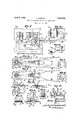
- Fig. l is a semi-diagrammatic side view of an engine showing the keeper tongs and catch pan in use, the tongs being shown in side elevation and in a position to attach a keeper to a valve stem; and the pan is arranged to catch the halves of the keeper in the event they are accidentally displaced from the tongs while being placed in use.
- Fig. 2 is a plan view of the tongs showing a keeper connected to it; also indicating by dotted lines an open position of the tongs.
- Fig. 3 is a view from the underside of the tongs.
- Fig. 4 is a slightly enlarged sectional View on the line lr-l, Fig.
- Fig. 5 is a plan view of the left hand portion of Fig. 4, showing the arrangement of the teeth on one of the movable jaws for gripping the half portion of the keeper.
- Fig, 6 is a cross section on line 6 6, Fig. 2, showing the tongues on the tong arms extended under the slide bars to aid in holding those parts together, also showing about the normal position of the half parts of the keepei ⁇ when seated on the tongs.
- Fig. 7 is another cross section on the line 7 7 of Fig.
- Fig. 8 is a view analogous to Fig. showing the keeper fully seated on the valve stem and the tongs removed; and also showing by dotted lines the spring'retainer seated on the keeper.
- Fig. 9 is afragmental combined plan and edge view of the jaw end ot one oi' the arms and the teeth ier engaging the keeper.
- Fig. 10 is also a fraginental combined plan and edge view of the jaw end of one of the slide bars orcompanion part to the parts shown in Fig. 9, showing the teeth 'for engaging the keeper.
- Fig. 11 is a greatly enlarged section'on the line 11-11 ot Fig. 5, showing a half part of a keeper seated on the slide bar and gripped by the inclined curved teeth of the fixed and movable jaws.
- Fig. 12 is a top plan of the keeper catch an.
- p Fig. 13 is a section through line 13-13 of Fig. 12.
- the tongs 15 includes the arms 16 and 17 that have overlapping side iianges 18, 19 that are connected by a pivot bolt 20'. T he arms and integral side flanges as well as the tongues 21 are stamped out of suitable sheet metal and preferably the handle ends 22 oi' these arms are given a quarter turn so they are arranged at right angles relative to the arms.
- the tongues 21 which also are integral with the arms are bent downward and then under the arms so as to hold the slide bars 23 with their integral flanges 24 engaged with the outside edges oi' the arms so they are slidable between the tongues.
- the bars 23 have vturned down projections 26 at their rear ends by which the bars are manually moved against the tension of a spring 27.
- This spring normally moves the jaws 28 of the slide bars toward the jaws 29 on the arms 16, 17, and the projections form iinger holds for manually separating the jaws so the half parts oi-a keeper can be attached-to or detached from the tongs.
- the spring 27 holds the side flanges 24 of the bars 23 engaged with the rear tongues 21 of the arms as indicated by dotted lines in Fig. 3.
- Another spring 30 is arranged on the pivot bolt 2O for normally forcing the handles 22 apart so that the side teeth 32 of the jaws 29 'engage one another and also side teeth 31V oit the jaws 28 on the rslide bars abuttingly engage, as best shown in Figs. 2 and 3.
- the movable jaws 28 are provided with inclined curved end teeth 33 that are arranged to tit over the curved base edge portion of the split coneshaped keeper 311 and by means of the spring 27 the teeth 23 are actuated to force the ialves of the keeper against the side teeth 32 and also the curved inclined end teeth 132 et the jaw 28 so the keeper is very iirmly secured to the tongs so the latter can be handled relatively. roughly without displacing the parts of the keeper.
- the parts of the keeper are secured to the aws so the tongs can be manipulated to separate them a suicient distance to place them on valve stem, as previously stated.
- the keeper 34 is a hollow split tapered cone plug having an inwardly extended annular iiange 35 that is seated in an annular rec-ess 36 on the lower end ot a valve stein 37 so as to support the retainer disk 38 in a position to hold the valve spring 39 under tension.
- rFliese parts are all old and are only shown in the drawings for the purpose of illustrating the vuse of the tongs and catch pan.
- the slide bars 23 are cut away at 50 to forni a clearance for the lower end of the valve stem 37' when the keeper is moved into place, see ⁇ Figs. 3, l and 10.
- the keeper catch pan 40 is split centrally through its bottom and ends, and at one ot its ends are overlapping bearing extensions that are pivotally connected by the bolt l2 so that the parts a and b of the pan can be separated so as to lit the pan around the valve push rods 43.
- the open position of the pan is partly indicated by dotted lines in Fig. 12; and inA Fig. 1 it is shown in use.
- the iront or pivoted end of the pan is bent down as best shown in Fig. 13 so that it will not be in the way ot the keeper tongs when placing a keeper on a valve stem.
- the pan is easily attached and detached from and to the push rods and is very effective in catching Vthe parts of the keeper in the event they are displaced fromI the tongs while being placed on the valve stem; and also when these keepers are removed from the stem tor any purpose the pan will prevent them from falling into the crank case in the event they fall out of the mechanics hand when 'the valve spring retainer is lifted against the tension of the valve spring 39.
- rllie engine 200 is fragmen'tally shown in 1, it being understood that the tongue vand catch pan can be used to install and change the keepers on all types of engines using them.
- Fig. 1 I show the lett hand spring 37 and associated parts in about a normal position, the other two springs 37 to the right of it being lifted or elevated so that the keepers can be attached to the valve stems 37.
- the spring 37 is lifted by the tool 100 and held in an elevated position while the keeper 34 is removed and replaced for purposes well known in the art, such as removing the valves for grinding and replacing them.
- the keeper 34 When the keeper 34 is to be placed on the valve stem its halves are seated on the tongs with their base edges gripped by the jaws 28 and 29. Then the tongs are manipulated to place the keeper on the valve stem so its annular iiange 35 is seated in the annular groove- 86 in the stem where the keeper is held until the tool 100 is operated to release the spring 37 the tension of which will force the retainer 38 down over the tapered keeper and hold it'securely on the stem; and also the keeper in turn will hold the retainer in position to support the spring 37 under proper tension.
- a keeper tongs including a pair of arms having overlapping side extensions, a bolt pivot-ally connecting said extensions, handles on said arms, slide bars supported under said arms, projections to said bars arranged adjacent said handles, a spring on said bolt for engaging said projections and normally forcing said bars toward said handles, and aws at the ends of said arms and bars for engaging and detachably holding a keeper so it -an be placed on a valve stem.
- a keeper tongs including a pair of arms having overlapping side extensions, a bolt for pivotally connecting said extensions so the ends of said arms can be moved toward and from one another, handles to said arms, slide bars arranged under said arms, tongues and side flanges for slidably connecting said bars to said arms, projections to said bars arranged adjacent said handles, a spring for engaging said projections and normally forcing said bars toward said handles, and jaws at the ends of said arms and bars arranged to engage and hold the base edge portion of a keeper so it can be secured to a valve stem.
- a keeper tongs including a pair of arms having overlapping side extensions, a bolt pivot-ally connecting said extensions so the ends of said arms can be moved toward or from one another, handles integral with said arms, slide bars arranged under said arms, tongues integral with said arms and edge flanges integral with said bars for slidably holding said bars under said arms, projections that can be manually manipulated to move said hars endwise of said arms, a spring on said bolt for engaging said projections and normally forcing said bars endwise toward said handles, another spring on said bolt for normally forcing said handles apart, and jaws at the ends of said arms and bars for engaging and holding a keeper so it can be placed on a valve stem.
- a keeper tongs including a pair of arms having overlapping side extensions, a bolt pivotally connecting said extensions so the ends of said arms can be moved toward or from one another, handles integral with said arms, slide bars arranged under said arms, tongues integral with said arms and edge flanges integral with said bars for slidably holding said bars under said arms, projections that can be manually manipulated to move said bars endwise of said arms, a spring on said bolt for engaging said projections and normally forcing said bars endwise toward said handles, another spring on said bolt for normally forcing said handles apart, jaws at the ends of said arms and bars, and teeth on said jaws for engaging and holding a keeper so it can be placed on a valve stem. 5.
- a keeper tongs including arms, overlapping side extensions integral with said arms, a bolt extending through said side extensions for pivotally securing said arms together, jaws integral with said arms, side teeth integral with said aws, handles on said arms, bars slidably connected to said arms, jaws on said bars, a spring for normally forcing the aws on said bars toward the jaws on said arms, side teeth on the jaws of said slide bars arranged to be moved longitudinally toward or away from the side teeth on the jaws of said arms, and curved inclined end teeth to the jaws of said slide bars adapted to be fitted over and around the base edge portion of a split conical keeper.
Landscapes
- Engineering & Computer Science (AREA)
- Mechanical Engineering (AREA)
- Load-Engaging Elements For Cranes (AREA)
Description
` pl'll 5, 1932- .1. KAMlNsKl TONGS FOR PLACING KEEPERS ON VALVE STEMS Filed oct. 6, 195o Patented Apr. 5,A 1932 UNITED STATES JOHN KAMINSKI, F PASADENA, CALIFORNIA Y' TONGS'FOR PLACING KEEPERS ON VALVE `SJ'JEMS Application led October G, 1930. Serial No. 486,531.
This invention relates to appliances for placing cone-shaped split 'keepers on valve stems to support their retainer disks in position to hold the valve springs under tension and to prevent loss of the keeper parts while being placed in use, and, as is well known, the placing of'these keepers on valve stems has heretofore been considered a tedious dificult task requiring both time and labor to accomplish, and the principal object of this invention is to save time and labor in seating the keepers by providing a keeper tongs that will aid greatly in connecting the keeper to a valve stem without loss of time or arduous and tedious labor. To that end I provide a keeper tongs adapted to grip and hold the base edges of the keeper parts so they can be separated by manipulation of the tongs a suiiicient distance to extend them up and over the lower end of a valve stem into a seating position. In other words the halves of the keepers are detachably secured to the arms of the tongs so they can be easily handled while being moved into place on the valve stem.
Another object of the invention is to provide a simple means for preventing the parts of the cone shaped keeper from being lost or displaced from the tongs while being placed in use, and to that end I provide the tongs with jaws at an end of each arm having teeth arranged around a keeper seat that are adapted to engage and hold the halves of the keeper so they cannot easily be displaced from the tongs even when roughly handled. In other words the teeth of the jaws grip the base of the cone shaped keeper so iirmly that the tongs can be turned upside down and thro-wn around roughly without displacing its parts, yet the firm gripping of the jaws on the keeper parts does not prevent an easy separation of the tongs from the keeper whenl the latter advertently they are displaced from the tongs or from the valve stem whilebeing placed in use, or disconnected from the stem, and to that end I provide a keeper catch pan that in the operation of placing the keeper on or removing it from the valve stem is a companion part with the tongs in saving time and labor. In use it is adapted to be iitted around the valve stem push rod so it is under the keeper and arranged to catch its partsif they fall toward the crank case either while being placed on or removed from the valve stem.
Features of invention are shown in the'construction, combination and arrangement of the parts wherebyT a keeper tongs and catch pan are provided that are adapted to save time and labor in attaching and detaching the keeper parts to and 'rom a valve stem, which appliances are also easy to construct, assemble and operate, and durable in use.
Other objects, advantages and 'features of invention may appear from the accompanying drawings, the subjoined detailed description and the appended claims.
The accompanying drawings illustrate the invention, in which Fig. l is a semi-diagrammatic side view of an engine showing the keeper tongs and catch pan in use, the tongs being shown in side elevation and in a position to attach a keeper to a valve stem; and the pan is arranged to catch the halves of the keeper in the event they are accidentally displaced from the tongs while being placed in use. Fig. 2 is a plan view of the tongs showing a keeper connected to it; also indicating by dotted lines an open position of the tongs. Fig. 3 is a view from the underside of the tongs. Fig. 4 is a slightly enlarged sectional View on the line lr-l, Fig. 2, showing a half part of a` keeper with its base portion secured to the tongs and also `showing by dotted lines the lower slide bar moved to an open position so the half part of the keeper can be released from or seated on the tongs. Fig. 5 is a plan view of the left hand portion of Fig. 4, showing the arrangement of the teeth on one of the movable jaws for gripping the half portion of the keeper. Fig, 6 is a cross section on line 6 6, Fig. 2, showing the tongues on the tong arms extended under the slide bars to aid in holding those parts together, also showing about the normal position of the half parts of the keepei` when seated on the tongs. Fig. 7 is another cross section on the line 7 7 of Fig. 2 showing the side iianges on the slide bars that engage the edges of the arms to keep those parts together, also illustrating by dotted lines the position of the halt parts of the keeper before being placed on the valve stem and by full lines showing them arranged on the valve stem ready to receive the valve spring retainer that is shown by dotted lines above the keeper. v j
Fig. 8 is a view analogous to Fig. showing the keeper fully seated on the valve stem and the tongs removed; and also showing by dotted lines the spring'retainer seated on the keeper. Fig. 9 is afragmental combined plan and edge view of the jaw end ot one oi' the arms and the teeth ier engaging the keeper. Fig. 10 is also a fraginental combined plan and edge view of the jaw end of one of the slide bars orcompanion part to the parts shown in Fig. 9, showing the teeth 'for engaging the keeper. Fig. 11 is a greatly enlarged section'on the line 11-11 ot Fig. 5, showing a half part of a keeper seated on the slide bar and gripped by the inclined curved teeth of the fixed and movable jaws.
Fig. 12 is a top plan of the keeper catch an. p Fig. 13 is a section through line 13-13 of Fig. 12.
The tongs 15 includes the arms 16 and 17 that have overlapping side iianges 18, 19 that are connected by a pivot bolt 20'. T he arms and integral side flanges as well as the tongues 21 are stamped out of suitable sheet metal and preferably the handle ends 22 oi' these arms are given a quarter turn so they are arranged at right angles relative to the arms.
The tongues 21 which also are integral with the arms are bent downward and then under the arms so as to hold the slide bars 23 with their integral flanges 24 engaged with the outside edges oi' the arms so they are slidable between the tongues.
The bars 23 have vturned down projections 26 at their rear ends by which the bars are manually moved against the tension of a spring 27. This spring normally moves the jaws 28 of the slide bars toward the jaws 29 on the arms 16, 17, and the projections form iinger holds for manually separating the jaws so the half parts oi-a keeper can be attached-to or detached from the tongs. Normally the spring 27 holds the side flanges 24 of the bars 23 engaged with the rear tongues 21 of the arms as indicated by dotted lines in Fig. 3. v
Another spring 30 is arranged on the pivot bolt 2O for normally forcing the handles 22 apart so that the side teeth 32 of the jaws 29 'engage one another and also side teeth 31V oit the jaws 28 on the rslide bars abuttingly engage, as best shown in Figs. 2 and 3.
In addition to the side teeth 31 the movable jaws 28 are provided with inclined curved end teeth 33 that are arranged to tit over the curved base edge portion of the split coneshaped keeper 311 and by means of the spring 27 the teeth 23 are actuated to force the ialves of the keeper against the side teeth 32 and also the curved inclined end teeth 132 et the jaw 28 so the keeper is very iirmly secured to the tongs so the latter can be handled relatively. roughly without displacing the parts of the keeper.
Also the parts of the keeper are secured to the aws so the tongs can be manipulated to separate them a suicient distance to place them on valve stem, as previously stated.
The keeper 34, as is well known, is a hollow split tapered cone plug having an inwardly extended annular iiange 35 that is seated in an annular rec-ess 36 on the lower end ot a valve stein 37 so as to support the retainer disk 38 in a position to hold the valve spring 39 under tension. rFliese parts are all old and are only shown in the drawings for the purpose of illustrating the vuse of the tongs and catch pan.
The slide bars 23 are cut away at 50 to forni a clearance for the lower end of the valve stem 37' when the keeper is moved into place, see` Figs. 3, l and 10.
rThe keeper catch pan 40 is split centrally through its bottom and ends, and at one ot its ends are overlapping bearing extensions that are pivotally connected by the bolt l2 so that the parts a and b of the pan can be separated so as to lit the pan around the valve push rods 43. The open position of the pan is partly indicated by dotted lines in Fig. 12; and inA Fig. 1 it is shown in use. Preferably the iront or pivoted end of the pan is bent down as best shown in Fig. 13 so that it will not be in the way ot the keeper tongs when placing a keeper on a valve stem.
The pan is easily attached and detached from and to the push rods and is very effective in catching Vthe parts of the keeper in the event they are displaced fromI the tongs while being placed on the valve stem; and also when these keepers are removed from the stem tor any purpose the pan will prevent them from falling into the crank case in the event they fall out of the mechanics hand when 'the valve spring retainer is lifted against the tension of the valve spring 39.
1n Fig. 1 I show the lett hand spring 37 and associated parts in about a normal position, the other two springs 37 to the right of it being lifted or elevated so that the keepers can be attached to the valve stems 37.
The means `for lifting the springs 37 to release the keepers or place them on the valve 'stems is old in the art and form no part of this invention, however a tool 100 indicated by dotted lines in Fig. l is shown for the purpose of illustration.
In operation the spring 37 is lifted by the tool 100 and held in an elevated position while the keeper 34 is removed and replaced for purposes well known in the art, such as removing the valves for grinding and replacing them.
When the keeper 34 is to be placed on the valve stem its halves are seated on the tongs with their base edges gripped by the jaws 28 and 29. Then the tongs are manipulated to place the keeper on the valve stem so its annular iiange 35 is seated in the annular groove- 86 in the stem where the keeper is held until the tool 100 is operated to release the spring 37 the tension of which will force the retainer 38 down over the tapered keeper and hold it'securely on the stem; and also the keeper in turn will hold the retainer in position to support the spring 37 under proper tension.
Also as the retainer descends on the keeper it will strike the upwardly extending teeth on the jaws 28, 29 and automatically displace the tongs from the keeper. It is understood, however, that the slide bars 2B can be moved by means heretofore described to release the tongs from the keeper when so desired.
I claim as my invention:
l. A keeper tongs including a pair of arms having overlapping side extensions, a bolt pivot-ally connecting said extensions, handles on said arms, slide bars supported under said arms, projections to said bars arranged adjacent said handles, a spring on said bolt for engaging said projections and normally forcing said bars toward said handles, and aws at the ends of said arms and bars for engaging and detachably holding a keeper so it -an be placed on a valve stem.
2. A keeper tongs including a pair of arms having overlapping side extensions, a bolt for pivotally connecting said extensions so the ends of said arms can be moved toward and from one another, handles to said arms, slide bars arranged under said arms, tongues and side flanges for slidably connecting said bars to said arms, projections to said bars arranged adjacent said handles, a spring for engaging said projections and normally forcing said bars toward said handles, and jaws at the ends of said arms and bars arranged to engage and hold the base edge portion of a keeper so it can be secured to a valve stem.
3. A keeper tongs including a pair of arms having overlapping side extensions, a bolt pivot-ally connecting said extensions so the ends of said arms can be moved toward or from one another, handles integral with said arms, slide bars arranged under said arms, tongues integral with said arms and edge flanges integral with said bars for slidably holding said bars under said arms, projections that can be manually manipulated to move said hars endwise of said arms, a spring on said bolt for engaging said projections and normally forcing said bars endwise toward said handles, another spring on said bolt for normally forcing said handles apart, and jaws at the ends of said arms and bars for engaging and holding a keeper so it can be placed on a valve stem.
fl. A keeper tongs including a pair of arms having overlapping side extensions, a bolt pivotally connecting said extensions so the ends of said arms can be moved toward or from one another, handles integral with said arms, slide bars arranged under said arms, tongues integral with said arms and edge flanges integral with said bars for slidably holding said bars under said arms, projections that can be manually manipulated to move said bars endwise of said arms, a spring on said bolt for engaging said projections and normally forcing said bars endwise toward said handles, another spring on said bolt for normally forcing said handles apart, jaws at the ends of said arms and bars, and teeth on said jaws for engaging and holding a keeper so it can be placed on a valve stem. 5. A keeper tongs including arms, overlapping side extensions integral with said arms, a bolt extending through said side extensions for pivotally securing said arms together, jaws integral with said arms, side teeth integral with said aws, handles on said arms, bars slidably connected to said arms, jaws on said bars, a spring for normally forcing the aws on said bars toward the jaws on said arms, side teeth on the jaws of said slide bars arranged to be moved longitudinally toward or away from the side teeth on the jaws of said arms, and curved inclined end teeth to the jaws of said slide bars adapted to be fitted over and around the base edge portion of a split conical keeper.
In witness whereof, I have hereunto affixed my signature.
JOHN KAMINSKI.
Priority Applications (1)
| Application Number | Priority Date | Filing Date | Title |
|---|---|---|---|
| US486531A US1852580A (en) | 1930-10-06 | 1930-10-06 | Tongs for placing keepers on valve stems |
Applications Claiming Priority (1)
| Application Number | Priority Date | Filing Date | Title |
|---|---|---|---|
| US486531A US1852580A (en) | 1930-10-06 | 1930-10-06 | Tongs for placing keepers on valve stems |
Publications (1)
| Publication Number | Publication Date |
|---|---|
| US1852580A true US1852580A (en) | 1932-04-05 |
Family
ID=23932255
Family Applications (1)
| Application Number | Title | Priority Date | Filing Date |
|---|---|---|---|
| US486531A Expired - Lifetime US1852580A (en) | 1930-10-06 | 1930-10-06 | Tongs for placing keepers on valve stems |
Country Status (1)
| Country | Link |
|---|---|
| US (1) | US1852580A (en) |
Cited By (3)
| Publication number | Priority date | Publication date | Assignee | Title |
|---|---|---|---|---|
| US2521842A (en) * | 1949-04-11 | 1950-09-12 | Foster Frank | Primer catcher |
| US2641148A (en) * | 1948-02-24 | 1953-06-09 | Arthur Evan Meirion | Appliance for fitting valve spring collets |
| US4865498A (en) * | 1988-05-19 | 1989-09-12 | Schoettler Frank J | Electrode dressing tool |
-
1930
- 1930-10-06 US US486531A patent/US1852580A/en not_active Expired - Lifetime
Cited By (3)
| Publication number | Priority date | Publication date | Assignee | Title |
|---|---|---|---|---|
| US2641148A (en) * | 1948-02-24 | 1953-06-09 | Arthur Evan Meirion | Appliance for fitting valve spring collets |
| US2521842A (en) * | 1949-04-11 | 1950-09-12 | Foster Frank | Primer catcher |
| US4865498A (en) * | 1988-05-19 | 1989-09-12 | Schoettler Frank J | Electrode dressing tool |
Similar Documents
| Publication | Publication Date | Title |
|---|---|---|
| US1657348A (en) | Tool | |
| US1852580A (en) | Tongs for placing keepers on valve stems | |
| US2708592A (en) | Tongs | |
| US2091500A (en) | Valve tool | |
| US2196117A (en) | Fish grapple | |
| US1503898A (en) | Clean-out tool for furnaces | |
| US1775022A (en) | Tool for holding bushings for valve stems | |
| US1536601A (en) | Tool for inserting split sleeves | |
| US1874257A (en) | Placing tool for automobile motor valve shoes | |
| US1814107A (en) | Rail tongs | |
| US1651998A (en) | Valve-spring lifter | |
| US1608883A (en) | Valve tool | |
| US1791961A (en) | Valve lifter | |
| US2016078A (en) | Lamp wrench | |
| US1892900A (en) | Valve puller | |
| US1321594A (en) | Gripping-tongs | |
| US1571195A (en) | Valve-spring lifter | |
| US2519024A (en) | Overhead valve spring remover | |
| US1713762A (en) | Valve-spring compressor | |
| US1718841A (en) | Valve-spring compressor | |
| US2096391A (en) | Article pick-up device | |
| US2318866A (en) | Valve keeper tool | |
| US2623768A (en) | Box and container handle | |
| US1951970A (en) | Valve keeper inserting tool | |
| US1608176A (en) | Valve-lifting tool |