US1852577A - Fastening mechanism for car doors - Google Patents
Fastening mechanism for car doors Download PDFInfo
- Publication number
- US1852577A US1852577A US24778828A US1852577A US 1852577 A US1852577 A US 1852577A US 24778828 A US24778828 A US 24778828A US 1852577 A US1852577 A US 1852577A
- Authority
- US
- United States
- Prior art keywords
- door
- bar
- seal
- movement
- keeper
- Prior art date
- Legal status (The legal status is an assumption and is not a legal conclusion. Google has not performed a legal analysis and makes no representation as to the accuracy of the status listed.)
- Expired - Lifetime
Links
- 230000007246 mechanism Effects 0.000 title description 10
- 230000001012 protector Effects 0.000 description 20
- 238000010276 construction Methods 0.000 description 3
- 230000004048 modification Effects 0.000 description 3
- 238000012986 modification Methods 0.000 description 3
- 238000013459 approach Methods 0.000 description 2
- 230000006378 damage Effects 0.000 description 2
- 208000014674 injury Diseases 0.000 description 2
- 238000007789 sealing Methods 0.000 description 2
- 208000012260 Accidental injury Diseases 0.000 description 1
- 208000027418 Wounds and injury Diseases 0.000 description 1
- 230000003028 elevating effect Effects 0.000 description 1
- 230000002452 interceptive effect Effects 0.000 description 1
Images

Classifications
-
- E—FIXED CONSTRUCTIONS
- E05—LOCKS; KEYS; WINDOW OR DOOR FITTINGS; SAFES
- E05B—LOCKS; ACCESSORIES THEREFOR; HANDCUFFS
- E05B83/00—Vehicle locks specially adapted for particular types of wing or vehicle
- E05B83/02—Locks for railway freight-cars, freight containers or the like; Locks for the cargo compartments of commercial lorries, trucks or vans
-
- Y—GENERAL TAGGING OF NEW TECHNOLOGICAL DEVELOPMENTS; GENERAL TAGGING OF CROSS-SECTIONAL TECHNOLOGIES SPANNING OVER SEVERAL SECTIONS OF THE IPC; TECHNICAL SUBJECTS COVERED BY FORMER USPC CROSS-REFERENCE ART COLLECTIONS [XRACs] AND DIGESTS
- Y10—TECHNICAL SUBJECTS COVERED BY FORMER USPC
- Y10S—TECHNICAL SUBJECTS COVERED BY FORMER USPC CROSS-REFERENCE ART COLLECTIONS [XRACs] AND DIGESTS
- Y10S292/00—Closure fasteners
- Y10S292/30—Latch and handle
-
- Y—GENERAL TAGGING OF NEW TECHNOLOGICAL DEVELOPMENTS; GENERAL TAGGING OF CROSS-SECTIONAL TECHNOLOGIES SPANNING OVER SEVERAL SECTIONS OF THE IPC; TECHNICAL SUBJECTS COVERED BY FORMER USPC CROSS-REFERENCE ART COLLECTIONS [XRACs] AND DIGESTS
- Y10—TECHNICAL SUBJECTS COVERED BY FORMER USPC
- Y10S—TECHNICAL SUBJECTS COVERED BY FORMER USPC CROSS-REFERENCE ART COLLECTIONS [XRACs] AND DIGESTS
- Y10S292/00—Closure fasteners
- Y10S292/32—Freight car door fasteners
-
- Y—GENERAL TAGGING OF NEW TECHNOLOGICAL DEVELOPMENTS; GENERAL TAGGING OF CROSS-SECTIONAL TECHNOLOGIES SPANNING OVER SEVERAL SECTIONS OF THE IPC; TECHNICAL SUBJECTS COVERED BY FORMER USPC CROSS-REFERENCE ART COLLECTIONS [XRACs] AND DIGESTS
- Y10—TECHNICAL SUBJECTS COVERED BY FORMER USPC
- Y10S—TECHNICAL SUBJECTS COVERED BY FORMER USPC CROSS-REFERENCE ART COLLECTIONS [XRACs] AND DIGESTS
- Y10S292/00—Closure fasteners
- Y10S292/46—Sliding door fasteners
-
- Y—GENERAL TAGGING OF NEW TECHNOLOGICAL DEVELOPMENTS; GENERAL TAGGING OF CROSS-SECTIONAL TECHNOLOGIES SPANNING OVER SEVERAL SECTIONS OF THE IPC; TECHNICAL SUBJECTS COVERED BY FORMER USPC CROSS-REFERENCE ART COLLECTIONS [XRACs] AND DIGESTS
- Y10—TECHNICAL SUBJECTS COVERED BY FORMER USPC
- Y10T—TECHNICAL SUBJECTS COVERED BY FORMER US CLASSIFICATION
- Y10T292/00—Closure fasteners
- Y10T292/08—Bolts
- Y10T292/096—Sliding
- Y10T292/1006—Gravity actuated
- Y10T292/1007—Operating means
- Y10T292/101—Cam
Definitions
- This invention relates to fastening mechanisms for car doors and has for its primary object the provision of a rugged and simple mechanism for automatically fastening and sealing a. car door or the like in predetermined position.
- Another object of this invention is to provide a fastening mechanism for car doors or the like which may be released with a maximum of convenience as by a longitudinal pull on the handle to open or close the door.
- Fig. l is a fragmentary longitudinal view of the side of a car embodying this invention
- Fig. 2 is an enlarged fragmentary sectional view taken at the line 22 of Fig. 1, and
- Fig. 3 is a similar view of a modification.
- Fig. l is a fragmentary, longitudinal View of car embodying another form of this invention.
- Fig. 5 is a fragmentary horizontal section taken at the line 55 of Fig. 4.
- Fig. 6 is a fragmentary vertical section taken at the line 66 of Fig. i.
- Fig. 7 is a fragmentary longitudinal view of the side of a car embodying still another form of this invention.
- Fig. 8 is a plan view, partly in section, of the form shown in ig.
- Fig. 9 is a section taken at the line 99 of Fig. 7. 7
- numeral 4 represents a car door hung from a track 5 above anti-frictional bearing 6 thereon, the track being arranged in the usual manner along the upper edge of the car.
- the door is slidable on the track 5 from a position along the outside of the wall 7 of the car to and from closed position as shown in Fig. 1.
- a vertically slidable fastening bar 8 is car- Serial No. erase.
- This bar is normally carried in a predetermined vertical position such that during the extreme opening or closing movements of the door said bar engages with keepers 11 and 12, respectively, to automatically fasten the door in opened or closed position.
- the keepers 11 and 12 are secured to. the car sill near the extreme positions of the door and are provided with inclined edges 13 and 14:, respectively, upon whiclrthe lower end of the bar 8 is adapted to ride when the door approaches the corresponding extreme position.
- the keepers 11 and 12 are also provided with abrupt shoulders 15 and 16, respectively, adjoining the respective inclined edges so that as the door is moved to closed position the lower end of the bar 8 will ride up on the inclined edge 14 and drop down again to the left of said edge viewing 1, the downward movement of said bar being limited by a handle 17 as will be presently explained.
- the shoulder 75 16 will then be in a position to engage the lower end of the bar 8 to prevent the door from being opened without lifting said bar.
- the bar 8 is normally carried in its downward position as viewed in Fig. 1 with an outwardly projecting portion 18 at its upper end in engagement with the upper edge of the handle bar 17, the latter acting as a 0 stop to limit the downward movement of said bar 8.
- the bar 1.7 is provided with an integral handle portion 19 adapted to be manually grasped and moved. longitudinally to open or close the door.
- the bar 17 is carried at its opposite ends in hollow brackets 21 and 22, respectively, secured to the car door.
- the ends of the bar 17 are each provided with a depending V-shaped portion 23 which normally rests in a corresponding 'V-shaped groove 24 in the corresponding one of the brackets 21 and 22. WVhen the handle 19 is grasped and a longitudinal pull to the right exerted thereon viewing Fig. 1 to open the door, the bar 17 will slide to the right, the V-shaped portions 23 riding up on the sides of the corresponding grooves 24, thus elevating said bar and lifting the locking bar.
- an angle bar preferably a Z-bar at its lower edge with a depending flange 26 adapted to ride in a. longitudinal groove 27 formed in each of the keepers 11 and 12 inwardly of their respective outer edges.
- Fig. 3 is shown a modificationembodying a bottom hung door instead of a top hung door as in the first embodiment.
- a bottom track 28 is carried by brackets 29' secured to the car sill, the door being provided with an inwardly extending Z'bar 31 by means of which the door is supported above the added friction bearing 32 on said track.
- the fastening mechanism is substantially similar to that of the first embodiment, the exception being that the fastening bar here designated as 33 is provided with an inwardly extending portion 34, the inner end of which is adapted to engage with a keeper 35.
- the keeper 35 is similar to the keepers in the first embodiment but instead of being secured to the car sill is secured to the edge of the track 28.
- v bar 31 is provided with a depending'portion 36 which extends below the inner edge of the track 28 to prevent outward lateral movement of the door.
- An angle bar 37 is also provided having a depending flange extending below the outer edge of the track to prevent inward lateral movement of the door.
- a locking and sealing mechanism including a hasp 38 may also be provided for the door as illustrated and described in connection with my co-pending application Serial No. 233,540 filed November 16, 1927.
- numeral 39 represents a car door similar to the door 4 and carried on a track 41 above anti-frictional bearings 42 thereon the track in this instance being arranged al'ongthe lower edge of'the car.
- the door is slidable on the track 41 from a position along the outside of the wall of the car to and from closed position in the same manner as the door 4.
- the door may, of course, be atop hung door as in the previous embodiment.
- a vertically slidable locking bar 43 is supported. between vertically spaced straps 44 and 45 respectively attached to the outside of the door.
- the bar 43 isadapted to ride verticallyin the straps 44 and 45 upon engagement with the inclined edge 46 of a keeper 47 similar to the keeper 12 and is also adaptedto d'ropinto a recess 48 in said keeper adjoining said edge.
- the keeperv 47 is provided with spaced shoulders 49 at opposite sides ofsaid'recess-48 in position to be abutted by opposite sides respectively of the lower end'of the bar 43.
- the bar 43 lik-e the bar 8 is normally carried the handle bar 17 which acts as a stop to limit thed'ownwar-d movement of'said bar 43'.
- handle 17 is substantially the same as-in the previous embodiment and acts with respect to the bar 43 in substantially the same manner as the handle 17 in the previousembodiment acts withrespect to t'he bar 8.
- the bar 43 is provided at its upper end with anoutwardlyproject ing flange 52 which when the bar is in downward position lies between projecting flanges 53 on the strap 45.
- the flanges 53 are provided with depending lugs respectively between which is hinged a seal protector 55.
- the seal protector 55', the flange 52 and the two flanges 53 are provided with aligned apertures for accommodating a seal.
- This seal protector is outwardly weighted so that when the car is not sealed it automatically drops to abut the upper surface 50 of the projection 51. This surface is concave and cooperates with a convex surface 56 on the protector 55 whereby said protector will be automatically forced outwardly when the bar is raised.
- the upper or free end of the protector 55 is provided with a lateral projection 57 which when the door is sealed isadapted to extend over the top of the bar 43 and flange 52 for positively preventing upward movement of said bar.
- the apertures 58 in the flanges 53 and the aperture 59 in the seal protector 55 for the seal are of uniform size but the aperture 61 in the flange 52 for the seal is considerably longer and wider than said apertures 58 and 59 in order that a limited amount of in and out or vertical movement of the bar 43 within the strap may be had without injury to the seal.
- the contour of the upper end of the flange 52 with respect to the lower surface of the projection 57 is such that should there be any upward movement of the fastening bar the tendency is to force the seal protector inwardly rather than outwardly thus preventing damage to the seal.
- numeral 62 represents a car door mounted in substantially the same manner as the door 39 just described.
- a vertically sliding locking bar 63 is carried in vertically spaced straps 64 and 65 which are substantially the same as straps 4:4 and 45 respectively.
- the bar 63 is adapted to cooperate with a keeper 66 which is substantially the same as the keeper 47 in the previous embodiment.
- the principal difference between this embodiment and the previous one is that the bar 63 is shaped to provide an outwardly spaced portion 67 in the form of a handle, the upper side of which at its juncture with the upper portion of said bar presents a concave surface 68.
- the lower side of the handle 67 forms a shoulder 69 adapted to abut the upper edge of the strap 64 to limit the downward movement of the bar.
- a seal protector 71 substantially the same as the seal protector 55 cooperates with the upper end of the bar 63 and the strap 65 substantially the same as in the previous embodiment. In this instance when the door is fastened and the protector 71 is in inoperative position the contour of the free end of said protector is adapted to cooperate with the surface 68 in the same manner as the surface 50 in the previous embodiment was adapted to cooperate with the seal protector.
- said member being provided with an opening adapted to receive a seal therethrough, means for supporting a seal in operative rela tion with respect to said opening and a seal protector pivotally carried by the same part which carries said member adapted to be actuated to and from operative position whereby it may engage with said member for positively preventing movement thereof away from said keeper, said protector being provided with openings in alignment with the 3 opening-in said member when said member and protector are in there respective operative positions.
Landscapes
- Specific Sealing Or Ventilating Devices For Doors And Windows (AREA)
Description
April 5, 1932. E. F. JAGER FASTENING MECHANISM FOR CAR DOORS Filed Jan. 19. 1928 3 Sheets-Sheet April 5, 1932. E. F. JAGER FASTENING MECHANISM FOR CAR DOORS Filed Jan. 19; 1928 3 Sheets-Sheet 2 Ja an/Z 07:
April 5, 1932. E. F. JAGER FASTENING MECHANISM FOR CAR DOORS Filed Jan. 19, 1928 5 Sheets-Sheet 3 Jzuerzar I fjgefi Patented Apr. 5, 1932 since FASTENIIII'G E'IQEQHMIIEIE FDR CAR DOGRS Application filed January 19, 1928.
This invention relates to fastening mechanisms for car doors and has for its primary object the provision of a rugged and simple mechanism for automatically fastening and sealing a. car door or the like in predetermined position.
Another object of this invention is to provide a fastening mechanism for car doors or the like which may be released with a maximum of convenience as by a longitudinal pull on the handle to open or close the door.
It is also an object of this invention to improve generally upon a construction illustrat ed and described in Patent No. 1,430,555 of October 3, 1922.
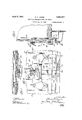
Other and further objects of this invention will be apparent as the same becomes better understood from an examination of the specilication and claims in connection with the accompanying drawings wherein Fig. l is a fragmentary longitudinal view of the side of a car embodying this invention,
Fig. 2 is an enlarged fragmentary sectional view taken at the line 22 of Fig. 1, and
Fig. 3 is a similar view of a modification.
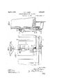
Fig. l is a fragmentary, longitudinal View of car embodying another form of this invention.
Fig. 5 is a fragmentary horizontal section taken at the line 55 of Fig. 4.
Fig. 6 is a fragmentary vertical section taken at the line 66 of Fig. i.
Fig. 7 is a fragmentary longitudinal view of the side of a car embodying still another form of this invention.
Fig. 8 is a plan view, partly in section, of the form shown in ig.
Fig. 9 is a section taken at the line 99 of Fig. 7. 7
Referring to the drawings more particularly numeral 4 represents a car door hung from a track 5 above anti-frictional bearing 6 thereon, the track being arranged in the usual manner along the upper edge of the car. The door is slidable on the track 5 from a position along the outside of the wall 7 of the car to and from closed position as shown in Fig. 1. p
A vertically slidable fastening bar 8 is car- Serial No. erase.
ried in a bracket 9 attached to the outside of the door 4: intermediate the side edges thereof for automatically fastening said door in open or closet position. This bar is normally carried in a predetermined vertical position such that during the extreme opening or closing movements of the door said bar engages with keepers 11 and 12, respectively, to automatically fasten the door in opened or closed position. The keepers 11 and 12 are secured to. the car sill near the extreme positions of the door and are provided with inclined edges 13 and 14:, respectively, upon whiclrthe lower end of the bar 8 is adapted to ride when the door approaches the corresponding extreme position. The keepers 11 and 12 are also provided with abrupt shoulders 15 and 16, respectively, adjoining the respective inclined edges so that as the door is moved to closed position the lower end of the bar 8 will ride up on the inclined edge 14 and drop down again to the left of said edge viewing 1, the downward movement of said bar being limited by a handle 17 as will be presently explained. The shoulder 75 16 will then be in a position to engage the lower end of the bar 8 to prevent the door from being opened without lifting said bar.
Similarly when the door approaches its final movement to open position the lower end of the bar 8 will ride up on the edge 13 and subsequently drop down in position to engage the shoulder 15 for preventing closing of the door without again lifting said bar. 85
The bar 8 is normally carried in its downward position as viewed in Fig. 1 with an outwardly projecting portion 18 at its upper end in engagement with the upper edge of the handle bar 17, the latter acting as a 0 stop to limit the downward movement of said bar 8.
The bar 1.7 is provided with an integral handle portion 19 adapted to be manually grasped and moved. longitudinally to open or close the door. The bar 17 is carried at its opposite ends in hollow brackets 21 and 22, respectively, secured to the car door. The ends of the bar 17 are each provided with a depending V-shaped portion 23 which normally rests in a corresponding 'V-shaped groove 24 in the corresponding one of the brackets 21 and 22. WVhen the handle 19 is grasped and a longitudinal pull to the right exerted thereon viewing Fig. 1 to open the door, the bar 17 will slide to the right, the V-shaped portions 23 riding up on the sides of the corresponding grooves 24, thus elevating said bar and lifting the locking bar.
-' lowermost position causing the bar 8 to move downwardly in position where it may on gage with the keeper 13 to fasten the door in open position.
When it is desired to close the door again 7 the reverse of the aforedescribed operation will take place, a pull to the left on the han- 'dle 19 causing the bar 17 to similarly rise and release the fastening bar 8.
In order to prevent lateral movement of l i the door the same is provided with an angle bar preferably a Z-bar at its lower edge with a depending flange 26 adapted to ride in a. longitudinal groove 27 formed in each of the keepers 11 and 12 inwardly of their respective outer edges.
In Fig. 3is shown a modificationembodying a bottom hung door instead of a top hung door as in the first embodiment. In such a modification a bottom track 28 is carried by brackets 29' secured to the car sill, the door being provided with an inwardly extending Z'bar 31 by means of which the door is supported above the added friction bearing 32 on said track. In this modification the fastening mechanism is substantially similar to that of the first embodiment, the exception being that the fastening bar here designated as 33 is provided with an inwardly extending portion 34, the inner end of which is adapted to engage with a keeper 35. The keeper 35 is similar to the keepers in the first embodiment but instead of being secured to the car sill is secured to the edge of the track 28. In this case the v bar 31 is provided with a depending'portion 36 which extends below the inner edge of the track 28 to prevent outward lateral movement of the door. An angle bar 37 is also provided having a depending flange extending below the outer edge of the track to prevent inward lateral movement of the door.
A locking and sealing mechanism including a hasp 38 may also be provided for the door as illustrated and described in connection with my co-pending application Serial No. 233,540 filed November 16, 1927.
It will be apparent that the aforedescribed fastening mechanism is very simple,
rugged and fool proof, it operating automatically to fasten the door in open or closed position thus preventing any possibility of accident by the door suddenly opening or closing and the fastening mechanism being automatically released when the handle is actuated to open or close the door.
Referring to the form of the invention illustrated in Figs. 4 to 6 inclusive numeral 39 represents a car door similar to the door 4 and carried on a track 41 above anti-frictional bearings 42 thereon the track in this instance being arranged al'ongthe lower edge of'the car. The door is slidable on the track 41 from a position along the outside of the wall of the car to and from closed position in the same manner as the door 4. The door may, of course, be atop hung door as in the previous embodiment.
A vertically slidable locking bar 43 is supported. between vertically spaced straps 44 and 45 respectively attached to the outside of the door. The bar 43 isadapted to ride verticallyin the straps 44 and 45 upon engagement with the inclined edge 46 of a keeper 47 similar to the keeper 12 and is also adaptedto d'ropinto a recess 48 in said keeper adjoining said edge. The keeperv 47 is provided with spaced shoulders 49 at opposite sides ofsaid'recess-48 in position to be abutted by opposite sides respectively of the lower end'of the bar 43. Thus when the bar 43 has dropped down into the recess 48,. the door will be prevented from movement in either direction relative to the keeper.
The bar 43 lik-e the bar 8 is normally carried the handle bar 17 which acts as a stop to limit thed'ownwar-d movement of'said bar 43'. The
handle 17 is substantially the same as-in the previous embodiment and acts with respect to the bar 43 in substantially the same manner as the handle 17 in the previousembodiment acts withrespect to t'he bar 8.
In this embodiment the bar 43 is provided at its upper end with anoutwardlyproject ing flange 52 which when the bar is in downward position lies between projecting flanges 53 on the strap 45. The flanges 53 are provided with depending lugs respectively between which is hinged a seal protector 55. The seal protector 55', the flange 52 and the two flanges 53 are provided with aligned apertures for accommodating a seal. This seal protector is outwardly weighted so that when the car is not sealed it automatically drops to abut the upper surface 50 of the projection 51. This surface is concave and cooperates with a convex surface 56 on the protector 55 whereby said protector will be automatically forced outwardly when the bar is raised.
The upper or free end of the protector 55 is provided with a lateral projection 57 which when the door is sealed isadapted to extend over the top of the bar 43 and flange 52 for positively preventing upward movement of said bar.
The apertures 58 in the flanges 53 and the aperture 59 in the seal protector 55 for the seal are of uniform size but the aperture 61 in the flange 52 for the seal is considerably longer and wider than said apertures 58 and 59 in order that a limited amount of in and out or vertical movement of the bar 43 within the strap may be had without injury to the seal.
The contour of the upper end of the flange 52 with respect to the lower surface of the projection 57 is such that should there be any upward movement of the fastening bar the tendency is to force the seal protector inwardly rather than outwardly thus preventing damage to the seal.
It will be apparent that by use of the construction just described any accidental injury to the seal is prevented.
Referring to the form of the invention described in Figs. 7 to 9 inclusive numeral 62 represents a car door mounted in substantially the same manner as the door 39 just described. A vertically sliding locking bar 63 is carried in vertically spaced straps 64 and 65 which are substantially the same as straps 4:4 and 45 respectively. The bar 63 is adapted to cooperate with a keeper 66 which is substantially the same as the keeper 47 in the previous embodiment. The principal difference between this embodiment and the previous one is that the bar 63 is shaped to provide an outwardly spaced portion 67 in the form of a handle, the upper side of which at its juncture with the upper portion of said bar presents a concave surface 68. The lower side of the handle 67 forms a shoulder 69 adapted to abut the upper edge of the strap 64 to limit the downward movement of the bar. A seal protector 71 substantially the same as the seal protector 55 cooperates with the upper end of the bar 63 and the strap 65 substantially the same as in the previous embodiment. In this instance when the door is fastened and the protector 71 is in inoperative position the contour of the free end of said protector is adapted to cooperate with the surface 68 in the same manner as the surface 50 in the previous embodiment was adapted to cooperate with the seal protector.
The operation and advantages of the aforedescribed constructions will be apparent without further description.
I am aware that many details may be varied without departing from the principles of this invention and I therefore do not wish to be limited to the details shown or described.
I claim:
1. The combination with a slidable door adapted to be operated across an opening in a wall to open and close said opening, of a fastening member carried by said door, a handle member for said door operatively connected to said fastening member, means attached to the door for supporting the handle for limited bodily sliding movement with respect to said door and in a direction parallel to the movement of said door, cam surfaces on said handle member and cooperating cam surfaces on said supporting means whereby when a pull-is exerted on the handle to slidably move the door said handle will automatically actuate said fastening member.
2. The combination with a slidable door adapted to be operated across an opening in a wall, of a fastening member, a keeper adapted to cooperate with said member to fasten said door in a predetermined position in its path of movement, a pivotally mounted seal protector for positively preventing movement of said fastening member in a direction away from said keeper, said keeper being provided with an inclined edge for automatically actuating said member, a projection on said member by means of which the same may be manually actuated provided with an in- 1T5 clined surface adapted to cooperate with said seal protector when the latter is in inoperative position in the path of said projection for preventing the seal protector from interfering with the movement of said member and means for supporting a seal in operative relation with respect to said seal protector when the same is in operative position whereby it is prevented from being released without breaking the seal.
3. The combination with a pair of relatively movable parts comprising a slidable door and a wall provided with an opening across which the door is adapted to be 0perated, of a fastener member slidably carried by one of said parts, a keeper carried by the other part and adapted to cooperate with said member to fasten said door in a predetermined position in its path of movement,
said member being provided with an opening adapted to receive a seal therethrough, means for supporting a seal in operative rela tion with respect to said opening and a seal protector pivotally carried by the same part which carries said member adapted to be actuated to and from operative position whereby it may engage with said member for positively preventing movement thereof away from said keeper, said protector being provided with openings in alignment with the 3 opening-in said member when said member and protector are in there respective operative positions.
4. The combination with a pair of relatively movable parts comprising a slidable door'and a wall provided with an opening across which the door is adapt-ed'to'be operated, of a fastener member carried 'by one of the parts, a keeper adapted to cooperate with said member to fasten said door in a predetermined position in its path of'movement, means carried by the same part which carries the fastener member for positively preventing movement of said member in a direction away from said keeper, and means also carried by the same part which carries the fastener member for supporting a, seal inoperative relation with respect to said first: means whereby the same is prevented from being released without breaking the seal, said member being provided with means adapted to also receive the seal whereby. it is prevented from being moved away from said keeper without breaking the seal even if the first means is broken.
5. The combination with a slidabie door adapted to be operated across an opening in awall to open and close said opening, of a fastening member carried by the door, a keeper adapted to be engaged by said member to fasten said door and a handle mounted on said door for limited bodily sliding movement with respect to said door and in a direction parallel to the movement of said door, said handle being operatively connected to said fastening member and cooperating means on said handle and fastening member for disengaging said fastening member from said keeper upon sliding movement of said iandle with respect to said door.
6; The combination with a slidable door adapted to be operated across an opening in a wall, of a slidable fastener member carried by the door, a keeper adapted to cooperate with said member to fasten said door in a predetermined position in its. path of movement, a separate handle mounted for movements relatively to said door and said fastener member and operatively associated with said fastener member for moving said memher out of engagement with said keeper, a pivotally mounted element arranged to positively prevent movement of said fastening member, and means for supporting a seal in operative relation with respect to said fastening element and said pivotal means whereby said fastening element and said pivotal means are prevented from being released without breaking the seal.
7. The combination with a slidable door adapted to be operated across an opening in a wall, of a slidable fastener member carried by the door, a keeper adapted to cooperate with said member to fasten said door in a predetermined position in its path of movement, pivotally mounted means for positively preventing movement of the fastening memher in a direction away from said keeper when in operative position and arranged to be engaged by said fastener member when in inoperative position, and means for supporting a seal in operative relation with respect to said first means when in operative position whereby the same is prevented from being released'without breaking the seal.
'8. The combination with aslidable door adapted to be operated across an opening in a wall of a slidable fastener member carried by the door, a keeper adapted to cooperate with said member to fasten said door in a predetermined position in its path of movement, means for positively preventing movement of the fastening member in a direction away from said keeper, and means for supporting a sealin operative relation with respect to said first means whereby the same is prevented from being released without breaking the seal, said member being provided with means adapted to receive the seal, whereby it is prevented from being move away from said keeper without breaking the seal even if the first means is broken.
9. The combination with a slidable door adapted to be operated across an opening in a wall to open and close said opening, of a fastening member carried by said door, a handle member for said door operatively connected to said fastening member, means attached to the door for supporting the handle for limited bodily sliding movement with respect to said door and in a direction parallel to the movement of said door, and cooperat ing cam surfaces on said handle member and supporting means whereby when a pull is exerted on the handle to slidably move the door said handle will be moved-in a direction parallel to the movement of the door and in a direction transverse to the movement of the door to automatically actuate said fastening member.
In witness of the foregoing I afiixmy signature.
EARL F. JAGER-i
Priority Applications (1)
| Application Number | Priority Date | Filing Date | Title |
|---|---|---|---|
| US24778828 US1852577A (en) | 1928-01-19 | 1928-01-19 | Fastening mechanism for car doors |
Applications Claiming Priority (1)
| Application Number | Priority Date | Filing Date | Title |
|---|---|---|---|
| US24778828 US1852577A (en) | 1928-01-19 | 1928-01-19 | Fastening mechanism for car doors |
Publications (1)
| Publication Number | Publication Date |
|---|---|
| US1852577A true US1852577A (en) | 1932-04-05 |
Family
ID=22936372
Family Applications (1)
| Application Number | Title | Priority Date | Filing Date |
|---|---|---|---|
| US24778828 Expired - Lifetime US1852577A (en) | 1928-01-19 | 1928-01-19 | Fastening mechanism for car doors |
Country Status (1)
| Country | Link |
|---|---|
| US (1) | US1852577A (en) |
-
1928
- 1928-01-19 US US24778828 patent/US1852577A/en not_active Expired - Lifetime
Similar Documents
| Publication | Publication Date | Title |
|---|---|---|
| US1852577A (en) | Fastening mechanism for car doors | |
| US2816431A (en) | Chain lock for closures | |
| US478748A (en) | Grain-car door | |
| GB2101192A (en) | Securing devices for closures | |
| US1701516A (en) | Storm-window fixture | |
| US1141286A (en) | Sash-lock. | |
| US1411625A (en) | Sliding-door controller | |
| US1914194A (en) | Automobile box car door post | |
| US1025134A (en) | Sash-locking device. | |
| US1793125A (en) | Door-operating mechanism | |
| US1441349A (en) | Door structure | |
| US901419A (en) | Sliding-door fastener. | |
| US1383548A (en) | Combination hinge and catch for automobile-doors | |
| US1552718A (en) | Window | |
| US1494110A (en) | Automatic weather strip for closures | |
| US1067547A (en) | Car-door. | |
| US882014A (en) | Grain-door for cars. | |
| US1263756A (en) | Disappearing sash for porch constructions. | |
| US1466900A (en) | Elevator-door lock | |
| US1290462A (en) | Sliding-door closing and locking device. | |
| US1823453A (en) | Door operating and locking device | |
| US890690A (en) | Sliding-door fastener. | |
| US1638088A (en) | Window-sash fastener | |
| US1042326A (en) | Sliding-door lock. | |
| US802041A (en) | Car-door fastener. |