US1852563A - Clay gxtn carkiage and locking means - Google Patents
Clay gxtn carkiage and locking means Download PDFInfo
- Publication number
- US1852563A US1852563A US1852563DA US1852563A US 1852563 A US1852563 A US 1852563A US 1852563D A US1852563D A US 1852563DA US 1852563 A US1852563 A US 1852563A
- Authority
- US
- United States
- Prior art keywords
- gun
- carriage
- furnace
- clay
- locking
- Prior art date
- Legal status (The legal status is an assumption and is not a legal conclusion. Google has not performed a legal analysis and makes no representation as to the accuracy of the status listed.)
- Expired - Lifetime
Links
- 239000004927 clay Substances 0.000 title description 35
- 238000010079 rubber tapping Methods 0.000 description 32
- 238000007599 discharging Methods 0.000 description 27
- 239000012530 fluid Substances 0.000 description 19
- NJPPVKZQTLUDBO-UHFFFAOYSA-N novaluron Chemical compound C1=C(Cl)C(OC(F)(F)C(OC(F)(F)F)F)=CC=C1NC(=O)NC(=O)C1=C(F)C=CC=C1F NJPPVKZQTLUDBO-UHFFFAOYSA-N 0.000 description 3
- 238000010276 construction Methods 0.000 description 2
- 230000005611 electricity Effects 0.000 description 1
- 239000002184 metal Substances 0.000 description 1
- 230000000717 retained effect Effects 0.000 description 1
- 239000000725 suspension Substances 0.000 description 1
Images
Classifications
-
- C—CHEMISTRY; METALLURGY
- C21—METALLURGY OF IRON
- C21B—MANUFACTURE OF IRON OR STEEL
- C21B7/00—Blast furnaces
- C21B7/12—Opening or sealing the tap holes
-
- F—MECHANICAL ENGINEERING; LIGHTING; HEATING; WEAPONS; BLASTING
- F27—FURNACES; KILNS; OVENS; RETORTS
- F27B—FURNACES, KILNS, OVENS OR RETORTS IN GENERAL; OPEN SINTERING OR LIKE APPARATUS
- F27B1/00—Shaft or like vertical or substantially vertical furnaces
- F27B1/10—Details, accessories or equipment specially adapted for furnaces of these types
- F27B1/21—Arrangements of devices for discharging
Definitions
- An important object of the invention is to provide a compact carriage structure socured to and suspended from the end of a boom which is supported for swinging movement, and the suspension of the gun from the carriage structure by means of rollers I thereon engaging in guideways or rails on the carriage structure, with the guideways or rails so designed that the gun may first be dipped down into an inclined position and then shifted axially to carry its nozzle into the blast furnace tapping hole.
- a further object of the invention is to provide fluid pressure operating means for swinging the carriage, and fluid pressure operated means for shifting the gun on the carriage.
- Another object is to provide improved locking means for locking the carriage relative to the furnace after the carriage has been swung to position the gun for projection into the tapping hole.
- Figure 2 is an enlarged plan view of the structure shown in Figure 1;
- Figure 3 is an enlarged section on plane III'III of Figure 2;
- Figure 4 is a plan View, partly in section, of the gun barrel locking mechanism.
- Figure 5 is a more or less diagrammatic view showing a modified arrangement for swinging the carriage supporting boom.
- I have shown the gun structure associated with a furnace F having the usual tapping hole in front of which extends the runner trough 11 for receiving the discharged molten metal, the tapping hole and the running trough being below the level of a supporting floor 12 on which the gun structure is mounted and operated.
- the -clay discharge drive for the gun G may be by steam, electricity, or otherwise.
- the structure shown is more or less like that 5 of the gun disclosed in my copending application, Serial No. 450,373, filed May 7, 1930. Briefly, the structure shown comprises the barrel or cylinder 13 having the discharge nozzle 14 and provided with one or more 80 clay filling hoppers 15.
- the gun piston (not shown) may be connected to a gear rack or screw shaft (not shown) operated by a suitable motor 16 and a reduction gearing train 17.
- the gun is supported by the carriage structure C which is suspended from the end of the boom 18 projecting from the vertical frame 19 rotatably mounted on a base 20 concentric with a vertical stationary 90 shaft 21.
- the carriage frame is U-shaped in plan view (Fig. 2) and comprises the parallel side walls 22 and 28 joined at the front by a yoke wall 24.
- the sidewalls are rigidly secured 95 to the boom to thus support the carriage frame, and a bracket structure 25 extending from the gun G is secured to the side walls to suspend the gun below the carriage frame.
- the outer end of the bracket 25 has arms 26 y and 27 extending upwardly therefrom and receiving a shaft 28 having at its ends rollers 29 and 29' engaging respectively in the guideways 30 and 30 in the outer ends of the walls 22 and 23 of the carriage frame.
- At the inner end of the gun supporting bracket 25 are the arms 31 and 32 receiving the shaft 33 which at its outer ends has the rollers 34 and 34 engaging respectively in the guideways 35 and 35' in the walls 22 and 23 along the front part of the carriage structure.
- the front ends of the guideways 30 and 35 incline downwardly and are at the same angle relative to the horizontal.
- the rear ends of the guideways or channels 35 and 35 incline upwardly and the rear ends of the channels 30 and 30 curve gradually downwardly.
- the rollers will be at the outer ends of the guideways so that the gun will be substantially horizontal.
- the gun is shown in dis charging position and after a discharging operation the gun is first shifted back to normal position on the carriage and then the boom is swung around substantially 180-degrees to bring the gun into position over the floor so that a fresh charge of clay may be loaded therein.
- I preferably provide pneumatic means for controlling the swinging movement of the boom, and also for shifting the gun on the carriage.
- the means shown for shifting the gun on the carriage comprises a fiuidcylinder 36 from whose piston 37 the piston rod 38 extends outwardly through the cylinder head to be connected to the shaft 28 by means of a suitable clamp 39.
- the cylinder At its inner end the cylinder has the lugs 40 extending therefrom which receive a pivot pin 42 carried by the bracket 43 secured on the yoke 24 of the carriage frame.
- Pipes 44 and 45 communicating with the outer and inner ends respectively of the cylinder are connected with a suitable source of fluid under pressure (not shown).
- a suitable source of fluid under pressure may be a compressed air reservoir (not shown) and the flow of the fluid may be controlled by means of suitable valve mechanism (not shown).
- the means for controlling the swing of the boom comprises a fluid pressure cylinder 46 secured in position on top of the boom.
- the piston rod 47 extending from the, piston 48 carries at its outer end a rack bar 49 whose teeth mesh with a gear wheel 50 which is rigidly secured to the upper end of the shaft 21.
- the gear Upon reciprocation of the piston and the'rack bar, the gear will form a stationary track for the rack bar and the boom will be swung.
- a guide bracket 51 extending from the boom will guide the rack bar and hold it in mesh with the gear.
- the cylinder 46 communicates at its ends with pipes 52 and 53' connected with the source of fluid under pressure.
- the piston will be forced toward the opposite end of the cylinder and the cooperation of the rack bar with the gear will cause the boom to swing in clockwise direction to carry the suspended gun and carriage away from the furnace tapping hole.
- the piston will be forced to the opposite direction and the boom will be swung to align the gun with the tapping hole and if the pressure is then maintained the boom and carriage will be held in such position.
- Figure 5 shows a modified arrangement for swinging the boom.
- a sheave 54 is secured on top of the boom supporting body 19 concentric with the swing axis and a cable 55 extend around the sheave.
- a piston 55 Secured to the cable is a piston 55 traveling in a cylinder 56 whose ends are adapted for connection with the source of fluid under pressure through pipes 57 and 58.
- the cable travels around an idler sheave 59 and the cylinder structure may be supported at a point remote from the furnace.
- the piston Upon admission of fluid into either end of the cylinder the piston will be forced through the cylinder and the cable will travel and cause rotation of the sheave 54 and of the body 19 so that the boom is swung to position the gun carriage where desired.
- the means shown for locking the carriage comprises two spaced apart brackets 60 and 61 secured to and extending outwardy from the furnace wall and having their vertical outer wall sections connected by inner and outer plates 62 and 63to form a vertical channel or groove 6% for receiving the inner leg 65 of a U-shaped lock bolt 66.
- a bracket 67 is secured to and extends forwardly from the gun carriage frame and has the vertical passage 68 through which the leg 69 of the lock bolt may extend behind the front wall 7 O of the bracket.
- a cable 71 is secured to the bolt and extends to a point remote from the furnace so that it may be pulled to raise the bolt to release its shorter leg 69 from the gun carriage bracket 67, the other leg 65 of the bolt being longer so that it will remain in its channel 64 to guide the bolt into the channel 68 when it is again desired to lock the carriage to the furnace.
- This locking means securely holds the carriage after it has been swung to bring the gun into position to be shifted towards the tapping hole.
- the means for locking the gun barrel in charging position comprises a rectangular plate or block 72 secured on the ledge 73 of the furnace above the tapping hole 10. At its outer end the block has the longitudinal passageway 74 for receiving the upper end of the locking lug 7 5 extending upwardly from the gun barrel adjacent to the nozzle 14.
- This lug may be castintegral with the gun barrel or may be a separate piece rigidly secured thereto as by means of bolts 76.
- the upper part of the lug which enters the passageway 74 has ratchet teeth 77 and 77 along its opposite side.
- the plate 72 has openings 78 and 7 8' in its opposite sides communicating with the passageway 74 and in these openings are pivoted the pawls 79 and 79 respectively for cooperating at their inner ends with the ratchet teeth on the lug 75. Behind these side openings 78 and 78 the plate 72 has vertical projections 80 and 80 which journal a cross shaft 81 having secured at its opposite ends arms 82, 82 which extend downwardly along the outer sides of the plate 72. Links 83 and 83 are pivoted at one end to the ends of'the arms 82.
- the shaft 80 has a weight arm 84 secured thereto and extending forwardly therefrom and bearing a weight 85.
- This weight tends to swing the arm 84 down to cause rotation of the shaft 81 to swing the arms 82. 82 inwardly so that the links 83, 83 will tend to swing the pawls with their inner ends in the path of or against the ratchet teeth on the lug 75.
- the pawls will extend transversely of the passageway 74 and then when the gun is shifted into discharging position the lug 75 will enter the passageway and will encounter the pawls and will deflect them against the pressure of the weight, the weight then holding the pawls against the. teeth so as to prevent retraction of the lug and consequently the gun so that the gun barrel will then be rigidly held and locked in discharging position.
- Unlocking may be accomplished by pull on the cable 86' which is connected to the outer end of the weight supporting arm 84 and under such pull the shaft 81 will be rotated to cause outward shift of the links 83-83 and retraction of the inner ends of the pawls from the ratchet teeth so that the gun may then be withdrawn from the tapping hole.
- the cable 86 may be manipulated at a point remote from the furnace and after release of the cable the weight 85 will again become effective to cause the pawls to be extended transversely of the passageway 74 for the reception'of the lug 75 when the gun is-again shifted into discharging position.
- I thus provide a compact and efficient clay gun outfit for blast furnaces which can be operated to powerfully and quickly bring the gun barrel into alignment with the tapping hole and then operated to shift the gun barrel into discharging position, the manually operable means then rigidly locking the carriage to the furnace and the automatic means rigidly locking the gun barrel itself to the furnace, so that the furnace back pressure is fully resisted.
- the pneumatic operating means for the boom and the gun are of simple construction and can be very economically built. By maintaining the pressure in these fluid operated devices, they will assist the other locking means in holding the carriage and the gun rigid during discharge of the gun.
- clay gun structure the combination of a clay gun, a supporting carriage on which said gun is shiftable from a loading position to a discharging position, fluid pressure controlled means for moving said carriage, and fluid pressure operated means for shifting said gun on said carriage.
- clay gun structure the combination of a clay gun, a supporting carriage for the gun on which the gun is supported to be shifted into loading or discharging position, and a fluid pressure operated means comprising a cylinder mounted on said carriage and having a piston connected with said gun for shifting said gun on said carriage.
- clay gun structure the combination of a clay gun, a supporting carriage therefor having guide rails, a supporting bracket for' the gun having rollers engaging said rails whereby to suspend said gun from said carriage, and means for shifting said gun on said carriage comprising a cylinder member and a piston member, one of said members being supported by the carriage and the other member being connected to said gun, and means for conducting fluid under pressure to the cylinder member.
- fluid pressure operable mechanism comprising a cylinder having a piston and a piston rod extending therefrom, said cylinder being rigidy secured relative to said boom, and a rack bar connected to the piston rod and meshing with said gear whereby upon relative movement of said rack bar and gear said boom will be swung.
- clay gun mechanism the combination of a boom structure mounted on a vertical axis for lateral swing, a carriage supported by said boom, a clay gun supported by said carriage, a sheave secured to said boom structure concentric with its swing axis, a cable looped around said sheave, a piston secured to said cable, a cylinder for said piston, and means for supplying fluid under pressure to said cylinder for shifting the piston therein to cause travel of said cable and swing of said boom structure.
- clay gun structure the combination of a clay gun, a supporting carriage for the gun on which the gun is shiftable into loading or discharge position, and fiuidpressure operated means between said gun and carriage for shifting said gun on said carriage.
Landscapes
- Engineering & Computer Science (AREA)
- Chemical & Material Sciences (AREA)
- Mechanical Engineering (AREA)
- General Engineering & Computer Science (AREA)
- Manufacturing & Machinery (AREA)
- Materials Engineering (AREA)
- Metallurgy (AREA)
- Organic Chemistry (AREA)
- Spray Control Apparatus (AREA)
Description
April 5, 1932. A. F. GIE'SE, JR
OLAY GUN CARRIAGE AND LOCKING MEANS Filed March '26, 1931 2 Sheets-Sheet l April 5, 1932. A. F. G'lESE JR 1,852,563 CLAY GUN CARRIAGE AND LOCKING MEANS Filed March 26, 1951 2 Sheets-Sheet 2 I 2. 79 fi is Patented Apr. 5, 1932 UNITED STATES PATENT OFFICE AUGUST F. GIESE, JR., 015 GARY, INDIANA CLAY GUN CARRIAGE AND LOCKING MEANS Application filed March 26, 1931.
gun into position in front of the tapping holes to be thereafter shifted to carry its nozzle into the tapping hole and to then be operated to discharge its load of clay into the hole.
An important object of the invention is to provide a compact carriage structure socured to and suspended from the end of a boom which is supported for swinging movement, and the suspension of the gun from the carriage structure by means of rollers I thereon engaging in guideways or rails on the carriage structure, with the guideways or rails so designed that the gun may first be dipped down into an inclined position and then shifted axially to carry its nozzle into the blast furnace tapping hole.
A further object of the invention is to provide fluid pressure operating means for swinging the carriage, and fluid pressure operated means for shifting the gun on the carriage.
Another object is to provide improved locking means for locking the carriage relative to the furnace after the carriage has been swung to position the gun for projection into the tapping hole. I
It is a still further object of this inventio to provide locking means, preferably automatically controlled, for locking the gun barrel directly relative to the furnace after it has been projected into the tapping hole so that the carriage and the gun barrel will be rigidly held in place against the back pressure from the furnace during discharge of clay from the guninto the tapping hole.
The above enumerated and other features of the invention are ipcorporated in the Serial No. 525,443.
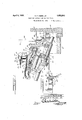
structure shown on the drawings, in which drawings Figure 1 is a side elevation of the gun structure with part of the furnace to which it is applied shown in vertical cross section; I
Figure 2 is an enlarged plan view of the structure shown in Figure 1;
Figure 3 is an enlarged section on plane III'III of Figure 2;
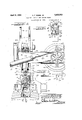
Figure 4 is a plan View, partly in section, of the gun barrel locking mechanism; and
Figure 5 is a more or less diagrammatic view showing a modified arrangement for swinging the carriage supporting boom.
I have shown the gun structure associated with a furnace F having the usual tapping hole in front of which extends the runner trough 11 for receiving the discharged molten metal, the tapping hole and the running trough being below the level of a supporting floor 12 on which the gun structure is mounted and operated.
The -clay discharge drive for the gun G may be by steam, electricity, or otherwise. The structure shown is more or less like that 5 of the gun disclosed in my copending application, Serial No. 450,373, filed May 7, 1930. Briefly, the structure shown comprises the barrel or cylinder 13 having the discharge nozzle 14 and provided with one or more 80 clay filling hoppers 15. The gun piston (not shown) may be connected to a gear rack or screw shaft (not shown) operated by a suitable motor 16 and a reduction gearing train 17.
The gun is supported by the carriage structure C which is suspended from the end of the boom 18 projecting from the vertical frame 19 rotatably mounted on a base 20 concentric with a vertical stationary 90 shaft 21.
The carriage frame is U-shaped in plan view (Fig. 2) and comprises the parallel side walls 22 and 28 joined at the front by a yoke wall 24. The sidewalls are rigidly secured 95 to the boom to thus support the carriage frame, and a bracket structure 25 extending from the gun G is secured to the side walls to suspend the gun below the carriage frame. The outer end of the bracket 25 has arms 26 y and 27 extending upwardly therefrom and receiving a shaft 28 having at its ends rollers 29 and 29' engaging respectively in the guideways 30 and 30 in the outer ends of the walls 22 and 23 of the carriage frame. At the inner end of the gun supporting bracket 25 are the arms 31 and 32 receiving the shaft 33 which at its outer ends has the rollers 34 and 34 engaging respectively in the guideways 35 and 35' in the walls 22 and 23 along the front part of the carriage structure.
The front ends of the guideways 30 and 35 incline downwardly and are at the same angle relative to the horizontal. The rear ends of the guideways or channels 35 and 35 incline upwardly and the rear ends of the channels 30 and 30 curve gradually downwardly. Normally the rollers will be at the outer ends of the guideways so that the gun will be substantially horizontal. Upon movement of the gun on the carriage towards the furnace it will first be dipped rapidly downwardly and then will be shifted axially toward the tapping hole to project its discharge nozzle into the hole, the gun being then in position for the ejection of the clay therefrom to plug the tapping hole.
On the drawings the gun is shown in dis charging position and after a discharging operation the gun is first shifted back to normal position on the carriage and then the boom is swung around substantially 180-degrees to bring the gun into position over the floor so that a fresh charge of clay may be loaded therein. I preferably provide pneumatic means for controlling the swinging movement of the boom, and also for shifting the gun on the carriage. The means shown for shifting the gun on the carriage comprises a fiuidcylinder 36 from whose piston 37 the piston rod 38 extends outwardly through the cylinder head to be connected to the shaft 28 by means of a suitable clamp 39. At its inner end the cylinder has the lugs 40 extending therefrom which receive a pivot pin 42 carried by the bracket 43 secured on the yoke 24 of the carriage frame. Pipes 44 and 45 communicating with the outer and inner ends respectively of the cylinder are connected with a suitable source of fluid under pressure (not shown). Such source may be a compressed air reservoir (not shown) and the flow of the fluid may be controlled by means of suitable valve mechanism (not shown). Referring to Figure 1, when fluid under pressure is admitted through the pipe 45 the piston will be forced outwardly in the cylinder and by the connection of its piston rod with the roller supporting shaft on the gun supporting bracket 25, the gun will be shifted outwardly to its normal position; Upon admission of fluid under pressure through the pipe 44 the piston will'travel in the opposite direction and the gun will be shifted down into the discharging position and if the pressure is then maintained the gun will be held in this position. The pivotal connection of the cylinder with'the carriage frame permits swing of the cylinder during the shifting of the gun on the carriage.
As shown in Figures 1 and 2, the means for controlling the swing of the boom comprises a fluid pressure cylinder 46 secured in position on top of the boom. The piston rod 47 extending from the, piston 48 carries at its outer end a rack bar 49 whose teeth mesh with a gear wheel 50 which is rigidly secured to the upper end of the shaft 21. Upon reciprocation of the piston and the'rack bar, the gear will form a stationary track for the rack bar and the boom will be swung. A guide bracket 51 extending from the boom will guide the rack bar and hold it in mesh with the gear.
The cylinder 46 communicates at its ends with pipes 52 and 53' connected with the source of fluid under pressure. Referring to Figure 2, if fluid under pressure is admitted thru the pipe 53 the piston will be forced toward the opposite end of the cylinder and the cooperation of the rack bar with the gear will cause the boom to swing in clockwise direction to carry the suspended gun and carriage away from the furnace tapping hole. If fluid under pressure is admitted through the pipe 52 the piston will be forced to the opposite direction and the boom will be swung to align the gun with the tapping hole and if the pressure is then maintained the boom and carriage will be held in such position.
Figure 5 shows a modified arrangement for swinging the boom. A sheave 54 is secured on top of the boom supporting body 19 concentric with the swing axis and a cable 55 extend around the sheave. Secured to the cable is a piston 55 traveling in a cylinder 56 whose ends are adapted for connection with the source of fluid under pressure through pipes 57 and 58. The cable travels around an idler sheave 59 and the cylinder structure may be supported at a point remote from the furnace. Upon admission of fluid into either end of the cylinder the piston will be forced through the cylinder and the cable will travel and cause rotation of the sheave 54 and of the body 19 so that the boom is swung to position the gun carriage where desired.
It is very important that the gun be rigidly held in discharging position while the clay is discharged therefrom under heavy pressure against the counter pressure of the furnace. I. therefore, not only provide means for rigidly locking the carriage relative to the furnace but also means for locking the gun barrel itself relative to the furnace. The means shown for locking the carriage comprises two spaced apart brackets 60 and 61 secured to and extending outwardy from the furnace wall and having their vertical outer wall sections connected by inner and outer plates 62 and 63to form a vertical channel or groove 6% for receiving the inner leg 65 of a U-shaped lock bolt 66. A bracket 67 is secured to and extends forwardly from the gun carriage frame and has the vertical passage 68 through which the leg 69 of the lock bolt may extend behind the front wall 7 O of the bracket. A cable 71 is secured to the bolt and extends to a point remote from the furnace so that it may be pulled to raise the bolt to release its shorter leg 69 from the gun carriage bracket 67, the other leg 65 of the bolt being longer so that it will remain in its channel 64 to guide the bolt into the channel 68 when it is again desired to lock the carriage to the furnace. This locking means securely holds the carriage after it has been swung to bring the gun into position to be shifted towards the tapping hole.
The means for locking the gun barrel in charging position comprises a rectangular plate or block 72 secured on the ledge 73 of the furnace above the tapping hole 10. At its outer end the block has the longitudinal passageway 74 for receiving the upper end of the locking lug 7 5 extending upwardly from the gun barrel adjacent to the nozzle 14. This lug may be castintegral with the gun barrel or may be a separate piece rigidly secured thereto as by means of bolts 76. When the gun is shifted axially to project its nozzle into the tapping hole the lug 75 will enter the passageway 7 1 of the plate 72, the outer end of the plate being inclined upwardly as shown in Figure 1 to be parallel with the gun barrel at this time.
The upper part of the lug which enters the passageway 74 has ratchet teeth 77 and 77 along its opposite side. The plate 72 .has openings 78 and 7 8' in its opposite sides communicating with the passageway 74 and in these openings are pivoted the pawls 79 and 79 respectively for cooperating at their inner ends with the ratchet teeth on the lug 75. Behind these side openings 78 and 78 the plate 72 has vertical projections 80 and 80 which journal a cross shaft 81 having secured at its opposite ends arms 82, 82 which extend downwardly along the outer sides of the plate 72. Links 83 and 83 are pivoted at one end to the ends of'the arms 82. 82 respectively and at their other ends the links are pivoted to the outer ends of the pawls 79 and 7 9 respectively. Between the bearing extensions 80, 80 the shaft 80 has a weight arm 84 secured thereto and extending forwardly therefrom and bearing a weight 85.
This weight tends to swing the arm 84 down to cause rotation of the shaft 81 to swing the arms 82. 82 inwardly so that the links 83, 83 will tend to swing the pawls with their inner ends in the path of or against the ratchet teeth on the lug 75. Before the gun is shifted into the tapping hole the pawls will extend transversely of the passageway 74 and then when the gun is shifted into discharging position the lug 75 will enter the passageway and will encounter the pawls and will deflect them against the pressure of the weight, the weight then holding the pawls against the. teeth so as to prevent retraction of the lug and consequently the gun so that the gun barrel will then be rigidly held and locked in discharging position. The locking operation of the gun barrel to the furnace is thus automaticall v accomplished. Unlocking may be accomplished by pull on the cable 86' which is connected to the outer end of the weight supporting arm 84 and under such pull the shaft 81 will be rotated to cause outward shift of the links 83-83 and retraction of the inner ends of the pawls from the ratchet teeth so that the gun may then be withdrawn from the tapping hole. The cable 86 may be manipulated at a point remote from the furnace and after release of the cable the weight 85 will again become effective to cause the pawls to be extended transversely of the passageway 74 for the reception'of the lug 75 when the gun is-again shifted into discharging position.
I thus provide a compact and efficient clay gun outfit for blast furnaces which can be operated to powerfully and quickly bring the gun barrel into alignment with the tapping hole and then operated to shift the gun barrel into discharging position, the manually operable means then rigidly locking the carriage to the furnace and the automatic means rigidly locking the gun barrel itself to the furnace, so that the furnace back pressure is fully resisted. The pneumatic operating means for the boom and the gun are of simple construction and can be very economically built. By maintaining the pressure in these fluid operated devices, they will assist the other locking means in holding the carriage and the gun rigid during discharge of the gun.
As changes in construction, arrangement and operation may be made without departing from the scope and principles of the invention, I do not desire to be limited to the exact co struction and arrangement shown except as efined in the appended claims.
I claim as follows:
1. The eombination'with a blast furnace having a tapping hole, of a clay gun having a discharge nozzle, means for moving said gun into discharging position relative to said tapping hole, and locking means between the nozzle end of the gun and said furnace adjacent to said tapping hole for releasably rigidl-v locking said gun during discharge of clay therefrom.
Q. The combiantion with a blast furnace having a tapping hole, of a clay gun having a discharge nozzle, means for supporting and moving said gun into discharging position nozzle end of said gun to the furnace wall adjacent the tapping hole when said gun is moved intodischarging position to thereby hold the gun against recoil during discharging thereof.
3. The combination with a blast furnace having a tapping hole, of a clay gunhavmg a discharge nozzle, means for supporting and moving said gun into discharging position relative to said tapping hole, lock mechanism provided on said furnace, and a locking lug on the nozzle end of said gun adapted to enter said lock mechanism on the furnace when the gun is moved into discharging position and to. be thereafter automatically retained by said lock mechanism to prevent recoil of the gun during discharge thereof.
4. The combination with a blast furnace having a tapping hole, of a clay gun, means for supporting said gun and for moving it into discharging position relative to said tapping hole, locking mechanism on said furnace comprising detent pawls, and a detent lug on the discharge end of said gun for entering into interlocking engagement with said detent pawls when said gun is moved into discharging position, whereby said gun will be locked against recoil during discharge thereof.
5. The combination with a blast furnace, of a clay gun, means for supporting said gun and for moving it into clay discharging position relative to the furnace tapping hole, and locking mechanism comprising detent pawl and ratchet mechanism for automatically locking the discharge end of said gun to the furnace to prevent recoil thereof during the discharging operation.
6. The combination with a blast furnace, of a clay gun, means for moving said clay gun toward and away from discharging position relative to the furnace tapping hole, a locking member on said furnace comprising detent pawls, and a ratch lug on the discharge end of said gun for interengaging with the detent pawls when said gun is moved into discharging position whereby said gun is automatically locked against recoil movement during discharging thereof, and means for releasing said pawls for the removal of said gun from the tapping hole.
7. The combination with a blast furnace of a clay gun, a supporting carriage for the gun, means for moving the carriage for application of the gun to the furnace, means on the carriage for shifting said gun into discharging position relative to the furnace tapping hole, a bracket on said furnace providing a locking abutment, a locking abutment on said carriage, and a U-shaped locking bolt for straddling said abutments to rigidly lock said carriage to the furnace while the gun is being discharged.
8. The combination with a blast furnace of a clay gun, a supporting carriage for the gun, means for moving said carriage to ali said gun relative to the furnace tapping ho e, means on said carriage for shifting said gun into discharging position, a vertical locking wall supported from said furnace, a Vertical locking wall supported from said carriage and positioned opposite said furnace locking wall when the carriage is moved to align said gun, and a Vertically shiftable U-shaped locking bolt for straddling said locking wall to thereby lock said carriage rigidly to the furnace during discharging of the gun, one of the legs of said lockbolt being longer than the other whereby said bolt is guided into looking or unlocking position.
9. The combination with a blast furnace of a clay gun, a supportingcarriage for the gun, means for moving said carriage to align the gun with the furnace tappin hole, means on the carriage for causing shi t of the gun into discharging position, means for locking the carriage to the furnace, and means for automatically locking the discharge end of the gun to the furnace when said gun is in discharging position.
10. In clay gun structure, the combination of a clay gun, a supporting carriage on which said gun is shiftable from a loading position to a discharging position, fluid pressure controlled means for moving said carriage, and fluid pressure operated means for shifting said gun on said carriage.
11. In clay gun structure, the combination of a clay gun, a supporting carriage for the gun on which the gun is supported to be shifted into loading or discharging position, and a fluid pressure operated means comprising a cylinder mounted on said carriage and having a piston connected with said gun for shifting said gun on said carriage.
12. In clay gun structure, the combination of a clay gun, a supporting carriage therefor having guide rails, a supporting bracket for' the gun having rollers engaging said rails whereby to suspend said gun from said carriage, and means for shifting said gun on said carriage comprising a cylinder member and a piston member, one of said members being supported by the carriage and the other member being connected to said gun, and means for conducting fluid under pressure to the cylinder member.
13. In clay gun structure, the combination of a supporting pedestal, a boom journal-led on said pedestal for lateral swing, a carriage supported by said boom, a clay gun shiftable on said carriage, a gear secured to the pedestal concentric therewith. fluid pressure operable mechanism comprising a cylinder having a piston and a piston rod extending therefrom, said cylinder being rigidy secured relative to said boom, and a rack bar connected to the piston rod and meshing with said gear whereby upon relative movement of said rack bar and gear said boom will be swung.
14. In clay gun mechanism, the combination of a boom structure mounted on a vertical axis for lateral swing, a carriage supported by said boom, a clay gun supported by said carriage, a sheave secured to said boom structure concentric with its swing axis, a cable looped around said sheave, a piston secured to said cable, a cylinder for said piston, and means for supplying fluid under pressure to said cylinder for shifting the piston therein to cause travel of said cable and swing of said boom structure.
15. In clay gun structure, the combination of a clay gun, a supporting carriage for the gun on which the gun is shiftable into loading or discharge position, and fiuidpressure operated means between said gun and carriage for shifting said gun on said carriage.
In testimony whereof I have hereunto subscribed my name at Gary, Lake County, Indiana.
AUGUST F. GIESE, JR.
Publications (1)
| Publication Number | Publication Date |
|---|---|
| US1852563A true US1852563A (en) | 1932-04-05 |
Family
ID=3423633
Family Applications (1)
| Application Number | Title | Priority Date | Filing Date |
|---|---|---|---|
| US1852563D Expired - Lifetime US1852563A (en) | Clay gxtn carkiage and locking means |
Country Status (1)
| Country | Link |
|---|---|
| US (1) | US1852563A (en) |
-
0
- US US1852563D patent/US1852563A/en not_active Expired - Lifetime
Similar Documents
| Publication | Publication Date | Title |
|---|---|---|
| US5249532A (en) | Wagon allowing bogies for railroad transport to be recovered or unloaded | |
| US1852563A (en) | Clay gxtn carkiage and locking means | |
| DE2418323C2 (en) | ||
| US2314647A (en) | Batch charging apparatus for concrete mixers | |
| AT390425B (en) | DEVICE FOR LOADING A TRAIN | |
| US3695185A (en) | Railroad car positioner | |
| US3249334A (en) | Hydraulic spike puller | |
| US2757808A (en) | Dismantlable conveyor assembly for vehicles | |
| US898501A (en) | Wagon-loading device. | |
| US3266639A (en) | Overhead ropeway having an automatic clamping device and a lockable load lifter | |
| US1906109A (en) | Crane | |
| US2554998A (en) | Draw bench | |
| US2108057A (en) | Tool guide for drilling machines | |
| US2336748A (en) | Ladle transporting and hoisting device | |
| US2743830A (en) | Inclined shaft mucking apparatus | |
| DE202022104180U1 (en) | Slag hopper for slag discharge without machine downtime | |
| US4184534A (en) | Tilting device for vertically cast metal sections | |
| US2169604A (en) | Clay gun | |
| US2200020A (en) | Loading, hauling, and dumping apparatus | |
| US2190061A (en) | Loading device | |
| US3024916A (en) | Vehicle derrick | |
| US1378981A (en) | Dock-crane | |
| US1993800A (en) | Conveying and elevating mechanism | |
| JPH07180967A (en) | Device for inserting blocker into tap hole | |
| US2126796A (en) | Semitrailer dumping apparatus |