US1852528A - Heat treatment mechanism - Google Patents
Heat treatment mechanism Download PDFInfo
- Publication number
- US1852528A US1852528A US473094A US47309430A US1852528A US 1852528 A US1852528 A US 1852528A US 473094 A US473094 A US 473094A US 47309430 A US47309430 A US 47309430A US 1852528 A US1852528 A US 1852528A
- Authority
- US
- United States
- Prior art keywords
- rod
- gripping member
- gripping
- tension
- attached
- Prior art date
- Legal status (The legal status is an assumption and is not a legal conclusion. Google has not performed a legal analysis and makes no representation as to the accuracy of the status listed.)
- Expired - Lifetime
Links
- 238000010438 heat treatment Methods 0.000 title description 10
- 230000000452 restraining effect Effects 0.000 description 9
- 238000010791 quenching Methods 0.000 description 8
- 230000000171 quenching effect Effects 0.000 description 7
- 238000001816 cooling Methods 0.000 description 3
- 239000012809 cooling fluid Substances 0.000 description 2
- 230000000694 effects Effects 0.000 description 2
- 238000000034 method Methods 0.000 description 2
- 230000006835 compression Effects 0.000 description 1
- 238000007906 compression Methods 0.000 description 1
- 230000003028 elevating effect Effects 0.000 description 1
- PSGAAPLEWMOORI-PEINSRQWSA-N medroxyprogesterone acetate Chemical compound C([C@@]12C)CC(=O)C=C1[C@@H](C)C[C@@H]1[C@@H]2CC[C@]2(C)[C@@](OC(C)=O)(C(C)=O)CC[C@H]21 PSGAAPLEWMOORI-PEINSRQWSA-N 0.000 description 1
Images
Classifications
-
- C—CHEMISTRY; METALLURGY
- C21—METALLURGY OF IRON
- C21D—MODIFYING THE PHYSICAL STRUCTURE OF FERROUS METALS; GENERAL DEVICES FOR HEAT TREATMENT OF FERROUS OR NON-FERROUS METALS OR ALLOYS; MAKING METAL MALLEABLE, e.g. BY DECARBURISATION OR TEMPERING
- C21D8/00—Modifying the physical properties by deformation combined with, or followed by, heat treatment
- C21D8/06—Modifying the physical properties by deformation combined with, or followed by, heat treatment during manufacturing of rods or wires
-
- Y—GENERAL TAGGING OF NEW TECHNOLOGICAL DEVELOPMENTS; GENERAL TAGGING OF CROSS-SECTIONAL TECHNOLOGIES SPANNING OVER SEVERAL SECTIONS OF THE IPC; TECHNICAL SUBJECTS COVERED BY FORMER USPC CROSS-REFERENCE ART COLLECTIONS [XRACs] AND DIGESTS
- Y10—TECHNICAL SUBJECTS COVERED BY FORMER USPC
- Y10T—TECHNICAL SUBJECTS COVERED BY FORMER US CLASSIFICATION
- Y10T24/00—Buckles, buttons, clasps, etc.
- Y10T24/44—Clasp, clip, support-clamp, or required component thereof
- Y10T24/44291—Clasp, clip, support-clamp, or required component thereof including pivoted gripping member
- Y10T24/44333—Clasp, clip, support-clamp, or required component thereof including pivoted gripping member having toggle operator for moving
Definitions
- HEAT TREATMENT MECHANISM Filed Aug. 4, 1930 3 Sheets-Sheet 2 April 5, 1932.
- My invention relates to mechanism for the heat treatment of rods; more particularly it relates to mechanism for subjecting rods to tension while being heat treated.
- Fig. 1 is a plan View of the equipment used
- Fig. 2 is an end view looking in the direction of the arrows 2-2 of Fig. 1;
- Fig. 3 is a detail longitudinal view of the gripping and quenching mechanism
- Fig. 4 is a cross section of the same mechanism taken on the line 4-4 of Fig. 3;
- Fig. 5 is a detail view of the quenching apparatus.
- the sucker rod 10 having pin end 11, wrench square 12 and with the thickened portion 13 between the wrench square and the shank proper of the rod and collar 14 between the wrench square and the pin end 11, is rolled from the stock stand 15 into charging trough 16.
- This trough is mounted upon trolleys 16 adapted to ride upon trackways 17.
- the trough is moved into position opposite grooves 19 of heating furnace 18 and the rod pushed from the charging trough into the furnace.
- the rod is heated for a period of about forty-five minutes to give it a temperature of from say 1550 to 1600 F., substantially uniform from end to end of the rod.
- Drawing trough 20, mounted upon trolleys 20 and sliding upon trackways 17, is moved into position opposite the rod in furnace 18 and the rod drawn into the trough.
- the trough is then moved to table 21.
- device 22 is adapted to grip one end of sucker rod 10 and device 23 the other end.
- Device 22 is connected by means of chain 24 with cross head 25 mounted on piston 26' of air cylinder 26.
- Device 23 is connected by means of chain 27 and swivel 27 to cross head 28 to which is attached 1930.
- Arms 32 have rod gripping fingers 33. These arms are provided at an intermediate region with lugs 34 which contain openings 35 whereby the arms may be pivotally mounted in opposing relationship on pin 36, which latter is mounted in the inwardly projecting lugs 37 of supporting body 38. Pivoted to the outer ends of arms 32 are links 39, which latter are pivotally connected to clevis 40. To clevis 40 of device 22 is attached one end of chain 24 and to clevis 40 of device 23 is attached an end of chain 27. By means of compression spring 41, placed between arms 32 and held in position by bosses 42, arms 32 normally tend to effect a gripping action on the rod by gripping fingers 33.
- Supporting bodies 38 which support devices 22 and 23, are provided with circular flanges or tires 43 which rest upon smooth plates 44. Webs 45 of.bodies 38 are provided with circular holes through which ass nozzles 48 of the end quenching mechanlsm.
- Each of the quenching devices comprises a manifold 46 which is connected with a source of compressed air by means of pipe 47.
- manifold 46 Connected with manifold 46 are nozzle pipes 48 which are adapted to pass through the holes in Web 45.
- Pipes 48 are provided with openings 49 disposed in proximity to the end regions of the sucker rod, whereby air may be streamed upon wrench squares 12 and pin ends 11 of the sucker rod.
- Devices 22 and 23 are brought into position at the ends of rod and arms 32 pressed together against the action of spring 41 to open the gripping elements 33 and these are placedin position upon the wrench square 12 at each end of the rod, the pressure of spring 41 serving to effect a gripping engagement of fingers 33 upon the rod.
- Air is admitted to cylinder 26 and cross head 25 is carried suddenly to the right, as viewed in Figs. 1 and 3, jerking the rod in the same direction and elevating the weight 31.
- This der tension as justoutlined serves to actuate the toggles containing links 39 to produce a very effective gripping of fingers 33 upon the ends of the rod.
- the predetermined longitudinal motion of cross head 25 serves to operate contactor 51 which closes the circuit through solenoid 51' and thereby serves to open air valve 52 to admit air to manifold 46 and thus to produce a flow of air through openings 49 of nozzle pipes 48 to efiect a rapid cooling of the end regions of the sucker rods including pin ends 12, wrench squares 13 and collars 14.
- the air flow continues until timer mechanism 53 in the same circuit opens the circuit through the solenoid thereby causing valve 52 to close.
- the time of the quenching operation will vary somewhat but should be sulficient to permit practically the entire mass of the end regions which are receiving the flow of air to cool below the critical range. Fol-v lowing the quenching operation the principal mass of the rod, at the end of the quench is still above the critical range and the residual heat in the rod serves to eflect a drawing of the quenched ends.
- Tension is maintained on the rod until the entire mass thereof has passed through the critical range.
- the gripping mechanism is released from the end of the rod which is allowed to cool to a somewhat lower temperature on table 21.
- the rod While still at an elevated tem erature, however, say at a temperature of rom 600 to 700 F. the rod is moved from table 21 onto dippin rack 54 whereby the rod is dipped into a bath of tar 55 and then raised therefrom while still at an elevated temperature to permit the tar to burn on. The rod is then discharged ontostand 56.
- a gripping member for each end of rod In a mechanism for subjecting a rod to tension, a gripping member for each end of rod, yieldable restraining means attached to the gripping member at one end of the rod and means attached to the gripping member at the other end of the rod to exercise force on said rod in opposition to that exerted by said restraining means. 35 2. In a mechanism for subjecting a rod to tension, a gripping member for each end of the rod, a weight attachedto the gripping member at one end of the rod, and means operatively connected to the gripping member at the other end of the rod to suddenly apply force to the rod in a direction opposite to that exerted by said weight.
- a gripping member for each end of the rod, yieldable restraining means attached to the gripping member at one end of the rod, and a swivel connection between the gripping member and the restraining means.
- a gripping member forea h end of the rod, yieldable restraining means attached to the grlpping member at one end of the rod, a swivel connection between the gripping member and the restraining means, and a circular supporting member for the gripping mechanism adapted to bear upon the smooth surface.
- a gripping member for each end of the rod, yieldable restraining means attached to the gripping member at one end of the rod, a. swivel connection between the gripping member and the restraining means, and a circular supporting member for each of the gripping members.
- a gripping member for each end of the rod, a weight attached to the gripping member at one end of the rod, and means attached at the other end of the rod for sud denly moving the rod against action of the weight.
- a gripping member for each end of the rod, a weight attached to the gripping member at one end of the rod, means attached at the other end of the rod for suddenly moving the rod against action of weight, and cooling means effective upon a predetermined longitudinal movement of an end of the rod for applying cooling fluid to the ends of the rod.
- a gripping member for each end of a rod, a' weight attached to the gripping member at one end of the rod, and means attached to gripping member at the other end of the rod for suddenly moving rod against action of weight, and cooling means eflfectivef'npon movement of rod for applying cooling fluid iizio elds of rods, and means for timing flow of 9.
- a gripping member for each end of the rod, a weight attached to a gripping member at one end of the rod, and means flexibly connected to the gripping member at the other end of the rod for exerting force on the rod in a direction opposite to that exerted by lar supporting member for each of said grippin members adapted to bear upon a smooth sur ace.
- a weight attached to a gripping member at one end of the rod, and means connected to gripping member at the other end of the rod for exerting a straightening force on the rod in a direction opposite to that exerted by said weight, a swivel connection between said weight and the gripping member, circular supporting members for both of said gripping members, adapted to bear upon a smooth surface, and means for normally tending to render the gripping means eflective upon application of such straightening force.
- a gripping member for each end of the rod, means attached to the gripping member at one end of the rod adapted to exert a pull on the rod when the rod is moved lengthwise in one direction, and mechanism attached to the gripping member at the other end of the rod to move the rod to render said means effective, whereby the rod may be placed under longitudinal tension.
- a gripping member for each end of the rod, a weight, adapted, normally to be independently supported, attached to the gripping member at one end of the rod and means normally attached to the gripping member at the other end of the rod for moving the rod longitudinally to suddenly lift the weight from its supported position and thereby to suddenly place the rod under longitudinal tension.
- a gripping member for each end of the rod, means attached to each of the gripping members for effecting a pull on the rod in opposite directions, and a swivel between one of said gripping members and said means.
Landscapes
- Engineering & Computer Science (AREA)
- Chemical & Material Sciences (AREA)
- Manufacturing & Machinery (AREA)
- Physics & Mathematics (AREA)
- Thermal Sciences (AREA)
- Crystallography & Structural Chemistry (AREA)
- Mechanical Engineering (AREA)
- Materials Engineering (AREA)
- Metallurgy (AREA)
- Organic Chemistry (AREA)
- Treatment Of Fiber Materials (AREA)
Description
P 1932- J. A. KINNEY 1,852,528
HEAT TREATMENT MECHANISM 7 Filed Aug. 4, 1930 5 Sheets-Sheet 1 amen tor %k/Q. m
5, 1932. J KlNNEY 1,852,528
HEAT TREATMENT MECHANISM Filed Aug. 4, 1930 3 Sheets-Sheet 2 April 5, 1932. J. A. KINNEY HEAT TREATMENT MECHANISM Filed Aug. 4, 1930 3 Sheets-Sheet 3 WWWM Patented Apr. 5, 1932 UNITED STATES PATENT OFFICE TAKES A. KINNEY, OF LEBANON, PENNSYLVANIA, ASSIGNOB TO BETHLEHEM ST COMPANY, A CORPORATION OF PENNSYLVANIA I HEAT TREATMENT MECHANISM Application filed August 4,
My invention relates to mechanism for the heat treatment of rods; more particularly it relates to mechanism for subjecting rods to tension while being heat treated.
I shall first briefly outline a process of heat treatment of sucker rods and then shall set forth the particular structure which is especially adapted to subjecting the rods to tension while normalizing the principal portion of the sucker rod and quenching the end.
Referring to the drawings:
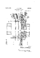
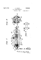
Fig. 1 is a plan View of the equipment used;
Fig. 2 is an end view looking in the direction of the arrows 2-2 of Fig. 1;
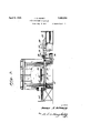
Fig. 3 is a detail longitudinal view of the gripping and quenching mechanism;
Fig. 4 is a cross section of the same mechanism taken on the line 4-4 of Fig. 3; and
Fig. 5 is a detail view of the quenching apparatus.
Now proceeding to a description of the mechanism and the method of its application: The sucker rod 10, having pin end 11, wrench square 12 and with the thickened portion 13 between the wrench square and the shank proper of the rod and collar 14 between the wrench square and the pin end 11, is rolled from the stock stand 15 into charging trough 16. This trough is mounted upon trolleys 16 adapted to ride upon trackways 17. The trough is moved into position opposite grooves 19 of heating furnace 18 and the rod pushed from the charging trough into the furnace. Here the rod is heated for a period of about forty-five minutes to give it a temperature of from say 1550 to 1600 F., substantially uniform from end to end of the rod. Drawing trough 20, mounted upon trolleys 20 and sliding upon trackways 17, is moved into position opposite the rod in furnace 18 and the rod drawn into the trough. The trough is then moved to table 21.
Here the rod is gripped at its ends in devices 22 and 23, device 22 is adapted to grip one end of sucker rod 10 and device 23 the other end. Device 22 is connected by means of chain 24 with cross head 25 mounted on piston 26' of air cylinder 26. Device 23 is connected by means of chain 27 and swivel 27 to cross head 28 to which is attached 1930. Serial No. 473,094.
cable 29 passing over pulley 30 and connected to yieldable restraining means such as weight 31.
Devices 22 and 23 are essentially the same in structure; therefore a description of one of them will suflice for both. Arms 32 have rod gripping fingers 33. These arms are provided at an intermediate region with lugs 34 which contain openings 35 whereby the arms may be pivotally mounted in opposing relationship on pin 36, which latter is mounted in the inwardly projecting lugs 37 of supporting body 38. Pivoted to the outer ends of arms 32 are links 39, which latter are pivotally connected to clevis 40. To clevis 40 of device 22 is attached one end of chain 24 and to clevis 40 of device 23 is attached an end of chain 27. By means of compression spring 41, placed between arms 32 and held in position by bosses 42, arms 32 normally tend to effect a gripping action on the rod by gripping fingers 33.
Supporting bodies 38, which support devices 22 and 23, are provided with circular flanges or tires 43 which rest upon smooth plates 44. Webs 45 of.bodies 38 are provided with circular holes through which ass nozzles 48 of the end quenching mechanlsm.
Each of the quenching devices comprises a manifold 46 which is connected with a source of compressed air by means of pipe 47. Connected with manifold 46 are nozzle pipes 48 which are adapted to pass through the holes in Web 45. Pipes 48 are provided with openings 49 disposed in proximity to the end regions of the sucker rod, whereby air may be streamed upon wrench squares 12 and pin ends 11 of the sucker rod.
Devices 22 and 23 are brought into position at the ends of rod and arms 32 pressed together against the action of spring 41 to open the gripping elements 33 and these are placedin position upon the wrench square 12 at each end of the rod, the pressure of spring 41 serving to effect a gripping engagement of fingers 33 upon the rod. Air is admitted to cylinder 26 and cross head 25 is carried suddenly to the right, as viewed in Figs. 1 and 3, jerking the rod in the same direction and elevating the weight 31. This der tension as justoutlined, serves to actuate the toggles containing links 39 to produce a very effective gripping of fingers 33 upon the ends of the rod.
The predetermined longitudinal motion of cross head 25 serves to operate contactor 51 which closes the circuit through solenoid 51' and thereby serves to open air valve 52 to admit air to manifold 46 and thus to produce a flow of air through openings 49 of nozzle pipes 48 to efiect a rapid cooling of the end regions of the sucker rods including pin ends 12, wrench squares 13 and collars 14. The air flow continues until timer mechanism 53 in the same circuit opens the circuit through the solenoid thereby causing valve 52 to close. The time of the quenching operationwill vary somewhat but should be sulficient to permit practically the entire mass of the end regions which are receiving the flow of air to cool below the critical range. Fol-v lowing the quenching operation the principal mass of the rod, at the end of the quench is still above the critical range and the residual heat in the rod serves to eflect a drawing of the quenched ends.
Tension is maintained on the rod until the entire mass thereof has passed through the critical range. When the rod has cooled below the critical range the gripping mechanism is released from the end of the rod which is allowed to cool to a somewhat lower temperature on table 21.
While still at an elevated tem erature, however, say at a temperature of rom 600 to 700 F. the rod is moved from table 21 onto dippin rack 54 whereby the rod is dipped into a bath of tar 55 and then raised therefrom while still at an elevated temperature to permit the tar to burn on. The rod is then discharged ontostand 56.
Having thus describedmy invention what "I claim and desire to secure by Letters Pat ent is:
1. In a mechanism for subjecting a rod to tension, a gripping member for each end of rod, yieldable restraining means attached to the gripping member at one end of the rod and means attached to the gripping member at the other end of the rod to exercise force on said rod in opposition to that exerted by said restraining means. 35 2. In a mechanism for subjecting a rod to tension, a gripping member for each end of the rod, a weight attachedto the gripping member at one end of the rod, and means operatively connected to the gripping member at the other end of the rod to suddenly apply force to the rod in a direction opposite to that exerted by said weight.
3. In a mechanism for subjecting a rod to tension, a gripping member for each end of the rod, yieldable restraining means attached to the gripping member at one end of the rod, and a swivel connection between the gripping member and the restraining means.
4. In a mechanism for subjecting a rod to tension, a gripping member forea h end of the rod, yieldable restraining means attached to the grlpping member at one end of the rod, a swivel connection between the gripping member and the restraining means, and a circular supporting member for the gripping mechanism adapted to bear upon the smooth surface.
5. In a mechanism for subjecting a rod to tension, a gripping member for each end of the rod, yieldable restraining means attached to the gripping member at one end of the rod, a. swivel connection between the gripping member and the restraining means, and a circular supporting member for each of the gripping members.
6. In a mechanism for subjecting a rod to tension, a gripping member for each end of the rod, a weight attached to the gripping member at one end of the rod, and means attached at the other end of the rod for sud denly moving the rod against action of the weight.
7. In a rod heat treatment mechanism, a gripping member for each end of the rod, a weight attached to the gripping member at one end of the rod, means attached at the other end of the rod for suddenly moving the rod against action of weight, and cooling means effective upon a predetermined longitudinal movement of an end of the rod for applying cooling fluid to the ends of the rod.
8. In a rod heat treatment mechanism, a gripping member for each end of a rod, a' weight attached to the gripping member at one end of the rod, and means attached to gripping member at the other end of the rod for suddenly moving rod against action of weight, and cooling means eflfectivef'npon movement of rod for applying cooling fluid iizio elds of rods, and means for timing flow of 9. In a mechanism for subjecting a rod to tension, a gripping member for each end of the rod, a weight attached to a gripping member at one end of the rod, and means flexibly connected to the gripping member at the other end of the rod for exerting force on the rod in a direction opposite to that exerted by lar supporting member for each of said grippin members adapted to bear upon a smooth sur ace.
10. In a mechanism for subjecting a rod to tension a gripping member for each end of the r0 a weight attached to a gripping member at one end of the rod, and means connected to gripping member at the other end of the rod for exerting a straightening force on the rod in a direction opposite to that exerted by said weight, a swivel connection between said weight and the gripping member, circular supporting members for both of said gripping members, adapted to bear upon a smooth surface, and means for normally tending to render the gripping means eflective upon application of such straightening force.
11. In a mechanism for subjecting a rod to tension, a gripping member for each end of the rod, means attached to the gripping member at one end of the rod adapted to exert a pull on the rod when the rod is moved lengthwise in one direction, and mechanism attached to the gripping member at the other end of the rod to move the rod to render said means effective, whereby the rod may be placed under longitudinal tension.
12. In a mechanism for subjecting a rod to tension, a gripping member for each end of the rod, a weight, adapted, normally to be independently supported, attached to the gripping member at one end of the rod and means normally attached to the gripping member at the other end of the rod for moving the rod longitudinally to suddenly lift the weight from its supported position and thereby to suddenly place the rod under longitudinal tension.
13. In a machine for subjecting a rod to tension, a gripping member for each end of the rod, means attached to each of the gripping members for effecting a pull on the rod in opposite directions, and a swivel between one of said gripping members and said means.
In testimony whereof I hereunto afiix my signature.
JAMES A. KINNEY.
Priority Applications (1)
| Application Number | Priority Date | Filing Date | Title |
|---|---|---|---|
| US473094A US1852528A (en) | 1930-08-04 | 1930-08-04 | Heat treatment mechanism |
Applications Claiming Priority (1)
| Application Number | Priority Date | Filing Date | Title |
|---|---|---|---|
| US473094A US1852528A (en) | 1930-08-04 | 1930-08-04 | Heat treatment mechanism |
Publications (1)
| Publication Number | Publication Date |
|---|---|
| US1852528A true US1852528A (en) | 1932-04-05 |
Family
ID=23878180
Family Applications (1)
| Application Number | Title | Priority Date | Filing Date |
|---|---|---|---|
| US473094A Expired - Lifetime US1852528A (en) | 1930-08-04 | 1930-08-04 | Heat treatment mechanism |
Country Status (1)
| Country | Link |
|---|---|
| US (1) | US1852528A (en) |
Cited By (3)
| Publication number | Priority date | Publication date | Assignee | Title |
|---|---|---|---|---|
| US2880739A (en) * | 1955-09-15 | 1959-04-07 | United States Steel Corp | Apparatus for quenching and reeling rods |
| US3138493A (en) * | 1962-03-19 | 1964-06-23 | Brush Beryllium Co | Method of heat treating beryllium copper alloys |
| US3202555A (en) * | 1964-09-28 | 1965-08-24 | Ohio Crankshaft Co | Apparatus and method of inductively hardening a shaft-like member |
-
1930
- 1930-08-04 US US473094A patent/US1852528A/en not_active Expired - Lifetime
Cited By (3)
| Publication number | Priority date | Publication date | Assignee | Title |
|---|---|---|---|---|
| US2880739A (en) * | 1955-09-15 | 1959-04-07 | United States Steel Corp | Apparatus for quenching and reeling rods |
| US3138493A (en) * | 1962-03-19 | 1964-06-23 | Brush Beryllium Co | Method of heat treating beryllium copper alloys |
| US3202555A (en) * | 1964-09-28 | 1965-08-24 | Ohio Crankshaft Co | Apparatus and method of inductively hardening a shaft-like member |
Similar Documents
| Publication | Publication Date | Title |
|---|---|---|
| US3506755A (en) | Molding apparatus and methods | |
| US2048937A (en) | Enameling machine | |
| DE2000271A1 (en) | Method and device for processing glass | |
| US1852528A (en) | Heat treatment mechanism | |
| US2280064A (en) | Inductive heating apparatus | |
| US2240493A (en) | Wheel hardening apparatus | |
| US4240616A (en) | Apparatus for heat-treating metallic material | |
| US2003094A (en) | Metal article and method of preparing same | |
| CN110508426A (en) | A kind of overhead type polyurethane continuous spray direct burial heat preservation production line | |
| US2328827A (en) | Apparatus for stretching thermostretchable elastoplastic film | |
| JPS5855220B2 (en) | Multi-purpose in-line direct heat treatment equipment for steel wire rods | |
| US3682721A (en) | Process for the improvement of the development of the texture of inductive surface-hardened steel parts | |
| US3072266A (en) | Material handling apparatus | |
| US1759603A (en) | Method of heat treatment | |
| US1836112A (en) | Method of truing rings | |
| US1260624A (en) | Apparatus for annealing and straightening pipe. | |
| US1914642A (en) | Method and apparatus for treating steel sheets | |
| US1712081A (en) | Apparatus for feeding articles | |
| GB266730A (en) | Improved process and apparatus for strengthening the heads of railway rails | |
| US1592661A (en) | Heat-treating machine | |
| US1773525A (en) | Means for drying cylindrical articles | |
| US1689048A (en) | Method of and apparatus for annealing glass | |
| US3410594A (en) | Workpiece loading fixture | |
| US1705084A (en) | Method of drying cylindrical articles | |
| SU396377A1 (en) | AUTOMATED INSTALLATION FOR ELECTROCONTACT HEATING AND COOLING OF PRODUCTS |