US1852524A - Suspended scaffold - Google Patents
Suspended scaffold Download PDFInfo
- Publication number
- US1852524A US1852524A US426063A US42606330A US1852524A US 1852524 A US1852524 A US 1852524A US 426063 A US426063 A US 426063A US 42606330 A US42606330 A US 42606330A US 1852524 A US1852524 A US 1852524A
- Authority
- US
- United States
- Prior art keywords
- drum
- cross
- shaft
- cable
- frame
- Prior art date
- Legal status (The legal status is an assumption and is not a legal conclusion. Google has not performed a legal analysis and makes no representation as to the accuracy of the status listed.)
- Expired - Lifetime
Links
Images

Classifications
-
- E—FIXED CONSTRUCTIONS
- E04—BUILDING
- E04G—SCAFFOLDING; FORMS; SHUTTERING; BUILDING IMPLEMENTS OR AIDS, OR THEIR USE; HANDLING BUILDING MATERIALS ON THE SITE; REPAIRING, BREAKING-UP OR OTHER WORK ON EXISTING BUILDINGS
- E04G3/00—Scaffolds essentially supported by building constructions, e.g. adjustable in height
- E04G3/28—Mobile scaffolds; Scaffolds with mobile platforms
- E04G3/30—Mobile scaffolds; Scaffolds with mobile platforms suspended by flexible supporting elements, e.g. cables
- E04G3/32—Hoisting devices; Safety devices
Definitions
- My invention relates to suspended scaffolds for use by brioklayers, interior decorators, plasterers and the like, and it involves features making it a distinct improvement to overcome certain practical objections to, and defects in, the present types of suspended scafiolds.
- the hoisting mechanism is, as a whole,
- the primary object of my invention resides in providing a suspended scaffold wherein the cable drums of the hoisting mechanism are disposed entirely below the upper plane of the workinens platform.
- a further object of the invention resides in a cable operating unit, wherein shaft supported pinion gears that are adapted to mesh with gears forming the end walls of the cable drum for rotating the drums when winding the cable thereon, can be shifted out of mesh with the drum gears leaving the drum free for rotation in either direction.
- a still further object of the invention is the provision of a suspended scaffold which possesses advantages in points of simplicity and eficiency, and, at the same time proves itself comparatively inexpensive in cost of manufacture.
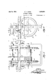
- Fig. 1. is an end elevation of a suspended scaffold supported in place at the side of a building under construction.
- Fig. 2 is a side elevation of one of the windlass hoisting units, partly broken away.
- Fig. 3 is an end elevation of one of the hoisting units. 1
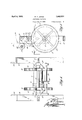
- Fig. 4 is a top plan view of one of the hoisting units.
- Fig. 5 is a sectional elevation of the hoisting unit.
- a building column is designated 1 and a cross-beam arranged horizontally is designated 2.
- An outrigger, or beam 3 is secured to the crossbeam by means of one or more suitable clamping devices 4 and extends out beyond the column 1.
- a pair of suitable clamping devices 5 are carried in spaced relation by each outrigger 3 and to each clamping device 5, the upper end of a suitable hoisting cable 6 is secured.
- Each cable 6 is Wound about a drum embodying a cylindrical core 7 and the end walls 8 and the lower end of each cable is secured to one of the end walls of the drums by means of a clamping device 9.
- Each drum is fixed to a shaft 10, the ends of which are journaled in the arms 11 of a U-shaped Windlass frame 12.
- Windlass frames are united in fixed spaced relation by means of a pair of spaced angle iron cross-beams 13 which engage the outer faces of the arms 11 of the frames 12 and secured to the frames by means of bolts 14: carrying nuts 15 so that the cross-beams can be detached from the Windlass frames when desired, such as when taking down the scaffold and moving it from one job to another.
- Each Windlass frame is provided with a cross-shaft 16 which is journaled at its ends in the arms 11 of the frame and disposed above the cable drum in parallel relation and in vertical alignment with the drum shaft 10.
- a pair of pinion gears 17 are adapted to mesh with gear teeth 18 formed on the peripheral face of the end walls 8 of the drum.
- the ends of the shaft 16 are square in crosssection and eitherend is adapted to receive IOU naled in they arms 11 of the indlass frame and is provided with a pair of fixed pawlsor dogs 22, the free ends of which are directed downwardly and adapted for engagement iwiththe gear teeth 18 of the end walls 8 of the cable drum to prevent accidental unwinding of the cable from the drum.
- a pair of spacer blocks 23 are pivot-ally supported upon the cross-shaft 21 between the pawls 22 and the arms 11 of the Windlass frame and are normally adapted to assume a depending position so that the free ends thereof will lie between the pinion gears of shaft'16 and the arms 11 of the Windlass frame to prevent longitudinal sliding movement of the pinion gear shaft 16.
- the free ends of the spacer blocks are recessed, as at 24, to fit the contour of the pinion gear shaft.
- the pinion gear shafts 16 can be moved longitudinally to disengage the pinion gears 17 from mesh with the drum gear teeth 18 so that the drum can be rotated for winding or unwinding the cable thereon without having to rotate the pinion gear shaft 16.
- the cross-shaft 21 carrying the fixed pawls 22 is rotated for elevating the paWls 22 by means of. a suitable lever handle 25 which is detachably connected to either end of the cross-shaft 21.
- each cross-beam 13 is directed upwardly a short distance, as at 29 and 30 to provide posts to. which uprights 31 and 32 can be suitably connected.
- the uprights 31 and 32 are connected at their upper ends by means of a cross-member 33 upon which boards 3& are laid to provide a cover for the scaffold.
- the upright 32 is offset, as at 35, so as to prevent the uprights above the offset portion thereof and the cover from striking the column 1 should the upper end of the scaffold be tilted toward the building.
- the spaced cross-beams 13 connecting a pair ofspaced Windlass frames 12 are adapted to support suitable planking 36 to act as a platform for the support of workmen, ma-
- each Windlass frame is disposed below the upper plane of platform planking, thereby leaving but a short section of the upper ends ofthewindlass frames extending above the platform planking and of such a height that workmen can readily step over the upper extendedends of the frames, if necessary, and, thereby not illterfering with the'work of the men upon the platform, as is the case when the entire windlass frame is disposed abovethe upper plane of the platform.
- the uprights 32 being offset enable the workmen to readily lay brick, or perform other duties between the uprightand the building Wall, whether skeleton, or solid. 7 i Y
- the many advantages of the herein described invention will readily suggest themselves to those skilled in the art to which it appertains.
- VVhatIclaim is: 1. In a scaffold support, the combination of a pair of spaced U-shaped' frames'of like structure, a pair of spaced cross-beams unit ing said frames, a cable carrying drum ro-. tatably mounted between the arms ofeach frame, gear teeth formed on the periphery of the end walls of each drum, a longitudinally slidable cross shaft disposed above the drum of each frame and: journaled in the arms of each frame, pinion gearsfixed on each shaft and adapted to mesh with the gear teeth of the drum walls for rotating: the
- a hoisting device for suspended scaffolds comprising a U-shaped frame, a cable carrying drum mounted for rotation between the arms of the frame, gear teeth formed on the periphery of the end walls of the drum, a longitudinally slidable cross shaft journaled in the arms of the frame above the drum, pinion gears fixed to said cross shaft adapted to mesh with the gear teeth of the end walls of the drum, a second cross shaft journaled in the arms of the frame above the longitudinally slidable cross shaft, dogs fixed to the second cross shaft and adapted to engage the gear teeth on the end Walls of the drum to prevent unwinding of the cable from the drum, depending means pivoted to the second cross shaft, which when raised, permits longitudinal movement of the slidable cross shaft for disengaging the pinion gears carried thereby from the gear teeth of the drum, a third cross shaft, means for supporting said cross shaft adjacent the second cross shaft and a peripherally grooved cable engaging idler mounted upon said third cross shaft for both rotary and longitudinal sliding movement thereon.
- a pair of spaced cross-bars having upwardly directed ends, planking laid upon said crossbars, a hoisting frame disposed between said bars near the ends thereof, means for removably securing said frames to said bars, each frame comprising upright members of equal length and connected at their lower ends by means of a cross-bar, a drum mounted between said upright frame members about which a cable is adapted to be wound, gear teeth formed on the periphery of the end walls of the drum, a rotatable and longitudinally slidahle cross shaft supported by said upright frame members, pinion gears fixed on said cross shaft and adapted to mesh with the gear teeth of the drum for rotating the drum in either direction, pawls associated with the gear teeth of the drum to prevent unwinding of the cable wound upon the drum, means for lifting the pawls in unison from engagement with the gear teeth of the drum, means to permit shifting of the pinion gears from engagement with the gear teeth of the drum, a cross-shaft supported by said
Landscapes
- Engineering & Computer Science (AREA)
- Architecture (AREA)
- Mechanical Engineering (AREA)
- Civil Engineering (AREA)
- Structural Engineering (AREA)
- Movable Scaffolding (AREA)
Description
April 5, 1932. w. F. JONES SUSPENDED SGAFFOLD Filed Feb. 5, 1930 5 Sheejcs-Sheetl ,3 INVENTOR:
iffil/wwa.
TORNEY April 5, 1932. w. F.-J ONES SUSPENDED SCAFFOLD Filed Feb. 5. 1930 3 Sheets-Sheet 2 I I l l llllilllll INVENTOR. BY Wit/07255. %'za 0 NEY April 5, 1932. JONES 1,852,524
SUSPENDED SCAFFOLD Filed Feb. 5. 1930 3 Sheets-Sheet 3 1r" INVENTOR.
Patented Apr. 5, 1932 PATENT OFFICE WILLIAM F. JONES, OF ST. LOUIS, MISSOURI SUSPENDED SCAFFOLD Application filed February 5, 1930. Serial No. 426,063.
My invention relates to suspended scaffolds for use by brioklayers, interior decorators, plasterers and the like, and it involves features making it a distinct improvement to overcome certain practical objections to, and defects in, the present types of suspended scafiolds.
In the present types of suspended scaffolds, the hoisting mechanism is, as a whole,
disposed above the workmens platform and it is constantly in the way of the workmen, making it hard for bricklayers to lay brick behind the hoisting unit closest to the wall being laid. a
The primary object of my invention resides in providing a suspended scaffold wherein the cable drums of the hoisting mechanism are disposed entirely below the upper plane of the workinens platform.
A further object of the invention resides in a cable operating unit, wherein shaft supported pinion gears that are adapted to mesh with gears forming the end walls of the cable drum for rotating the drums when winding the cable thereon, can be shifted out of mesh with the drum gears leaving the drum free for rotation in either direction.
A still further object of the invention is the provision of a suspended scaffold which possesses advantages in points of simplicity and eficiency, and, at the same time proves itself comparatively inexpensive in cost of manufacture.
lVith the above and other objects in view, the invention consists of the novel features of construction, arrangement and combination of parts hereinafter more fully described and finally pointed out in the claims hereto appended.
Referring to the accompanying drawings forming a part of this specification, wherein like characters of reference denote similar parts throughout the several views:
Fig. 1. is an end elevation of a suspended scaffold supported in place at the side of a building under construction.
Fig. 2 is a side elevation of one of the windlass hoisting units, partly broken away.
Fig. 3 is an end elevation of one of the hoisting units. 1
iii.)
Fig. 4 is a top plan view of one of the hoisting units.
Fig. 5 is a sectional elevation of the hoisting unit.
Referring to the drawings, a building column is designated 1 and a cross-beam arranged horizontally is designated 2. An outrigger, or beam 3, is secured to the crossbeam by means of one or more suitable clamping devices 4 and extends out beyond the column 1. There may be as many outriggers used as desired, which are spaced a suitable distance apart.
A pair of suitable clamping devices 5 are carried in spaced relation by each outrigger 3 and to each clamping device 5, the upper end of a suitable hoisting cable 6 is secured. Each cable 6 is Wound about a drum embodying a cylindrical core 7 and the end walls 8 and the lower end of each cable is secured to one of the end walls of the drums by means of a clamping device 9. Each drum is fixed to a shaft 10, the ends of which are journaled in the arms 11 of a U-shaped Windlass frame 12.
Two Windlass frames are united in fixed spaced relation by means of a pair of spaced angle iron cross-beams 13 which engage the outer faces of the arms 11 of the frames 12 and secured to the frames by means of bolts 14: carrying nuts 15 so that the cross-beams can be detached from the Windlass frames when desired, such as when taking down the scaffold and moving it from one job to another.
Two frames, each carrying a cable drum and the two cross-beams secured thereto to hold the frames in their proper spaced relation constitute what I term a hoistable platform supporting unit.
Each Windlass frame is provided with a cross-shaft 16 which is journaled at its ends in the arms 11 of the frame and disposed above the cable drum in parallel relation and in vertical alignment with the drum shaft 10. A pair of pinion gears 17 are adapted to mesh with gear teeth 18 formed on the peripheral face of the end walls 8 of the drum. The ends of the shaft 16 are square in crosssection and eitherend is adapted to receive IOU naled in they arms 11 of the indlass frame and is provided with a pair of fixed pawlsor dogs 22, the free ends of which are directed downwardly and adapted for engagement iwiththe gear teeth 18 of the end walls 8 of the cable drum to prevent accidental unwinding of the cable from the drum.
A pair of spacer blocks 23 are pivot-ally supported upon the cross-shaft 21 between the pawls 22 and the arms 11 of the Windlass frame and are normally adapted to assume a depending position so that the free ends thereof will lie between the pinion gears of shaft'16 and the arms 11 of the Windlass frame to prevent longitudinal sliding movement of the pinion gear shaft 16. The free ends of the spacer blocks are recessed, as at 24, to fit the contour of the pinion gear shaft.
Vhenever the spacer blocks 23 are moved into an elevated position and the pawls 22 raised out of contact with the gear teeth 18 of the drum ends, the pinion gear shafts 16 can be moved longitudinally to disengage the pinion gears 17 from mesh with the drum gear teeth 18 so that the drum can be rotated for winding or unwinding the cable thereon without having to rotate the pinion gear shaft 16. The cross-shaft 21 carrying the fixed pawls 22 is rotated for elevating the paWls 22 by means of. a suitable lever handle 25 which is detachably connected to either end of the cross-shaft 21.
Disposed in parallel relation to the crosss'haft 21 and spaced directly opposite therefrom, isa fixed cross-shaft 26 carried by lateral extensions 27 at the upper ends of the arms 11 of the Windlass frame. A. rotatably 4 and slidably mounted peripherally grooved roller 28 is carried by the shaft 26 and is adapted to act as a guide roller for the cable 6,-as it is wound upon and unwound from the cable drum. j v 1 Opposite ends of each cross-beam 13 is directed upwardly a short distance, as at 29 and 30 to provide posts to. which uprights 31 and 32 can be suitably connected. The uprights 31 and 32 are connected at their upper ends by means of a cross-member 33 upon which boards 3& are laid to provide a cover for the scaffold. The upright 32 is offset, as at 35, so as to prevent the uprights above the offset portion thereof and the cover from striking the column 1 should the upper end of the scaffold be tilted toward the building.
The spaced cross-beams 13 connecting a pair ofspaced Windlass frames 12 are adapted to support suitable planking 36 to act as a platform for the support of workmen, ma-
wherein the cable drum of each Windlass frame is disposed below the upper plane of platform planking, thereby leaving but a short section of the upper ends ofthewindlass frames extending above the platform planking and of such a height that workmen can readily step over the upper extendedends of the frames, if necessary, and, thereby not illterfering with the'work of the men upon the platform, as is the case when the entire windlass frame is disposed abovethe upper plane of the platform. Also, the uprights 32 being offset enable the workmen to readily lay brick, or perform other duties between the uprightand the building Wall, whether skeleton, or solid. 7 i Y The many advantages of the herein described invention will readily suggest themselves to those skilled in the art to which it appertains. v
From the foregoing description, it is evi-. dent that a simple device for this purpose has been disclosed, but it is to be understood that I do not desire to restrict, or limit myself to the very details of the construction shown and described, which is merely illustrative, it being obvious that changes, not involving the exercise of invention, may be made without conflicting or departing from the spirit of the invention within the scope of the ap-V pended claims. 1
VVhatIclaim is: 1. In a scaffold support, the combination of a pair of spaced U-shaped' frames'of like structure, a pair of spaced cross-beams unit ing said frames, a cable carrying drum ro-. tatably mounted between the arms ofeach frame, gear teeth formed on the periphery of the end walls of each drum, a longitudinally slidable cross shaft disposed above the drum of each frame and: journaled in the arms of each frame, pinion gearsfixed on each shaft and adapted to mesh with the gear teeth of the drum walls for rotating: the
drums upon rotation of the cross shafts, a second cross shaft journaled' in the arms of the U-shaped frames, dogs fixed to the latter shaft of each frame adapted for engagement with the gear teeth of the walls of the drums to prevent unwindingof the cables from the drums, means for releasing the dogs from engagement with the gear teeth of the drum walls to permit unwinding of the cables from the drums, means permitting longitudinal movement of the pinion gear shaft of each frame for disengaging the pinion gears from the gear teeth of the drum walls to permit rotation of the drums in either direction and a hoisting cable carried by each drum, the upper ends of which are adapted to be secured to an over head support.
2. A hoisting device for suspended scaffolds comprising a U-shaped frame, a cable carrying drum mounted for rotation between the arms of the frame, gear teeth formed on the periphery of the end walls of the drum, a longitudinally slidable cross shaft journaled in the arms of the frame above the drum, pinion gears fixed to said cross shaft adapted to mesh with the gear teeth of the end walls of the drum, a second cross shaft journaled in the arms of the frame above the longitudinally slidable cross shaft, dogs fixed to the second cross shaft and adapted to engage the gear teeth on the end Walls of the drum to prevent unwinding of the cable from the drum, depending means pivoted to the second cross shaft, which when raised, permits longitudinal movement of the slidable cross shaft for disengaging the pinion gears carried thereby from the gear teeth of the drum, a third cross shaft, means for supporting said cross shaft adjacent the second cross shaft and a peripherally grooved cable engaging idler mounted upon said third cross shaft for both rotary and longitudinal sliding movement thereon.
3. In a platform supporting structure, a pair of spaced cross-bars having upwardly directed ends, planking laid upon said crossbars, a hoisting frame disposed between said bars near the ends thereof, means for removably securing said frames to said bars, each frame comprising upright members of equal length and connected at their lower ends by means of a cross-bar, a drum mounted between said upright frame members about which a cable is adapted to be wound, gear teeth formed on the periphery of the end walls of the drum, a rotatable and longitudinally slidahle cross shaft supported by said upright frame members, pinion gears fixed on said cross shaft and adapted to mesh with the gear teeth of the drum for rotating the drum in either direction, pawls associated with the gear teeth of the drum to prevent unwinding of the cable wound upon the drum, means for lifting the pawls in unison from engagement with the gear teeth of the drum, means to permit shifting of the pinion gears from engagement with the gear teeth of the drum, a cross-shaft supported by said upright frame members, a rotatable and slidably mounted cable guide roller mounted on said cross-shaft for guiding the cable directed upwardly from the drum, said drum being disposed completely below the planks of the platform, corner uprights connected to the upright ends of one of the crossbars, one of said uprights being offset in its length, a cross bar connecting the upper ends of the uprights and a board covering supported by said last named cross-bar.
In testimony whereof, I have hereunto afiixed my signature.
WILLIAM F. JONES.
Priority Applications (1)
| Application Number | Priority Date | Filing Date | Title |
|---|---|---|---|
| US426063A US1852524A (en) | 1930-02-05 | 1930-02-05 | Suspended scaffold |
Applications Claiming Priority (1)
| Application Number | Priority Date | Filing Date | Title |
|---|---|---|---|
| US426063A US1852524A (en) | 1930-02-05 | 1930-02-05 | Suspended scaffold |
Publications (1)
| Publication Number | Publication Date |
|---|---|
| US1852524A true US1852524A (en) | 1932-04-05 |
Family
ID=23689129
Family Applications (1)
| Application Number | Title | Priority Date | Filing Date |
|---|---|---|---|
| US426063A Expired - Lifetime US1852524A (en) | 1930-02-05 | 1930-02-05 | Suspended scaffold |
Country Status (1)
| Country | Link |
|---|---|
| US (1) | US1852524A (en) |
Cited By (1)
| Publication number | Priority date | Publication date | Assignee | Title |
|---|---|---|---|---|
| US4508482A (en) * | 1983-02-25 | 1985-04-02 | University Of Kentucky Research Foundation | Method and apparatus for harvesting tobacco |
-
1930
- 1930-02-05 US US426063A patent/US1852524A/en not_active Expired - Lifetime
Cited By (1)
| Publication number | Priority date | Publication date | Assignee | Title |
|---|---|---|---|---|
| US4508482A (en) * | 1983-02-25 | 1985-04-02 | University Of Kentucky Research Foundation | Method and apparatus for harvesting tobacco |
Similar Documents
| Publication | Publication Date | Title |
|---|---|---|
| US4102463A (en) | Transporter for slab casting tables | |
| US4444289A (en) | Construction platform and method | |
| US3323616A (en) | Mason's scaffold | |
| US2623643A (en) | Scaffold raiser and remover | |
| US2531346A (en) | Builder's hoist | |
| US3817347A (en) | U-frame scaffolding assembly | |
| US3379281A (en) | Method and equipment for building construction | |
| US3464520A (en) | Self-operated elevator | |
| US3223199A (en) | Scaffolding hoist | |
| US2857026A (en) | Device for erecting elevator towers | |
| US2178956A (en) | Shiftable scaffold apparatus | |
| US2890082A (en) | Hoisting attachment for tubular steel scaffolds | |
| US1852524A (en) | Suspended scaffold | |
| US3394776A (en) | Suspended traveling scaffold | |
| US3468514A (en) | Lifting assembly for lift-slab-type building construction | |
| US2553031A (en) | Scaffold winch | |
| US1175049A (en) | Material-elevator. | |
| JP2011252318A (en) | Load receiving platform and its transferring method | |
| US2578631A (en) | Erection of buildings | |
| DE494148C (en) | Work scaffolding for building walls | |
| JPS6015774Y2 (en) | Mobile concrete formwork equipment for embankments | |
| US3333712A (en) | Mobile platform and hoisting apparatus | |
| US3083787A (en) | Scaffold structure | |
| US2928642A (en) | Scaffold bracket | |
| DE588906C (en) | crane |