US1852521A - Tool - Google Patents
Tool Download PDFInfo
- Publication number
- US1852521A US1852521A US533035A US53303531A US1852521A US 1852521 A US1852521 A US 1852521A US 533035 A US533035 A US 533035A US 53303531 A US53303531 A US 53303531A US 1852521 A US1852521 A US 1852521A
- Authority
- US
- United States
- Prior art keywords
- clamps
- clamp
- sleeve
- tool
- engaging
- Prior art date
- Legal status (The legal status is an assumption and is not a legal conclusion. Google has not performed a legal analysis and makes no representation as to the accuracy of the status listed.)
- Expired - Lifetime
Links
- 230000000295 complement effect Effects 0.000 description 7
- 238000006073 displacement reaction Methods 0.000 description 3
- 230000008439 repair process Effects 0.000 description 2
- 238000010276 construction Methods 0.000 description 1
- 239000002184 metal Substances 0.000 description 1
Images
Classifications
-
- B—PERFORMING OPERATIONS; TRANSPORTING
- B21—MECHANICAL METAL-WORKING WITHOUT ESSENTIALLY REMOVING MATERIAL; PUNCHING METAL
- B21K—MAKING FORGED OR PRESSED METAL PRODUCTS, e.g. HORSE-SHOES, RIVETS, BOLTS OR WHEELS
- B21K25/00—Uniting components to form integral members, e.g. turbine wheels and shafts, caulks with inserts, with or without shaping of the components
-
- Y—GENERAL TAGGING OF NEW TECHNOLOGICAL DEVELOPMENTS; GENERAL TAGGING OF CROSS-SECTIONAL TECHNOLOGIES SPANNING OVER SEVERAL SECTIONS OF THE IPC; TECHNICAL SUBJECTS COVERED BY FORMER USPC CROSS-REFERENCE ART COLLECTIONS [XRACs] AND DIGESTS
- Y10—TECHNICAL SUBJECTS COVERED BY FORMER USPC
- Y10T—TECHNICAL SUBJECTS COVERED BY FORMER US CLASSIFICATION
- Y10T29/00—Metal working
- Y10T29/53—Means to assemble or disassemble
- Y10T29/53796—Puller or pusher means, contained force multiplying operator
- Y10T29/53848—Puller or pusher means, contained force multiplying operator having screw operator
Definitions
- This invention relates to a tool primarily adapted to remove and replace an ignition cable now in use 011 certain automobiles, in making repairs.
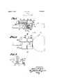
- Fig. l is a longitudinal sectional elevation of the tool showing it applied to a special type of ignition cable lock, and ready to separate the parts thereof;
- Fig. 2 is a corresponding inverted plan view
- Fig. 3 is a sectional elevation taken on the line III-III of Fig. 2.
- 10 is an ignition cable which terminates in a sleeve 11, the end of which is disposed in a recessed cylindrical block 12. 13 is a portion of the distributor box to which the cable is secured. From this box a rigidly held pin 1 1 having a bayonet shaped head 15 projects centrally through the block 12. Disposed within the sleeve 11 is a thin metal washer 16, having a star shaped central hole which is held agai nst removal by an annular externally threaded retaining ring 17, the hole in this-ring being larger than the bayonet head 15. 18 is an insulating ring and 19, a spring holding the washer against these rings.
- the tool comprises a pair of substantially U-shaped clamps 20, 21 arcuately chambered out to fit over the sleeve 11, and block 12. respectively.
- the engaging surface of clamp 20 is provided with V-shaped threads 22, to engage and bite into the cylindrical surface of the sleeve 11 and thereby secure a grip for 1931.
- the clamp 21 is provided with flanges 24, 25 to engage the ends of the block 12.
- Each of the clamps is provided with a set screw 26, 27 respectively, through which engagement of the clamps with the sleeve and block respectively, is completed.
- parallel guides 28 preferably smooth round rods, which pass through and have a sliding lit in complementary holes in the clamp 20.
- clamps 20 and 21 are brought close together.
- Clamp 21 is engaged over block 12, and clamp 20 over sleeve 11, and each is engaged to its respective part by the set screws 27, 26, the latter screw especially being set up tight enough to cause the threads 22 to bite into and engage -the sleeve.
- Screw 29 is then turned by a suitable wrench to separate the clamps and forcibly withdraw the sleeve 11 from the block 12, in so doing distorting and destroying the washer 16. After such disconnection the clamps are disengaged from the sleeve and block.
- the threaded ring 17 becomes accessible and may be removed to permit repair of the cable end, or a new cable and sleeve may be put in. In either event, the cable and attached sleeve 11 may be replaced by re-engagement of the clamps with the sleeve and block and turning the screw 29 to draw the parts together.
- a tool comprising a pair of U shaped clamps having arcuate engaging surfaces
- a tool comprising a pair of clamps having arcuate engaging surfaces, part-engaging-flanges at opposite ends of one of said clamps, corrugations in the engaging surface of the opposed clamp and means for securing in said clamps parts to be separated or engaged; one of said clamps having parallel guides extending from one end thereof and the other of said clamps having complementary holes through which said guides are slidably disposed, anda screw disposed par allel to said guides, rotatably secured against longitudinal displacement in one of said clamps and engaging complementary threads in the other of said clamps whereby said clamps may be forcibly separated or approached.
- a tool comprising a pair of U shaped clamps having arcuate engaging surfaces, U shaped part-engaging-flanges at opposite ends of one of said clamps, corrugations in the engaging surface of the opposed clamp and set screws passing each through a leg of a clamp forsecuring in said clamps, parts to be separated or engaged; one of said clamps having parallel guides extending from one end thereof and the other of said clamps having complementary holes through which said guides are slidably disposed, and a screw disposed parallel to said guides, rotatably secured against longitudinal displacement in one of said clamps and engaging complementary threads in the other of said clamps whereby said clamps may be forcibly separated or approached.
- a tool comprising a pair of U shaped clamps having arcuate engaging surfaces, U shaped part-engaging-flanges at opposite ends of one of said clamps, corrugations in the engaging surface of the opposed clamp and set screws each passing through a leg of a clamp for securing in said clamps parts to be separated or engaged, one of said clamps having parallel guides extending from one end thereof and the other of said clamps having complementary holes through which said guides are slidably disposed, and means for forcibly advancing or retracting one of said clamps toward or away from the other thereof and along said guides.
Landscapes
- Engineering & Computer Science (AREA)
- Mechanical Engineering (AREA)
- Supports For Pipes And Cables (AREA)
Description
April 5, 1932. H. E. HILL 1,852,521
TOOL
Filed April 27, 19:51
Patented Apr. 5, 1932 UNITED STATES HUBER! E. HILL, OF MEMPHIS, TENNESSEE TOOL Application filed April 27,
This invention relates to a tool primarily adapted to remove and replace an ignition cable now in use 011 certain automobiles, in making repairs.
The objects of the invention are:
To provide means for securely engaging the two parts which are to be separated, each to a clamp, and for forcibly separatnig these clamps to disengage the parts, and reversely for forcibly approaching the two clamps to engage parts carried thereby together; and
To simplify the design and construction of such a tool.
The means by which the foregoing and other objects are accomplished and the man-- nor of their accomplishment will readily be understood from the following specification on reference to the accompanying drawings, in which:
Fig. l is a longitudinal sectional elevation of the tool showing it applied to a special type of ignition cable lock, and ready to separate the parts thereof;
Fig. 2 is a corresponding inverted plan view; and
Fig. 3 is a sectional elevation taken on the line III-III of Fig. 2.
Referring now to the drawings in which the parts are referred to by numerals, 10 is an ignition cable which terminates in a sleeve 11, the end of which is disposed in a recessed cylindrical block 12. 13 is a portion of the distributor box to which the cable is secured. From this box a rigidly held pin 1 1 having a bayonet shaped head 15 projects centrally through the block 12. Disposed within the sleeve 11 is a thin metal washer 16, having a star shaped central hole which is held agai nst removal by an annular externally threaded retaining ring 17, the hole in this-ring being larger than the bayonet head 15. 18 is an insulating ring and 19, a spring holding the washer against these rings.
The tool comprises a pair of substantially U-shaped clamps 20, 21 arcuately chambered out to fit over the sleeve 11, and block 12. respectively. The engaging surface of clamp 20 is provided with V-shaped threads 22, to engage and bite into the cylindrical surface of the sleeve 11 and thereby secure a grip for 1931. Serial No. 533,035.
removing the sleeve and with a shoulder 23 to engage the end of the sleeve in replacing it.
The clamp 21 is provided with flanges 24, 25 to engage the ends of the block 12. Each of the clamps is provided with a set screw 26, 27 respectively, through which engagement of the clamps with the sleeve and block respectively, is completed.
Secured in and projecting from the clamp 21 are parallel guides 28, preferably smooth round rods, which pass through and have a sliding lit in complementary holes in the clamp 20.
29 is a screw, disposed parallel to these guides. which threadedly engages the clamp 85 20, and is rotatably mounted in the clamp 21. Longitudinal movement of the screw relative to clamp 21 is prevented by the collar 30 and nut 31.
In using the tool the clamps 20 and 21 are brought close together. Clamp 21 is engaged over block 12, and clamp 20 over sleeve 11, and each is engaged to its respective part by the set screws 27, 26, the latter screw especially being set up tight enough to cause the threads 22 to bite into and engage -the sleeve.
After removal the threaded ring 17 becomes accessible and may be removed to permit repair of the cable end, or a new cable and sleeve may be put in. In either event, the cable and attached sleeve 11 may be replaced by re-engagement of the clamps with the sleeve and block and turning the screw 29 to draw the parts together.
Having described my invention, what I claim is:
1. A tool, comprising a pair of U shaped clamps having arcuate engaging surfaces,
U shaped partengaging-flanges at opposite ends of one of said clamps, corrugations in the engaging surface of the opposed clamp and set screws passing each through a leg of a clamp for securing in said clamps parts to be separated or engaged, and a screw rotatably secured against longitudinal displacement in one of said clamps and engaging complementary threads in the other of said clamps whereby said clamps may be forcibly separated or approached.
2. A tool, comprising a pair of clamps having arcuate engaging surfaces, part-engaging-flanges at opposite ends of one of said clamps, corrugations in the engaging surface of the opposed clamp and means for securing in said clamps parts to be separated or engaged; one of said clamps having parallel guides extending from one end thereof and the other of said clamps having complementary holes through which said guides are slidably disposed, anda screw disposed par allel to said guides, rotatably secured against longitudinal displacement in one of said clamps and engaging complementary threads in the other of said clamps whereby said clamps may be forcibly separated or approached.
3. A tool, comprising a pair of U shaped clamps having arcuate engaging surfaces, U shaped part-engaging-flanges at opposite ends of one of said clamps, corrugations in the engaging surface of the opposed clamp and set screws passing each through a leg of a clamp forsecuring in said clamps, parts to be separated or engaged; one of said clamps having parallel guides extending from one end thereof and the other of said clamps having complementary holes through which said guides are slidably disposed, and a screw disposed parallel to said guides, rotatably secured against longitudinal displacement in one of said clamps and engaging complementary threads in the other of said clamps whereby said clamps may be forcibly separated or approached.
4. A tool, comprising a pair of U shaped clamps having arcuate engaging surfaces, U shaped part-engaging-flanges at opposite ends of one of said clamps, corrugations in the engaging surface of the opposed clamp and set screws each passing through a leg of a clamp for securing in said clamps parts to be separated or engaged, one of said clamps having parallel guides extending from one end thereof and the other of said clamps having complementary holes through which said guides are slidably disposed, and means for forcibly advancing or retracting one of said clamps toward or away from the other thereof and along said guides.
In testimony whereof I hereunto affix my signature.
HUBERT E; HILL.
Priority Applications (1)
| Application Number | Priority Date | Filing Date | Title |
|---|---|---|---|
| US533035A US1852521A (en) | 1931-04-27 | 1931-04-27 | Tool |
Applications Claiming Priority (1)
| Application Number | Priority Date | Filing Date | Title |
|---|---|---|---|
| US533035A US1852521A (en) | 1931-04-27 | 1931-04-27 | Tool |
Publications (1)
| Publication Number | Publication Date |
|---|---|
| US1852521A true US1852521A (en) | 1932-04-05 |
Family
ID=24124188
Family Applications (1)
| Application Number | Title | Priority Date | Filing Date |
|---|---|---|---|
| US533035A Expired - Lifetime US1852521A (en) | 1931-04-27 | 1931-04-27 | Tool |
Country Status (1)
| Country | Link |
|---|---|
| US (1) | US1852521A (en) |
Cited By (3)
| Publication number | Priority date | Publication date | Assignee | Title |
|---|---|---|---|---|
| US4540199A (en) * | 1982-09-01 | 1985-09-10 | Neill David C | Jack bolt assembly |
| US4671324A (en) * | 1982-09-01 | 1987-06-09 | Neill David C | Jack bolt assembly |
| US8602390B2 (en) | 2010-11-30 | 2013-12-10 | General Electric Company | Jacking mechanism |
-
1931
- 1931-04-27 US US533035A patent/US1852521A/en not_active Expired - Lifetime
Cited By (3)
| Publication number | Priority date | Publication date | Assignee | Title |
|---|---|---|---|---|
| US4540199A (en) * | 1982-09-01 | 1985-09-10 | Neill David C | Jack bolt assembly |
| US4671324A (en) * | 1982-09-01 | 1987-06-09 | Neill David C | Jack bolt assembly |
| US8602390B2 (en) | 2010-11-30 | 2013-12-10 | General Electric Company | Jacking mechanism |
Similar Documents
| Publication | Publication Date | Title |
|---|---|---|
| US2323039A (en) | Welding apparatus | |
| US1465124A (en) | Bushing remover and replacer | |
| US2315792A (en) | Adapter | |
| US1815500A (en) | Stud extractor | |
| US1852521A (en) | Tool | |
| US1435278A (en) | Bearing puller | |
| US1631872A (en) | Gear puller | |
| US2168126A (en) | Pipe vise | |
| US2350404A (en) | Flange spreader | |
| US1406824A (en) | Flange wrench | |
| US3021112A (en) | Wedging tool | |
| US2341970A (en) | Cable clamp | |
| US1344544A (en) | Lock-nut | |
| US2951406A (en) | Broken nipple extractor | |
| US1343661A (en) | Gear-puller | |
| US2086587A (en) | Tool for removing and applying spark plugs | |
| US2422039A (en) | Clamping means | |
| US466255A (en) | Nipple holding chuck | |
| US1684226A (en) | Wheel puller | |
| US1442500A (en) | Bolt | |
| US1310270A (en) | Bushing-puller | |
| US1879334A (en) | Perch bolt remover | |
| US1422390A (en) | Bushing inserter or remover | |
| US2417598A (en) | Wrench for shielded spark plugs | |
| US1573646A (en) | Fishing tool |