US185248A - Improvement in machinery for scalloping the uppers of boots and shoes - Google Patents
Improvement in machinery for scalloping the uppers of boots and shoes Download PDFInfo
- Publication number
- US185248A US185248A US185248DA US185248A US 185248 A US185248 A US 185248A US 185248D A US185248D A US 185248DA US 185248 A US185248 A US 185248A
- Authority
- US
- United States
- Prior art keywords
- lever
- scalloping
- block
- pivoted
- shoes
- Prior art date
- Legal status (The legal status is an assumption and is not a legal conclusion. Google has not performed a legal analysis and makes no representation as to the accuracy of the status listed.)
- Expired - Lifetime
Links
- 238000010276 construction Methods 0.000 description 4
- 241000237503 Pectinidae Species 0.000 description 1
- 235000020637 scallop Nutrition 0.000 description 1
Images
Classifications
-
- B—PERFORMING OPERATIONS; TRANSPORTING
- B25—HAND TOOLS; PORTABLE POWER-DRIVEN TOOLS; MANIPULATORS
- B25B—TOOLS OR BENCH DEVICES NOT OTHERWISE PROVIDED FOR, FOR FASTENING, CONNECTING, DISENGAGING OR HOLDING
- B25B5/00—Clamps
- B25B5/06—Arrangements for positively actuating jaws
- B25B5/08—Arrangements for positively actuating jaws using cams
Definitions
- FIGE. 1 A first figure.
- Sheet 1 is a top view of my improved machine adjusted for scalloping the button-flies of shoes.
- Fig. 2 Sheet 1 is a side view of the same, part being broken away to show the construction.
- Fig. 3 Sheet 1 is a detail view of the adj listing-wrench.
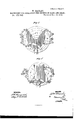
- Fig. 4 Sheet 2 is a top view of the machine adjusted for scalloping Vamps.
- Fig. 5, Sheet 2 is a top view of the machine adjusted for scalloping quarters.
- the object of this invention is to furnish an improved machine for holding the button-flies, Vamps, and quarters of shoes while being scalloped, and which shall be simple in construction and convenient in use, enabling the pieces to be readily put in and taken out, and holding them firrrly while being scalloped.
- the invention consists in the combination of the plate provided with the screw-socket, the stationary screw, and the set-screws, with the block and the bed-plate of the machine in the combination of the standards, provided with the screw-sockets and the set-screws, the slotted bars, the pivoted bars, and the holders with each other, and with the block; in the combination of the adjustable right-an gled bar, the pivoted lever, provided with the pivoted cross-bar, and the lever-cam, with the bed-plate and the block; and in the combination of the pivoted lever, the cord and treadie, and the spring, with the right-angled bar and the block, as hereinafter fully described.
- A is the bed-plate of the machine, the ends of which are bolted to the cross-bars of the two pairs of legs B, and to the rear part of which is attached a fifth leg, 0.
- the lower ends of the legs B have lugs, b, formed upon them, and are bolted to the bench, and the lower end of the leg 0 rests in a socket, c, attached to the bench.
- a hub, a In the center of the bed-plate A is formed a hub, a, in which is secured a screw, D, which passes up into a screw-socket, a, formed upon the center of a circular plate, E.
- the plate E is firmly secured to the bottom of the block F, upon the top of which the scalloping is done.
- the block F may be raised or lowered by turning it in one or the other direction upon the screw D.
- the block F is locked in position when adjusted by four setscrews, G, which pass up through screw-sockets a? in the bed-plate A, and the forward ends of which rest against the lower side of the plate E.
- a standard, H upon the upper ends of which are formed screw-sockets to receive the clamping-screws h, which pass through the slots of the bars I, and clamp said bars to the upper ends of the said standards H.
- each of the bars I Upon the ends of one side edge of each of the bars I are formed lugs, to which are pivoted the ends of bars J, the other ends of which are pivoted to a lug formed upon the lower part of the rear sides of the three armed plates or holders K.
- This construction enables the holders K to be adjusted according to the shape or size of the pieces to be scalloped.
- a grooved socket, 60 Upon the lower side of the forward part of the bed plate A is formed a grooved socket, 60 to receive the ribbed lower arm of the right-angled bar L, where it is secured in place adjustably by a set-screw, l.
- the other arm of the bar L projects upward along the side of the block 1*, and to the side of its upper end is pivoted a lever, M, to the forward end of which is pivoted a curved crossbar, N, to rest upon the pieces to be scalloped and hold them in place while being operated upon.
- the cross-barN of the lever M is held down upon the work by a cam-lever, O, which is pivoted to the outer side of the upper. end of the bar L, or to a short arm formed upon said end, so that its cam may act against the outer end of the said lever M.
- In the face of the cam of the lever O are formed notches 0, which engage with the end of the lever M and prevent it from slipping upon said lever when the machine is in use.
- a lever, P To the other end of -the bolt that pivots the lever M to the bar L, is pivoted a lever, P, the forward end of which projects above the block F, and to the outer end of which is attached the end of a cord, Q.
- the other end of the cord Q is attached to a treadle, R, pivoted to the floor, so that the operator by pressing upon the said treadle with his feet, can raise the forward end of the lever P from the work.
- the forward end of ⁇ the lever P is held down upon the work by a spring, S, attached to the upper end of the bar L.
- the lever P is designed for use in arranging thin pieces upon the block F, to leave both hands free to smooth out the said pieces. As each piece is arranged in place it is held with the hand while the forward end of the lever P is raised from beneath it by operating the treadle R, and is then forced down upon said piece by the spring S'as the treadle R is released. When not required for use the lever P may be allowed to hang down at the side of the block F. ⁇ 1Vhen the pieces have been properly secured in place, the scallops are cut with a properly-shaped cutter.
Landscapes
- Engineering & Computer Science (AREA)
- Mechanical Engineering (AREA)
- Ladders (AREA)
Description
2Sheets-Sheet1. W. MANLEY. MACHINERY FOR SCOLLOPING THE UPPERS OF BOOTS AND SHOES.. N 135 z48 Patented Dec. 12,1876.
TH E GRAPHIC GD-N-Y Z Sheets-Sheet 2 W. MANLE'Y.
MACHINERY FOR SOOLLOPING THE UPPERS OF BOOTS AND SHOES. Na.185,248, Patented Dec.12, 1876.
FIGE.
WILLIAM MANLEY, OF ROCHESTER, NEW YORK.
IMPROVEMENT IN MACHINERY FOR SCALLOPING THE UPPERS 0F BOOTS AND SHOES.
Specification forming part of Letters Patent No. 155,248, dated December 12, 1876; application filed October 23, 1876.
To all whom it may concern:
Be it known that I, \VILLIAM MANLEY, of Rochester, in the county of Monroe and State of New York, have invented a new and useful Improvement in Shoe-Scalloping Machine, of which the following is a specification:
Figure 1, Sheet 1. is a top view of my improved machine adjusted for scalloping the button-flies of shoes. Fig. 2, Sheet 1, is a side view of the same, part being broken away to show the construction. Fig. 3, Sheet 1 is a detail view of the adj listing-wrench. Fig. 4, Sheet 2, is a top view of the machine adjusted for scalloping Vamps. Fig. 5, Sheet 2, is a top view of the machine adjusted for scalloping quarters.
Similar letters of reference indicate corresponding parts.
The object of this invention is to furnish an improved machine for holding the button-flies, Vamps, and quarters of shoes while being scalloped, and which shall be simple in construction and convenient in use, enabling the pieces to be readily put in and taken out, and holding them firrrly while being scalloped.
The invention consists in the combination of the plate provided with the screw-socket, the stationary screw, and the set-screws, with the block and the bed-plate of the machine in the combination of the standards, provided with the screw-sockets and the set-screws, the slotted bars, the pivoted bars, and the holders with each other, and with the block; in the combination of the adjustable right-an gled bar, the pivoted lever, provided with the pivoted cross-bar, and the lever-cam, with the bed-plate and the block; and in the combination of the pivoted lever, the cord and treadie, and the spring, with the right-angled bar and the block, as hereinafter fully described.
A is the bed-plate of the machine, the ends of which are bolted to the cross-bars of the two pairs of legs B, and to the rear part of which is attached a fifth leg, 0. The lower ends of the legs B have lugs, b, formed upon them, and are bolted to the bench, and the lower end of the leg 0 rests in a socket, c, attached to the bench. In the center of the bed-plate A is formed a hub, a, in which is secured a screw, D, which passes up into a screw-socket, a, formed upon the center of a circular plate, E. The plate E is firmly secured to the bottom of the block F, upon the top of which the scalloping is done. By this construction the block F may be raised or lowered by turning it in one or the other direction upon the screw D. The block F is locked in position when adjusted by four setscrews, G, which pass up through screw-sockets a? in the bed-plate A, and the forward ends of which rest against the lower side of the plate E. Upon the rear leg B of each pair is formed, or to it is attached, a standard, H, upon the upper ends of which are formed screw-sockets to receive the clamping-screws h, which pass through the slots of the bars I, and clamp said bars to the upper ends of the said standards H. Upon the ends of one side edge of each of the bars I are formed lugs, to which are pivoted the ends of bars J, the other ends of which are pivoted to a lug formed upon the lower part of the rear sides of the three armed plates or holders K. This construction enables the holders K to be adjusted according to the shape or size of the pieces to be scalloped. Upon the lower side of the forward part of the bed plate A is formed a grooved socket, 60 to receive the ribbed lower arm of the right-angled bar L, where it is secured in place adjustably by a set-screw, l. The other arm of the bar L projects upward along the side of the block 1*, and to the side of its upper end is pivoted a lever, M, to the forward end of which is pivoted a curved crossbar, N, to rest upon the pieces to be scalloped and hold them in place while being operated upon. The cross-barN of the lever M is held down upon the work by a cam-lever, O, which is pivoted to the outer side of the upper. end of the bar L, or to a short arm formed upon said end, so that its cam may act against the outer end of the said lever M. In the face of the cam of the lever O are formed notches 0, which engage with the end of the lever M and prevent it from slipping upon said lever when the machine is in use.
In the side of the block F is formed a groove of sufficient size to receive the upright arm of the bar L, to enable it to be moved inward when small pieces are to be held. To the other end of -the bolt that pivots the lever M to the bar L, is pivoted a lever, P, the forward end of which projects above the block F, and to the outer end of which is attached the end of a cord, Q. The other end of the cord Q is attached to a treadle, R, pivoted to the floor, so that the operator by pressing upon the said treadle with his feet, can raise the forward end of the lever P from the work. The forward end of \the lever P is held down upon the work by a spring, S, attached to the upper end of the bar L. The lever P is designed for use in arranging thin pieces upon the block F, to leave both hands free to smooth out the said pieces. As each piece is arranged in place it is held with the hand while the forward end of the lever P is raised from beneath it by operating the treadle R, and is then forced down upon said piece by the spring S'as the treadle R is released. When not required for use the lever P may be allowed to hang down at the side of the block F. \1Vhen the pieces have been properly secured in place, the scallops are cut with a properly-shaped cutter.
Having thus described myinvention, I claim as new and desire to secure by Letters Patent 1. The combination of the plate E, provided with the screw-sockets e, the stationary screw D, and the set-screws G, with the block F, and the bed-plate A of the machine, substantially as herein shown and described.
2. The combination of the standards H, pro vided with the screw sockets and the setscrews h, the slotted bars I, the pivoted bars J, the holders K, and the block F, substantially as herein shown and described.
3. The combination of the adjustable rightangled bar L, the pivoted lever M, provided with the pivoted cross-bar N,'and the levercam O, with the bed-plate A, and the block F, substantially as herein shown and described.
4. The combination of the pivoted lever P,
the cord Q, and treadle R, and the spring S, with the right-angled bar L, and the block F, substantially as herein shown and described.
WILLIAM MANLEY.
Witnesses:
J AMES T. GRAHAM, 0. SEDGWIGK.
Publications (1)
| Publication Number | Publication Date |
|---|---|
| US185248A true US185248A (en) | 1876-12-12 |
Family
ID=2254653
Family Applications (1)
| Application Number | Title | Priority Date | Filing Date |
|---|---|---|---|
| US185248D Expired - Lifetime US185248A (en) | Improvement in machinery for scalloping the uppers of boots and shoes |
Country Status (1)
| Country | Link |
|---|---|
| US (1) | US185248A (en) |
-
0
- US US185248D patent/US185248A/en not_active Expired - Lifetime
Similar Documents
| Publication | Publication Date | Title |
|---|---|---|
| US199579A (en) | Improvement in machines for nailing and clamping picture-frames | |
| US185248A (en) | Improvement in machinery for scalloping the uppers of boots and shoes | |
| US352359A (en) | Apparatus for holding leather while being scalloped | |
| US211612A (en) | Improvement in dies for serrating the edges of uppers | |
| US195166A (en) | Improvement in jacks for shoe-makers | |
| US1633755A (en) | Cutting machine | |
| US231427A (en) | William j | |
| US329367A (en) | Machine for lasting boots or shoes | |
| US270498A (en) | Machine for trimming | |
| US488442A (en) | Lasting-machine | |
| US320733A (en) | Shoe-maker s rasping-tool | |
| US1556350A (en) | Shoe-repairing stand | |
| US187819A (en) | Improvement in lasting-jacks | |
| US564169A (en) | Rounding-out machine for boot or shoe soles | |
| US726745A (en) | Boot or shoe jack. | |
| US165595A (en) | Improvement in shoe-sole machines | |
| US385497A (en) | booth | |
| US974214A (en) | Shoe-creasing machine. | |
| US1131607A (en) | Sole-leather cutting and skiving machine. | |
| US1402533A (en) | Shoe-last-remodeling machine | |
| US151731A (en) | Improvement in machines for rubbing heel-seams | |
| US252525A (en) | Shoe-maker s jack | |
| US1109136A (en) | Heel-cutting apparatus. | |
| US2549A (en) | Cutting leather into soles | |
| US198622A (en) | Improvement in leather-crimping machines |