US1852489A - Heat exchanger - Google Patents
Heat exchanger Download PDFInfo
- Publication number
- US1852489A US1852489A US516487A US51648731A US1852489A US 1852489 A US1852489 A US 1852489A US 516487 A US516487 A US 516487A US 51648731 A US51648731 A US 51648731A US 1852489 A US1852489 A US 1852489A
- Authority
- US
- United States
- Prior art keywords
- conduit
- fluid
- tube
- rods
- heat
- Prior art date
- Legal status (The legal status is an assumption and is not a legal conclusion. Google has not performed a legal analysis and makes no representation as to the accuracy of the status listed.)
- Expired - Lifetime
Links
Images

Classifications
-
- F—MECHANICAL ENGINEERING; LIGHTING; HEATING; WEAPONS; BLASTING
- F28—HEAT EXCHANGE IN GENERAL
- F28D—HEAT-EXCHANGE APPARATUS, NOT PROVIDED FOR IN ANOTHER SUBCLASS, IN WHICH THE HEAT-EXCHANGE MEDIA DO NOT COME INTO DIRECT CONTACT
- F28D7/00—Heat-exchange apparatus having stationary tubular conduit assemblies for both heat-exchange media, the media being in contact with different sides of a conduit wall
- F28D7/02—Heat-exchange apparatus having stationary tubular conduit assemblies for both heat-exchange media, the media being in contact with different sides of a conduit wall the conduits being helically coiled
- F28D7/024—Heat-exchange apparatus having stationary tubular conduit assemblies for both heat-exchange media, the media being in contact with different sides of a conduit wall the conduits being helically coiled the conduits of only one medium being helically coiled tubes, the coils having a cylindrical configuration
Definitions
- This invention relates to heat exchangers
- the primary object of the present invention is to provide a new and improved construction of heat exchanger which is consiolerably more eflicient than prior apparatus of a similar nature heretofore used and known to me.
- a more specific object of the present invention is to provide, in a heat exchanger, an improved form of heat exchange unit, wherein the fluids will be caused to flow in heat interchanging relation for a comparatively great distance as compared to the actual length of the unit itself, and wherein the fluids are brought to and mainta ned in a highly turbulent state while flowing in heat interchanging relation, whereby maximum efficiency is insured for a heat exchanger of comparatively small size.
- Another object of the invention is to provide a heat exchange unit embodying a spirally twisted flattened tube or conduit through which one fluid is adapted to flow in a body of relatively thin Wide cross sectional area, and a further tube or conduit encasing the spirally twisted flattened tube or conduit and through which the other fluid is adapted to pass in spiral paths at opposite sides of the spirally twisted flattened tube, whereby heat is conveyed uniformly and rapidly through both walls of the spirally twisted flattened tube from one fluid to the other for effectively and uniformly cooling or heating the fluid passing through the spirally twisted flattened tube throughout the cross sectional area of the body of the latter liquid.
- My invention may be used for either heating or cooling fluids, either of a gaseous or liquid character.
- Figure 1 is a view partly in elevation and partly in section of a tube used to form the inner conduit of a heat exchange unit embodying the present invention.
- Figure 2 is an edge elevational view of the tube shown in Figure 1 after being partly flattened as the first step of forming the inner in Figure 5 after the inner conduit has been K twisted to a greater degree together with the associated coiled tubes.
- Figure 7 illustrates the device of Figure 6 arranged within an outer conduit to provide one form of completed heat exchange unit.
- Figure 8 is a transverse section on line 8-8 of Figure 7.
- Figure 9 is a vertical section of a heat exchanger employing a single unit of the form shown in Figure 7.
- Figure 10 is a view similar to Figure 9, showing a heat exchanger em loying a plurality of the units shown in igure 7, the units being connected in series.
- Figure 11 is a view similar to Fi ure 10 of a heat exchanger employing a purality of the units shown in Figure 7, the units being connected in parallel.
- Figure 12 is a view similar to Figure 7 of a modified form of heat exchange unit embodying the present invention.
- Figure 13 is a fragmentary view partly in elevation and partly in section showing a portion of one of the tubes coiled about the inner conduit of the unit shown in Figure 12, and illustrating clearly the manner in which a strand of wire is spirally wound about each of these tubes.
- Figure 14 is a transverse section on line 1414 of Figure 12;
- Figure 15 is a view similar to Figure 14, showing a modification of the unit of Figure 12 wherein the rods coiled about the inner conduit are solid instead of being in the form of hollow rods or tubes.
- the present invention in its broadest aspect contemplates the provision of a heat exchange unit including an inner conduit 5 in the form of a flattened spirally twisted tube of heat conducting material, and an outer tube or conduit 6 snugly encasing the spirally twisted flattened tube or inner conduit 5.
- the tube forming the conduit 5 is flattened so as to leave a thin wide passage through which one of the fluids may flow in a body of relatively thin and wide cross sectional area.
- This provides the conduit 5 with wide opposed walls which are subjected throughout their width to the heating or cooling action of the other fluid as it flows through the outer conduit 6 between the latter and the inner conduit 5. In this way, rapid and eflicient transfer of heat is caused to take place with respect to the two fluids,
- the two fluids are caused to travel in a relatively long spiral path for In flowing spirally, the fluids are brought to and maintained at a highly turbulent state as distinguished from a steady stream, thus maintainmg both liquids in a condition where uniform exchange of heat takes place in a most 5 a well known feature in connection with couneflicient manner.
- the fluids are referably caused to flow through the con nits in opposite directions,
- I preferably take a ength of cylindrical tubing as indicated at 511 in Figure 1, and flatten the same throughout the major portion of its length as indicated by dotted lines in Figure 1 and shown by full lines in Figures 2 and 3. This leaves a thin wide passage 5 through i which the fluid may pass, and provides the tube with relatively wide opposed walls 5".
- the flattened tube is then subjected to an axial twisting action while being maintained ure 4 wherein the major intermediate port1on under slight longitudinal tension, thereby bringing the same to the form shown in Figof the flattened tube is spirally twisted.
- the flattened end of the tube 5?) may then be suitably returned to cylindrical form and the adjacent ends of the rod 7 separated as shown in Figure 7 to complete the assembly of the unit. It will be found in constructing the element of Fi re 6 that the rods 7 will roject a slight istance beyond the tube 5 so that a slight space will be left between the latter and the outer conduit 6. This insures flow of fluid longitudinally of the outer conduit across the spiral rib portions of the tube 5?) and across the rods 7, while other portions of the fluid will break up and flow in s iral paths so as to follow the twisted form 0 the tube 5b and the coiled form of the rods 7. The result of this action is that the fluid passing through the outer conduit 6 between the latter and the inner conduit will be brought to a very highly turbulent state, thus producing a more efiicient heat exchanging action.
- the rods 7 may be of hollow form or in the nature of tubes through which some of the fluid may pass in addition to passing through the conduit 6 between the latter and the mner conduit 5 when still greater heat exchanging efliciency is required.
- the rods 7 may be solid so that the unit may be adapted only for passage of one fluid between the conduits 5 and 6 and for the assa of the other fluid through the condult 5.
- the rods 7 may be further provided with .a helical external winding of wire as at 8.
- FIGS 9, 10 and 11 are included to merely show in a general way how heat exchange units embodying the present invention may be em loyed in a complete heat exchanger
- a sing e unit is employed, the condiiit 6 being placed within a casing 9 having headers 10 and 11 at opposite ends thereof with which the opposite ends of the conduit 6 respectively communicate, as do also the opposite ends of the rods 7 when in tubular form or in the nature of tubes.
- These headers are respectively provided with fluid discharge and supply pipes 12 and 13, while the opposite ends of the inner conduit extend through the headers for connection with pipes leading to a source of supply of another fluid and to a point of discharge for such fluid after being heated or cooled.
- the space between the casing 9 and the outer conduit 6 of the heat exchange unit may be filled with suitable insulating material 14. While the same has not been shown, it is obvious that the conduits or pipes outside of the heat exchanger may be suitably insulated, together with the headers 10and ll.
- Figure 10 is very similar to that described in connection with Fig ure 9 except that a plurality of the heat ex change units are employed within the casing 9a and the conduits 5 of the several units are connected in series as at 15. This use of a pluarlity of units will be required where greater heat exchanging eficiency and the cooling or heating of a greater volume of fluid is required.
- Figure 11 The construction of Figure 11 is also quite similar to thatot Figure 10, the diflerence being that the inner conduits 5 of the several heat exchange units are connected in parallel. lln other words, adjacent ends of the conduits 5 of the several units are connected together and to a common fluid supply pipe it, while the opposite adjacent ends of said inner conduits 5 are similarly connected together and to a common outlet pi e 17.
- the tubes 7 and outer conduits 6 o the units shown in Figures 10 and 11 all open at their opposite ends respectively within the headers lilo and 11a, and these headers are provided respectively with fluid discharge and supply pipes 12a and 13a.
- an inner conduit in the form of a flattened tube compactly spirally twisted, an outer cylindrical conduit co-axial with and snugly encasing the inner conduit, said conduits being in non-communicating relation, means to supply said outer conduit with a fluid, and means for separately supplying the inner conduit with a fluid adapted to flow in heat-interchanging relation with the first-named fluid.
- a heat exchange unit comprising an inner conduit in the form of a flattened spirally twisted tube, rods arranged at opposite sides of said tube and coiled about the latter to intimately follow the twists of the same, and an outer conduit snugly encasing the inner conduit and rods.
- a heat exchange unit comprising an inner conduit in the form of a flattened spirally twisted tube, rods arranged at opposite sides of said tube and coiled about the latter to intimately follow the twists of the same, an outer conduit snugly encasing the inner conduit and rods, and wire strands helically Wound about said rods with the convolutions thereof spaced apart.
- a heat exchange unit comprising an inner conduit in the form of a flattened spirally twisted tube, rods arranged at opposite sides of said tube and coiled about the latter to intimately follow the twists of the same, an outer conduit snugly encasing the inner conduit and rods, wire strands helically wound about said rods with the convolutions thereof spaced apart, said rods being in the form of tubes or hollow for the flow of fluid therethrough.
- an inner conduit in the term of a flattened spirally twisted tube, an outer cylindrical conduit coaxial with and snugly encasing said inner conduit, and means for passing fluids in opposite directions through said conduits.
- an inner conduit in the form of a flattened spirally twisted tube, tubular rods arranged at opposite sides of and snugly coiled about said inner conduit to follow the twists thereof, an outer cylindrical conduit snugly encasing the inner conduit and tubular rods, means to su ply said tubular rods and outer conduit witli a fluid, and means for separately supplying the inner conduit with a fluid adapted to flow in heat- 5 Entei'changing relation with the first-named 7.
- a heat exchange unit including an inner conduit in the form of a flattened spirally twisted tube having a spiral m passage of relatively thin wide cross sectional area through which a fluid is adapted to flow for being brought to and maintained in a highly turbulent state, and an outer cylindrlcal conduit co-axial with and snugly en- 5 casing the inner conduit and through another fluid is adapted to flow in heat-interchan ing relation with the walls of the inner conduit.
- a fluid conduit in the form of a flattened spirally twisted tube 6 of heat-conducting material said conduit having opposed Wide walls defining a fluid passage of relatively thin and wide cross sectional area and of spiral form, said walls being concaved, and rods arranged at oppo- 25 site sides of and coiled about said conduit to follow the twists thereof in intimate contact with the concave walls of said conduit.
- a fluid conduit in the form of a flattened spirally twisted tube 36 of heat-conducting material said conduit having opposed wide walls defining a fluid passage of relatively thin and wide cross sectional area and of spiral form, said walls being concaved, rods arranged at opposite sides 5 of and coiled about said conduit to follow the twists thereof in intimate contact with the concave walls of said conduit, and an outer fluid conduit snugly encasing the firstnamed conduit and the rods.
- a fluid conduit in the form of a flattened spirally twisted tube of heat-conducting material said conduit having opposed wide walls defining a fluid passage of relatively thin and wide cross sec- 45 tional area and of spiral form, said walls being concaved, rods arranged at opposite sides of and coiled about said conduit to follow the twists thereof in intimate contact with the concave walls of said conduit, an outer "5 0 fluid conduit snugl encasing the first-named conduit and the re s, said rods being of tubular form to provide further conduits for the same fluid as is caused to flow between the first-named conduits.
Description
E. G. SULLIVAN HEAT EXCHANGER April 5 193" Filed Feb. 17, 1951 4 Sheets-Sheet l Edward 6'. SaZZiwam,
I N 1 'EN TOR.
BY Q jr A TTORVE Y.
April 5, 11932" E. G. SULLi VAN HEAT EXCHANGER Filed Feb. 17, 1951 4 Sheetsheet 2 IN 1 'EN T OR.
17. 1931 4 Sheets-Sheet 3 ,Fdwarc/ G. 324 ZZiWQW,
1N! 'ENTOR A TTORNEY.
April 1932 E. G. SULLIVAN I 89 HEAT EXCHANGER Filed Feb. 17, 1931 4 Sheets-Sheet 4 1N] "EN TOR.
Patented Apr. 5, 1932 UNITED STATES PATENT OFFICE EDWARD G. SULLIVAN, OF A'MARILLO, TEXAS, ASSIGNOR TO JOSEPH S. BELT, OF AMARILLO, TEXAS HEAT EXCHANGER Application filed February 17, 1931. Serial No. 516,487.
This invention relates to heat exchangers,
or to an apparatus for use in transferring,
heat from one fluid to another fluid, through an intervening heat conducting wall.
The primary object of the present invention is to provide a new and improved construction of heat exchanger which is consiolerably more eflicient than prior apparatus of a similar nature heretofore used and known to me.
A more specific object of the present invention is to provide, in a heat exchanger, an improved form of heat exchange unit, wherein the fluids will be caused to flow in heat interchanging relation for a comparatively great distance as compared to the actual length of the unit itself, and wherein the fluids are brought to and mainta ned in a highly turbulent state while flowing in heat interchanging relation, whereby maximum efficiency is insured for a heat exchanger of comparatively small size.
Another object of the invention is to provide a heat exchange unit embodying a spirally twisted flattened tube or conduit through which one fluid is adapted to flow in a body of relatively thin Wide cross sectional area, and a further tube or conduit encasing the spirally twisted flattened tube or conduit and through which the other fluid is adapted to pass in spiral paths at opposite sides of the spirally twisted flattened tube, whereby heat is conveyed uniformly and rapidly through both walls of the spirally twisted flattened tube from one fluid to the other for effectively and uniformly cooling or heating the fluid passing through the spirally twisted flattened tube throughout the cross sectional area of the body of the latter liquid.
My invention may be used for either heating or cooling fluids, either of a gaseous or liquid character.
The nature of the present invention as well as the objects and advantages thereof will be more clearly apparent from the following description taken in connection with the accompanying drawings, in which:
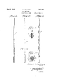
Figure 1 is a view partly in elevation and partly in section of a tube used to form the inner conduit of a heat exchange unit embodying the present invention.
Figure 2 is an edge elevational view of the tube shown in Figure 1 after being partly flattened as the first step of forming the inner in Figure 5 after the inner conduit has been K twisted to a greater degree together with the associated coiled tubes.
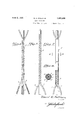
Figure 7 illustrates the device of Figure 6 arranged within an outer conduit to provide one form of completed heat exchange unit.
Figure 8 is a transverse section on line 8-8 of Figure 7.
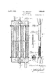
Figure 9 is a vertical section of a heat exchanger employing a single unit of the form shown in Figure 7.
Figure 10 is a view similar to Figure 9, showing a heat exchanger em loying a plurality of the units shown in igure 7, the units being connected in series.
Figure 11 is a view similar to Fi ure 10 of a heat exchanger employing a purality of the units shown in Figure 7, the units being connected in parallel.
Figure 12 is a view similar to Figure 7 of a modified form of heat exchange unit embodying the present invention.
Figure 13 is a fragmentary view partly in elevation and partly in section showing a portion of one of the tubes coiled about the inner conduit of the unit shown in Figure 12, and illustrating clearly the manner in which a strand of wire is spirally wound about each of these tubes.
Figure 14 is a transverse section on line 1414 of Figure 12; and
Figure 15 is a view similar to Figure 14, showing a modification of the unit of Figure 12 wherein the rods coiled about the inner conduit are solid instead of being in the form of hollow rods or tubes.
The present invention in its broadest aspect contemplates the provision of a heat exchange unit including an inner conduit 5 in the form of a flattened spirally twisted tube of heat conducting material, and an outer tube or conduit 6 snugly encasing the spirally twisted flattened tube or inner conduit 5. As shown in iiigure 3, the tube forming the conduit 5 is flattened so as to leave a thin wide passage through which one of the fluids may flow in a body of relatively thin and wide cross sectional area. This provides the conduit 5 with wide opposed walls which are subjected throughout their width to the heating or cooling action of the other fluid as it flows through the outer conduit 6 between the latter and the inner conduit 5. In this way, rapid and eflicient transfer of heat is caused to take place with respect to the two fluids,
' a unit of given lesser length.
and due to the spiral form of the inner conduit and the fact that the outer conduit 6 snugly encases the same, the two fluids are caused to travel in a relatively long spiral path for In flowing spirally, the fluids are brought to and maintained at a highly turbulent state as distinguished from a steady stream, thus maintainmg both liquids in a condition where uniform exchange of heat takes place in a most 5 a well known feature in connection with couneflicient manner. As is Well known in connection with other types of heat exchangers, the fluids are referably caused to flow through the con nits in opposite directions,
tercurrent heat exchangers.
In formin the inner 'conduit 5, I preferably take a ength of cylindrical tubing as indicated at 511 in Figure 1, and flatten the same throughout the major portion of its length as indicated by dotted lines in Figure 1 and shown by full lines in Figures 2 and 3. This leaves a thin wide passage 5 through i which the fluid may pass, and provides the tube with relatively wide opposed walls 5".
The flattened tube is then subjected to an axial twisting action while being maintained ure 4 wherein the major intermediate port1on under slight longitudinal tension, thereby bringing the same to the form shown in Figof the flattened tube is spirally twisted.
While in some uses a heat exchange unit consisting only of the inner conduit 5 and outer conduit 6 would prove as eificient as necessary or desired, there are some uses in which more eflicient heat interchange is necessa In this event, I preferably arrange rods which may be hollow at opposite sldes -.of the tube when. spirally twisted as shown the tube'5b in cylindrical form and havin the other end thereof flattened, the ends 0 the rods 7 may be arranged parallel with and at opposite sides of the flattened end of the tube as shown in Figure 6 so that the element shown in the latter figure may be readily inserted within the outer conduit 6. The flattened end of the tube 5?) may then be suitably returned to cylindrical form and the adjacent ends of the rod 7 separated as shown in Figure 7 to complete the assembly of the unit. It will be found in constructing the element of Fi re 6 that the rods 7 will roject a slight istance beyond the tube 5 so that a slight space will be left between the latter and the outer conduit 6. This insures flow of fluid longitudinally of the outer conduit across the spiral rib portions of the tube 5?) and across the rods 7, while other portions of the fluid will break up and flow in s iral paths so as to follow the twisted form 0 the tube 5b and the coiled form of the rods 7. The result of this action is that the fluid passing through the outer conduit 6 between the latter and the inner conduit will be brought to a very highly turbulent state, thus producing a more efiicient heat exchanging action.
As shown in Figure 5, the rods 7 may be of hollow form or in the nature of tubes through which some of the fluid may pass in addition to passing through the conduit 6 between the latter and the mner conduit 5 when still greater heat exchanging efliciency is required. However, as shown in Figure 15, the rods 7 may be solid so that the unit may be adapted only for passage of one fluid between the conduits 5 and 6 and for the assa of the other fluid through the condult 5. 11 either case, the rods 7 may be further provided with .a helical external winding of wire as at 8.
This helical winding of wire will be used so that its convolutions are spaced a art, and the action of the winding is to sti 1 further break up the fluid as it flows between the conduits, thereby still further increasing the degree of turbulence of the fluid. The rods in solid form are indicated at 7a in Figure 1-5. There are a great variety of ways in which heat exchange units constructed in accordance with the present invention may be used in providing a heat exchange apparatus, and when using the apparatus for the cooling of one gas passing t rough the inner conduit 5 by means of another gas passin between the conduits, such gases are usua 1y under considerable ressure. When under pressure, the flow of the gas is forced and the breaking up of the gas is enhanced so that a big degree of turbulence is insured.
Figures 9, 10 and 11 are included to merely show in a general way how heat exchange units embodying the present invention may be em loyed in a complete heat exchanger,
with t e conduits properly associated with y difl'erent sources of fluid suppl and exhaust or outlet. In Fi ure 9, a sing e unit is employed, the condiiit 6 being placed within a casing 9 having headers 10 and 11 at opposite ends thereof with which the opposite ends of the conduit 6 respectively communicate, as do also the opposite ends of the rods 7 when in tubular form or in the nature of tubes. These headers are respectively provided with fluid discharge and supply pipes 12 and 13, while the opposite ends of the inner conduit extend through the headers for connection with pipes leading to a source of supply of another fluid and to a point of discharge for such fluid after being heated or cooled. The space between the casing 9 and the outer conduit 6 of the heat exchange unit may be filled with suitable insulating material 14. While the same has not been shown, it is obvious that the conduits or pipes outside of the heat exchanger may be suitably insulated, together with the headers 10and ll.
'lhe construction of Figure 10 is very similar to that described in connection with Fig ure 9 except that a plurality of the heat ex change units are employed within the casing 9a and the conduits 5 of the several units are connected in series as at 15. This use of a pluarlity of units will be required where greater heat exchanging eficiency and the cooling or heating of a greater volume of fluid is required.
The construction of Figure 11 isalso quite similar to thatot Figure 10, the diflerence being that the inner conduits 5 of the several heat exchange units are connected in parallel. lln other words, adjacent ends of the conduits 5 of the several units are connected together and to a common fluid supply pipe it, while the opposite adjacent ends of said inner conduits 5 are similarly connected together and to a common outlet pi e 17. The tubes 7 and outer conduits 6 o the units shown in Figures 10 and 11 all open at their opposite ends respectively within the headers lilo and 11a, and these headers are provided respectively with fluid discharge and supply pipes 12a and 13a.
lit is obvious that the same form of heat exchangers may be constructed when the units are devoid of the spiral or coiled rods i, or if such rods are used in solid form as shown in Figure 15. It is also noted that the passage through the spirally twisted inner conduit is somewhat exaggerated in the drawings for sake of clearness. In actual practice, the tube 5a will be flattened so that a very time or thin passage is provided at 5' between the opposed wide walls 5". in tightly twisting the parts to the final form of Figure 6, the opposite edge portions of the flattened tube will swell slightly so that the tube M will be brought into concave form at opposite sides for fitting the contacting curved sides of the rods or tubes 7 to a great extent. This is indicated generally in Figures 8 and 15.
From the foregoing description it is believed that the construction and operation, as well as the advantages of the present invention will be readily understood and appreciated by those skilled in the art. It will be particularly understood that various changes and modifications of the invention are contemplated, and that it is fully appreciated that the invention may be adapted to various uses and types of construction without departing from the spirit and scope of the invention as claimed.
What I claim as new is:
1. In a heat exchanger, an inner conduit in the form of a flattened tube compactly spirally twisted, an outer cylindrical conduit co-axial with and snugly encasing the inner conduit, said conduits being in non-communicating relation, means to supply said outer conduit with a fluid, and means for separately supplying the inner conduit with a fluid adapted to flow in heat-interchanging relation with the first-named fluid.
2. In a heat exchanger, a heat exchange unit comprising an inner conduit in the form of a flattened spirally twisted tube, rods arranged at opposite sides of said tube and coiled about the latter to intimately follow the twists of the same, and an outer conduit snugly encasing the inner conduit and rods.
3. In a heat exchanger, a heat exchange unit comprising an inner conduit in the form of a flattened spirally twisted tube, rods arranged at opposite sides of said tube and coiled about the latter to intimately follow the twists of the same, an outer conduit snugly encasing the inner conduit and rods, and wire strands helically Wound about said rods with the convolutions thereof spaced apart.
4.. In a heat exchanger, a heat exchange unit comprising an inner conduit in the form of a flattened spirally twisted tube, rods arranged at opposite sides of said tube and coiled about the latter to intimately follow the twists of the same, an outer conduit snugly encasing the inner conduit and rods, wire strands helically wound about said rods with the convolutions thereof spaced apart, said rods being in the form of tubes or hollow for the flow of fluid therethrough.
5. In a heat exchanger, an inner conduit in the term of a flattened spirally twisted tube, an outer cylindrical conduit coaxial with and snugly encasing said inner conduit, and means for passing fluids in opposite directions through said conduits.
6. In a heat exchanger, an inner conduit in the form of a flattened spirally twisted tube, tubular rods arranged at opposite sides of and snugly coiled about said inner conduit to follow the twists thereof, an outer cylindrical conduit snugly encasing the inner conduit and tubular rods, means to su ply said tubular rods and outer conduit witli a fluid, and means for separately supplying the inner conduit with a fluid adapted to flow in heat- 5 Entei'changing relation with the first-named 7. In a heat exchanger, a heat exchange unit including an inner conduit in the form of a flattened spirally twisted tube having a spiral m passage of relatively thin wide cross sectional area through which a fluid is adapted to flow for being brought to and maintained in a highly turbulent state, and an outer cylindrlcal conduit co-axial with and snugly en- 5 casing the inner conduit and through another fluid is adapted to flow in heat-interchan ing relation with the walls of the inner conduit.
8. In a heat exchanger, a fluid conduit in the form of a flattened spirally twisted tube 6 of heat-conducting material, said conduit having opposed Wide walls defining a fluid passage of relatively thin and wide cross sectional area and of spiral form, said walls being concaved, and rods arranged at oppo- 25 site sides of and coiled about said conduit to follow the twists thereof in intimate contact with the concave walls of said conduit.
9. In a heat exchanger, a fluid conduit in the form of a flattened spirally twisted tube 36 of heat-conducting material, said conduit having opposed wide walls defining a fluid passage of relatively thin and wide cross sectional area and of spiral form, said walls being concaved, rods arranged at opposite sides 5 of and coiled about said conduit to follow the twists thereof in intimate contact with the concave walls of said conduit, and an outer fluid conduit snugly encasing the firstnamed conduit and the rods.-
0 10. In a heat exchanger, a fluid conduit in the form of a flattened spirally twisted tube of heat-conducting material, said conduit having opposed wide walls defining a fluid passage of relatively thin and wide cross sec- 45 tional area and of spiral form, said walls being concaved, rods arranged at opposite sides of and coiled about said conduit to follow the twists thereof in intimate contact with the concave walls of said conduit, an outer "5 0 fluid conduit snugl encasing the first-named conduit and the re s, said rods being of tubular form to provide further conduits for the same fluid as is caused to flow between the first-named conduits.
'55 In testimony whereof aifix my signature.
\ EDWARD G. SULLIVAN.
Priority Applications (1)
| Application Number | Priority Date | Filing Date | Title |
|---|---|---|---|
| US516487A US1852489A (en) | 1931-02-17 | 1931-02-17 | Heat exchanger |
Applications Claiming Priority (1)
| Application Number | Priority Date | Filing Date | Title |
|---|---|---|---|
| US516487A US1852489A (en) | 1931-02-17 | 1931-02-17 | Heat exchanger |
Publications (1)
| Publication Number | Publication Date |
|---|---|
| US1852489A true US1852489A (en) | 1932-04-05 |
Family
ID=24055809
Family Applications (1)
| Application Number | Title | Priority Date | Filing Date |
|---|---|---|---|
| US516487A Expired - Lifetime US1852489A (en) | 1931-02-17 | 1931-02-17 | Heat exchanger |
Country Status (1)
| Country | Link |
|---|---|
| US (1) | US1852489A (en) |
Cited By (16)
| Publication number | Priority date | Publication date | Assignee | Title |
|---|---|---|---|---|
| US2441270A (en) * | 1944-09-16 | 1948-05-11 | Peerless Of America | Refrigerating system and heat exchanger therefor |
| US2449822A (en) * | 1942-12-11 | 1948-09-21 | Svenska Cellulosa Ab | Heat exchanging apparatus |
| US3201861A (en) * | 1960-03-31 | 1965-08-24 | Fromson H A | Method of making a double-walled tube |
| US4398567A (en) * | 1979-10-15 | 1983-08-16 | Cinderella Ab | Conduit device |
| US4589481A (en) * | 1982-06-29 | 1986-05-20 | Ab Zander & Ingestrom | Tube heat exchanger |
| US4635711A (en) * | 1985-02-15 | 1987-01-13 | Harsco Corporation | Double wall heat exchanger |
| WO1987000912A1 (en) * | 1985-08-08 | 1987-02-12 | Interpat Service Ag | Method and means for cleaning/condensing/vaporizing a flow of gas or liquid |
| EP0468046A1 (en) * | 1990-02-09 | 1992-01-29 | Columbia Gas System Service Corporation | Heat transfer apparatus for heat pumps |
| WO2007106669A2 (en) * | 2006-03-10 | 2007-09-20 | Briselden, Thomas, D. | Heat exchanging insert and method for fabricating same |
| US20090031855A1 (en) * | 2007-08-03 | 2009-02-05 | Ramberg Charles E | Porous bodies and methods |
| US20110203766A1 (en) * | 2010-02-23 | 2011-08-25 | Robert Jensen | Twisted conduit for geothermal heating and cooling systems |
| US20120186776A1 (en) * | 2010-02-23 | 2012-07-26 | Robert Jensen | Twisted conduit for geothermal heating and cooling systems |
| US8277743B1 (en) | 2009-04-08 | 2012-10-02 | Errcive, Inc. | Substrate fabrication |
| US8359829B1 (en) | 2009-06-25 | 2013-01-29 | Ramberg Charles E | Powertrain controls |
| US20170191762A1 (en) * | 2016-01-04 | 2017-07-06 | United Technologies Corporation | Heat exchanger for cooling medium temperature reduction |
| US9833932B1 (en) | 2010-06-30 | 2017-12-05 | Charles E. Ramberg | Layered structures |
-
1931
- 1931-02-17 US US516487A patent/US1852489A/en not_active Expired - Lifetime
Cited By (36)
| Publication number | Priority date | Publication date | Assignee | Title |
|---|---|---|---|---|
| US2449822A (en) * | 1942-12-11 | 1948-09-21 | Svenska Cellulosa Ab | Heat exchanging apparatus |
| US2441270A (en) * | 1944-09-16 | 1948-05-11 | Peerless Of America | Refrigerating system and heat exchanger therefor |
| US3201861A (en) * | 1960-03-31 | 1965-08-24 | Fromson H A | Method of making a double-walled tube |
| US4398567A (en) * | 1979-10-15 | 1983-08-16 | Cinderella Ab | Conduit device |
| US4589481A (en) * | 1982-06-29 | 1986-05-20 | Ab Zander & Ingestrom | Tube heat exchanger |
| US4635711A (en) * | 1985-02-15 | 1987-01-13 | Harsco Corporation | Double wall heat exchanger |
| WO1987000912A1 (en) * | 1985-08-08 | 1987-02-12 | Interpat Service Ag | Method and means for cleaning/condensing/vaporizing a flow of gas or liquid |
| EP0468046A1 (en) * | 1990-02-09 | 1992-01-29 | Columbia Gas System Service Corporation | Heat transfer apparatus for heat pumps |
| EP0468046A4 (en) * | 1990-02-09 | 1995-02-22 | Columbia Gas Syst | Heat transfer apparatus for heat pumps |
| US5533362A (en) * | 1990-02-09 | 1996-07-09 | Columbia Gas Of Ohio, Inc. | Heat transfer apparatus for heat pumps |
| WO2007106669A2 (en) * | 2006-03-10 | 2007-09-20 | Briselden, Thomas, D. | Heat exchanging insert and method for fabricating same |
| US20070224565A1 (en) * | 2006-03-10 | 2007-09-27 | Briselden Thomas D | Heat exchanging insert and method for fabricating same |
| WO2007106669A3 (en) * | 2006-03-10 | 2008-11-06 | Briselden Thomas D | Heat exchanging insert and method for fabricating same |
| US8162040B2 (en) * | 2006-03-10 | 2012-04-24 | Spinworks, LLC | Heat exchanging insert and method for fabricating same |
| US8097220B2 (en) | 2007-08-03 | 2012-01-17 | Errcive, Inc. | Porous bodies and methods |
| US8361406B2 (en) | 2007-08-03 | 2013-01-29 | Errcive, Inc. | Porous bodies and methods |
| US8821803B2 (en) | 2007-08-03 | 2014-09-02 | Errcive, Inc. | Porous bodies and methods |
| US8092753B2 (en) | 2007-08-03 | 2012-01-10 | Errcive, Inc. | Porous bodies and methods |
| US20100133106A1 (en) * | 2007-08-03 | 2010-06-03 | Ramberg Charles E | Porous Bodies and Methods |
| US20090031855A1 (en) * | 2007-08-03 | 2009-02-05 | Ramberg Charles E | Porous bodies and methods |
| US8221694B2 (en) | 2007-08-03 | 2012-07-17 | Errcive, Inc. | Porous bodies and methods |
| US8623287B2 (en) | 2007-08-03 | 2014-01-07 | Errcive, Inc. | Porous bodies and methods |
| US8551216B2 (en) | 2007-08-03 | 2013-10-08 | Errcive, Inc. | Porous bodies and methods |
| US8361420B2 (en) | 2007-08-03 | 2013-01-29 | Errcive, Inc. | Porous bodies and methods |
| US7981375B2 (en) | 2007-08-03 | 2011-07-19 | Errcive, Inc. | Porous bodies and methods |
| US8277743B1 (en) | 2009-04-08 | 2012-10-02 | Errcive, Inc. | Substrate fabrication |
| US8679418B2 (en) | 2009-04-08 | 2014-03-25 | Errcive, Inc. | Substrate fabrication |
| US9511345B1 (en) | 2009-04-08 | 2016-12-06 | Errcive, Inc. | Substrate fabrication |
| US8359829B1 (en) | 2009-06-25 | 2013-01-29 | Ramberg Charles E | Powertrain controls |
| US20120186776A1 (en) * | 2010-02-23 | 2012-07-26 | Robert Jensen | Twisted conduit for geothermal heating and cooling systems |
| US8640765B2 (en) * | 2010-02-23 | 2014-02-04 | Robert Jensen | Twisted conduit for geothermal heating and cooling systems |
| US20110203766A1 (en) * | 2010-02-23 | 2011-08-25 | Robert Jensen | Twisted conduit for geothermal heating and cooling systems |
| US9109813B2 (en) * | 2010-02-23 | 2015-08-18 | Robert Jensen | Twisted conduit for geothermal heating and cooling systems |
| US9833932B1 (en) | 2010-06-30 | 2017-12-05 | Charles E. Ramberg | Layered structures |
| US20170191762A1 (en) * | 2016-01-04 | 2017-07-06 | United Technologies Corporation | Heat exchanger for cooling medium temperature reduction |
| US11041677B2 (en) * | 2016-01-04 | 2021-06-22 | Raytheon Technologies Corporation | Heat exchanger for cooling medium temperature reduction |
Similar Documents
| Publication | Publication Date | Title |
|---|---|---|
| US1852489A (en) | Heat exchanger | |
| US1852490A (en) | Heat exchanger | |
| US2373218A (en) | Oil cooler tube | |
| US2508247A (en) | Heat interchanger | |
| US2663321A (en) | Tubular heat transfer apparatus | |
| US2341319A (en) | Heat exchanger | |
| US2471317A (en) | Heat exchanger | |
| US3048021A (en) | Joule-thomson effect gas liquefier | |
| US6626235B1 (en) | Multi-tube heat exchanger with annular spaces | |
| CH643342A5 (en) | PIPELINE SYSTEM FOR DEEP COLD AND / OR LIQUID GASES. | |
| JPS59185995A (en) | Hybrid spiral type turbulence inducing body for heat exchanger | |
| TW201346206A (en) | Heat transfer pipe and heat exchanger using the same | |
| US2503595A (en) | Refrigerating apparatus | |
| US3127200A (en) | Sayag | |
| CN107228581A (en) | Sub-thread stream reduced pipe wound tube heat exchanger | |
| CN203489539U (en) | Heat exchanger | |
| US2307924A (en) | Liquid heater | |
| US1673918A (en) | Heat exchanger | |
| US3401682A (en) | Regenerative tube-bundle heat exchanger having screw-like flat-tened tubes helicallywound in spaced-apart relationship | |
| US2081043A (en) | Heat exchanger | |
| US1979859A (en) | Tube for boilers, heat exchangers, and the like | |
| US1935412A (en) | Fluid cooler | |
| US1394311A (en) | Radiator-core | |
| CN108581264A (en) | A kind of double-layer bend processing method | |
| GB1323943A (en) | Heat-exchanger |