US1852465A - Seat - Google Patents
Seat Download PDFInfo
- Publication number
- US1852465A US1852465A US390186A US39018629A US1852465A US 1852465 A US1852465 A US 1852465A US 390186 A US390186 A US 390186A US 39018629 A US39018629 A US 39018629A US 1852465 A US1852465 A US 1852465A
- Authority
- US
- United States
- Prior art keywords
- section
- seat
- movable
- sections
- lazy tongs
- Prior art date
- Legal status (The legal status is an assumption and is not a legal conclusion. Google has not performed a legal analysis and makes no representation as to the accuracy of the status listed.)
- Expired - Lifetime
Links
- 238000010276 construction Methods 0.000 description 4
- 238000006073 displacement reaction Methods 0.000 description 2
- 101150076104 EAT2 gene Proteins 0.000 description 1
Images
Classifications
-
- B—PERFORMING OPERATIONS; TRANSPORTING
- B60—VEHICLES IN GENERAL
- B60N—SEATS SPECIALLY ADAPTED FOR VEHICLES; VEHICLE PASSENGER ACCOMMODATION NOT OTHERWISE PROVIDED FOR
- B60N2/00—Seats specially adapted for vehicles; Arrangement or mounting of seats in vehicles
- B60N2/75—Arm-rests
- B60N2/753—Arm-rests movable to an inoperative position
- B60N2/76—Arm-rests movable to an inoperative position in a recess of the cushion
Definitions
- This invention relatesto an improvement in seats, and more particularly to the provision of a movable section which can be shifted into an oifset position relatively to ,El other sections of the seat to form an arm rest.
- An object of the invention is to provide a novel and improved seat for use in automobiles or other places.
- Another object is to provide a seat having one or more stationary sections and a section which normally extends continuously with said stationary section or sections and forms a part of the seat and which is movable into another position relatively to the other section or sections of the seat to form an arm rest.
- an improved seat having a section which normally occupies a position between or at one side of other sections of a seat and forms a part of said seat, and in which position it has the appearance of being a continuous part of said seat, and which may be easily and quickly moved out of its normal position into an offset position for use as an arm rest; also to provide a movable section, the movements of which to and from its arm rest position can be effected by a simple movement of translation; also to provide means for shifting the movable seat section which may be concealed beneath or back of the movable sec tion so as to be inconspicuous when the section is in its offset position, and which will be entirely concealed by said section when the latter is occupying its normal position.
- Another object of the invention therefore is to provide an improved seat having a section which is movable into and out of a posi- 3, 1929. Serial No. 390,186.
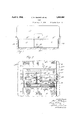
- Fig. 1 is a front elevation of an improved seat embodying our invention, showing the base or support on which it is mounted partly in section.
- Fig. 2 is a fragmentarv plan view showing the movable section of the seat partly broken away and in section, and with the back section omitted.
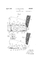
- Fig. 3 is a transverse, vertical section of the seat showing the movable section thereof in elevation in its offset posit-ion forming an arm rest.
- Fig. 4 is a similar View with the movable section in its normal position, forming part of the seat surface.
- Fig. 5 is a detail showing the leg or prop used for maintaining the movable section in its offset position.
- our improved seat includes two relatively stationary, outer sections l0, separated by an intermediate section 11. These three sections extend between the usual side walls or frame 13 of the vehicle, and rest on a base or floor 13a.
- the seat is further provided with the usual back section 12 which preferably extends entirely across the vehicle from one side of the frame 13 to the other.
- the intermediate seat section 11 is movably disposed between the sections 10 and can be projected or moved to the offset position shown in dotted lines in Fig. 1 and in full lines in Fig. 3 to form an arm rest.
- This sec tion 11, as shown in Fig. 3 is preferably of the same cross section shape as the two sections 10 so that when occupying its normal position between the latter, its top surface 14 will extend substantially continuous with the corresponding top surfaces 15 of the two sections 10, and forms therewith an unobstructed seat of usual form.
- back section l2 overhangs or bulges outwardly over the back edges 16 and 17, respectively of the seat sections 10 and 11, as shown in Fig. 4.
- the mechanism for shifting the movable section 11 to its offset position, supporting it in such position, and returning the same to its normal position can be of any suitable construction, one desirable arrangment being shown in the ⁇ drawings, and which is constructedV as follows:
- the iront extremities of the links 21 and 22 are 'connected by pivots 25 and 26 respectively to brackets 25a and 26a. which are xed respectively to the bottom of the movable section and to the base 13a, while the rear extremities 'of said links are connected by pivots 27 and 28 to brackets 27a and 28a fixed to the base 13a and movable section 11 respectively.
- the section 11 is shifted upwards by a direct movement of translation to 'an ofi'set position wherein its top face 14 is lpositioned above the corresponding face'oi the section 1'() in a convenient position to form an arm rest.
- sui-table inter- Ipronents such as the c'rops Ior members 30 are provided which are disposed between the section 11 and the base 13a. Two oi these props 30 are shown, and they are preferably pivotially mounted iat theirupper or outer .ends on 'the pivots 25 between the corresponding ends of the links l21 and the ⁇ brackets 25a.
- the props 30 ' are inoved to anvupright position, in which position their loweryor inner ends are adapted to rest in seats 32 formed in wear plates 33 'on the base 13a so as to prevent vunintentional displacement of the props yand consequent collapse oi the arm rest'.
- the props ⁇ 30 l. are preferably disposed adjacent the front 'of and beneath the section 11, and suitable o'pevrating means are provided which are accessible from the irontfof the seat for actufa'ting the props '3-0 to 'engage them in or 'release them from their seats 32 when it is desied to elevate or Vlower the farm rest.
- the operating means shown comprisesk'a klever 35 pivoted near one end ⁇ by a pivot 36 -to :a 'lug or lpart k37 secured to the movable section 1.1 beneath the :iront edge thereof.
- Thelowerjin'ner endoi the vl'lever 35 is in turn pivoted to a cross transverse rod 38 extending between and connected to the lower ends of the props 30.
- the upper or outer end of the lever 35 is provided with a handle 39 which may be grasped from the front end of the seat to swing it about its pivot 36 for eifecting the desired movement ofthe props 30 to move them into r'but of shpp'orting position.
- t-h'e links 42 ⁇ will swing about their 'pivots-i1 and cause aa upward and forward inoveiiient of 'the sectitin 11, such as to permit the rear Yend foi 'the section 11 to cleai the 'over'har'gifngv face 'off "the back section 12.
- Any other suitable'fmeans may be provided fforthis purphse.
- a 'seat is provided which-,fruitier normal "c'cnd'itions form a continuousseatfaio'rding)an broken surface, 'unobstructed by Jany projecting parts.
- alseti'on 'of Ithis seat l can be instantly novedfto ano'ifset v position for 'use 'as an arm "rest..
- a seat having a plurality of sections which normally occupy a position side by side to form a continuous seat, a base adjacent said seat, one of said sections being movable to an offset position relatively to said other section to form a rest, lazy tongs interposed between said movable section and said base and pivotally connected at their extremities to both, operating means for extending said lazy tongs to move said section, a prop movably connected to said lazy tongs, a iiXed part on said base engageable by said prop for firmly holding said lazy tongs when moved to their extended position whereby said section is supported in its offset position on the extremities of said lazy tongs, and said operating means being movably connected to said prop vfor shifting said prop into and out oi operative relation to said ixed part.
- a seat having a plurality of sections which normally occupy a position side by side to form a continuous seat, a base adjacent said seat, one of said sections being movable to an oiiset position relatively to said other section to form a seat, lazy tongs interposed between said movable section and said base and pivotally connected at their extremities to both, operating means for extending said lazy tongs to move said section, a prop pivoted to the movable section and which is movable to a position for firmly holding said lazy tongs in extended position whereby said section is supported in its offset position on the extremities of said lazy tongs, and said operating means being connected to said prop and disposed so as to be accessible at a side of said section for shifting said prop to release said lazy tongs for returning said section to its normal position.
- a seat including a base and a plurality of sections which normally occupy a position Side by side to form a continuous seat and one ol' which sections is movable relatively to the others, mechanism for shifting said section including lazy tongs pivotally connected respectively to said base and to said movable section, operating means for actuating said
Landscapes
- Engineering & Computer Science (AREA)
- Aviation & Aerospace Engineering (AREA)
- Transportation (AREA)
- Mechanical Engineering (AREA)
- Seats For Vehicles (AREA)
Description
April s, 1932,.
c. H. MACKEY ET AL S EAT 2 Sheets-Sheet Filed Sept. 3, 1929 d f /NK April 5, 1932 c. H. MACKEY ET L 1,852,465
SEAT
Filed Sept. 5, 1929 2 Sheets-$heet 2 Patented Apr. 5, 1932 UNITED STATES PATENT OFFICE CLARENCE H. MACKEY AND GEORGE W. WENZ, OF LANCASTER, NEW 'YORK SEAT Application led September This invention relatesto an improvement in seats, and more particularly to the provision of a movable section which can be shifted into an oifset position relatively to ,El other sections of the seat to form an arm rest.
In automobiles, for example, having a seat which can be occupied by three persons, it is desirable, when only one or two persons are occupying this seat, to provide an arm rest intermediate of the ends of the seat for the comfort of said person or persons.
An object of the invention, therefore, is to provide a novel and improved seat for use in automobiles or other places.
Another object is to provide a seat having one or more stationary sections and a section which normally extends continuously with said stationary section or sections and forms a part of the seat and which is movable into another position relatively to the other section or sections of the seat to form an arm rest.
Other objects are to provide an improved seat having a section which normally occupies a position between or at one side of other sections of a seat and forms a part of said seat, and in which position it has the appearance of being a continuous part of said seat, and which may be easily and quickly moved out of its normal position into an offset position for use as an arm rest; also to provide a movable section, the movements of which to and from its arm rest position can be effected by a simple movement of translation; also to provide means for shifting the movable seat section which may be concealed beneath or back of the movable sec tion so as to be inconspicuous when the section is in its offset position, and which will be entirely concealed by said section when the latter is occupying its normal position.
In seats of the character described it is usual, in addition to the portions forming the seat surface, to provide a back section, and the face of this back section usually bulges out and overhangs the rear edges of the seat section.
Another object of the invention therefore is to provide an improved seat having a section which is movable into and out of a posi- 3, 1929. Serial No. 390,186.
tion in which it forms an arm rest and is so constructed and mounted that it can avoid interference with the overhanging face of said back section during such movements.
Other objects and .advantages of this invention will appear from the appended description and claims.
In the accompanying drawings:
Fig. 1 is a front elevation of an improved seat embodying our invention, showing the base or support on which it is mounted partly in section.
Fig. 2 is a fragmentarv plan view showing the movable section of the seat partly broken away and in section, and with the back section omitted.
Fig. 3 is a transverse, vertical section of the seat showing the movable section thereof in elevation in its offset posit-ion forming an arm rest.
Fig. 4 is a similar View with the movable section in its normal position, forming part of the seat surface.
Fig. 5 is a detail showing the leg or prop used for maintaining the movable section in its offset position.
In the particular construction shown in the drawings, our improved seat includes two relatively stationary, outer sections l0, separated by an intermediate section 11. These three sections extend between the usual side walls or frame 13 of the vehicle, and rest on a base or floor 13a. The seat is further provided with the usual back section 12 which preferably extends entirely across the vehicle from one side of the frame 13 to the other.
The intermediate seat section 11 is movably disposed between the sections 10 and can be projected or moved to the offset position shown in dotted lines in Fig. 1 and in full lines in Fig. 3 to form an arm rest. This sec tion 11, as shown in Fig. 3 is preferably of the same cross section shape as the two sections 10 so that when occupying its normal position between the latter, its top surface 14 will extend substantially continuous with the corresponding top surfaces 15 of the two sections 10, and forms therewith an unobstructed seat of usual form.
In such normal position ofthe parts, the
back section l2 overhangs or bulges outwardly over the back edges 16 and 17, respectively of the seat sections 10 and 11, as shown in Fig. 4.
The mechanism for shifting the movable section 11 to its offset position, supporting it in such position, and returning the same to its normal position, can be of any suitable construction, one desirable arrangment being shown in the` drawings, and which is constructedV as follows:
Adjacent each side edge 2O of the movable section and beneath the latter, and extending from front to rear of the sections5is arranged a pair of links 21 and 22 which are pivoted intermediate oi their ends 23 in the form of lazy tongs 24.
The iront extremities of the links 21 and 22 are 'connected by pivots 25 and 26 respectively to brackets 25a and 26a. which are xed respectively to the bottom of the movable section and to the base 13a, while the rear extremities 'of said links are connected by pivots 27 and 28 to brackets 27a and 28a fixed to the base 13a and movable section 11 respectively.
It will be seen that by extending thelazy tongs from the collapsed position shown by I4 to the open position shown in Fig. 3, the section 11 is shifted upwards by a direct movement of translation to 'an ofi'set position wherein its top face 14 is lpositioned above the corresponding face'oi the section 1'() in a convenient position to form an arm rest.
For extending the lazy tongs 24 to'elevate the vsection 11 and in order to rmly support the section in this position and prevent the collapse of the lazyutongs 124, sui-table inter- Ipronents such as the c'rops Ior members 30 are provided which are disposed between the section 11 and the base 13a. Two oi these props 30 are shown, and they are preferably pivotially mounted iat theirupper or outer .ends on 'the pivots 25 between the corresponding ends of the links l21 and the `brackets 25a. When 'the lazy tongs 24 'are extended as in Fig. 3, the props 30 'are inoved to anvupright position, in which position their loweryor inner ends are adapted to rest in seats 32 formed in wear plates 33 'on the base 13a so as to prevent vunintentional displacement of the props yand consequent collapse oi the arm rest'.
In theyconstruction shown, the props `30 l. are preferably disposed adjacent the front 'of and beneath the section 11, and suitable o'pevrating means are provided which are accessible from the irontfof the seat for actufa'ting the props '3-0 to 'engage them in or 'release them from their seats 32 when it is desied to elevate or Vlower the farm rest.
The operating means shown comprisesk'a klever 35 pivoted near one end `by a pivot 36 -to :a 'lug or lpart k37 secured to the movable section 1.1 beneath the :iront edge thereof. Thelowerjin'ner endoi the vl'lever 35 is in turn pivoted to a cross transverse rod 38 extending between and connected to the lower ends of the props 30. The upper or outer end of the lever 35 is provided with a handle 39 which may be grasped from the front end of the seat to swing it about its pivot 36 for eifecting the desired movement ofthe props 30 to move them into r'but of shpp'orting position.
@wing to the fact that the Jface -of the back section 12 verh'ang's the vrear edges of the several seat sections when the latter are in normal position, it is desirable to provide means whereby, when the movable section is shii'ted by a movement of translation, as described, that the movable section may also have 'a forward and upward movement relatively to the ba'ck `section 12 'so Ias to clear Asaid overha'n'ging facev during such movement'.
In the construction shown for this pur'- pose, there is provided at the rear 'of the seat and beneath the back 'section 12 a pair of iixe'd uprights 40, tp the upper ends 'of which are pivoted at 41', the rear 'ends 'of a pair of angular links 42. are in turn connecte'dft'o the under-side fof ythe movable seat 'section 11 by'pivtal connections 43. When, therefore,the movable sec'- tion is shifted from its norinal 4position to its upper or bifset position, t-h'e links 42`will swing about their 'pivots-i1 and cause aa upward and forward inoveiiient of 'the sectitin 11, such as to permit the rear Yend foi 'the section 11 to cleai the 'over'har'gifngv face 'off "the back section 12. Any other suitable'fmeans may be provided fforthis purphse.
As a result of the above mentioned mveinent of the :section-11, as effected by the' links '42', itis necessary ltoiprovidea lost-inotineine nec'tion `between certain "of the Apivots "o the I' lazy `tongs 21 and 22,- a-nd the respective brackets. This-is efii'ectefrl, 'in the construction shown, 'by inountingtle pivots r26, '-27gjnd 28 in lslots 44. 45 a'ndy 46 in the Corresponding y brackets-26a,27a and 28a, "see Thus, i
while a lforward and 'rearward displacement 'of thelazy ton-gs 'about their' reina-iningpivots 25 -occursfi-n the upward and downward -mfovements of the section 11, the latter is nevertheless rigidly supported in its 'eleif'itfedgposition the engagement of the pivot-'s :26 "in the outer ends oi the-:slots '44', in cooperation with the props 30.
By means Vof the described invention, a 'seat is provided which-,fruitier normal "c'cnd'itions form a continuousseatfaio'rding)an broken surface, 'unobstructed by Jany projecting parts. When desired, however, alseti'on 'of Ithis seat l can be instantly novedfto ano'ifset v position for 'use 'as an arm "rest.. The -rnecha'- i nism for l'eilte'ic'ting "themovetnents di tthev arm rest section are simple and rugged, andare concealed beneath l'the varrn restsoasndt to 'mar'the appearance o'theseat v The improvement insa'ts A described v`herein The upper ends ofithe'seliriks ICI BCI
enables seats of standard form to be provided with a movable arm rest at slight additional cost over that of a companion seat not provided with such a rest,
The embodiment of this invention shown in the drawings illustrates the use of the improved seat in connection with an automobile, wherein the movable section forms an intermediate part oi' the seat surface, but it should be understood that the invention is not limited to use in connection with automobiles or other vehicles, and we desire that it be also understood that while the movable section is shown and disclosed as forming a part of the seat surface, this section could form a part of some other portion of the seat, such, for example, as the back thereof.
We claim as our invention:
l. A seat having a plurality of sections which normally occupy a position side by side to form a continuous seat, a base adjacent said seat, one of said sections being movable to an offset position relatively to said other section to form a rest, lazy tongs interposed between said movable section and said base and pivotally connected at their extremities to both, operating means for extending said lazy tongs to move said section, a prop movably connected to said lazy tongs, a iiXed part on said base engageable by said prop for firmly holding said lazy tongs when moved to their extended position whereby said section is supported in its offset position on the extremities of said lazy tongs, and said operating means being movably connected to said prop vfor shifting said prop into and out oi operative relation to said ixed part.
2. A seat having a plurality of sections which normally occupy a position side by side to form a continuous seat, a base adjacent said seat, one of said sections being movable to an oiiset position relatively to said other section to form a seat, lazy tongs interposed between said movable section and said base and pivotally connected at their extremities to both, operating means for extending said lazy tongs to move said section, a prop pivoted to the movable section and which is movable to a position for firmly holding said lazy tongs in extended position whereby said section is supported in its offset position on the extremities of said lazy tongs, and said operating means being connected to said prop and disposed so as to be accessible at a side of said section for shifting said prop to release said lazy tongs for returning said section to its normal position.
3. A seat including a base and a plurality of sections which normally occupy a position Side by side to form a continuous seat and one ol' which sections is movable relatively to the others, mechanism for shifting said section including lazy tongs pivotally connected respectively to said base and to said movable section, operating means for actuating said
Priority Applications (1)
| Application Number | Priority Date | Filing Date | Title |
|---|---|---|---|
| US390186A US1852465A (en) | 1929-09-03 | 1929-09-03 | Seat |
Applications Claiming Priority (1)
| Application Number | Priority Date | Filing Date | Title |
|---|---|---|---|
| US390186A US1852465A (en) | 1929-09-03 | 1929-09-03 | Seat |
Publications (1)
| Publication Number | Publication Date |
|---|---|
| US1852465A true US1852465A (en) | 1932-04-05 |
Family
ID=23541452
Family Applications (1)
| Application Number | Title | Priority Date | Filing Date |
|---|---|---|---|
| US390186A Expired - Lifetime US1852465A (en) | 1929-09-03 | 1929-09-03 | Seat |
Country Status (1)
| Country | Link |
|---|---|
| US (1) | US1852465A (en) |
Cited By (7)
| Publication number | Priority date | Publication date | Assignee | Title |
|---|---|---|---|---|
| US2771123A (en) * | 1954-09-13 | 1956-11-20 | Ivan Clark Mfg Company | Collapsible armrests for automobile seat cushions and the like |
| US2955648A (en) * | 1958-12-23 | 1960-10-11 | Gen Motors Corp | Pop-up arm rest |
| US3637253A (en) * | 1969-10-03 | 1972-01-25 | Warren E Maule | Laterally slidable seat |
| US4768827A (en) * | 1987-06-22 | 1988-09-06 | Musgrove Marcia A | Stowable car seat for children |
| FR2616720A1 (en) * | 1987-06-19 | 1988-12-23 | Peugeot Aciers Et Outillage | DEVICE FOR ADJUSTING THE POSITION OF A MOTOR VEHICLE SEAT ARMREST |
| DE10161422A1 (en) * | 2001-12-13 | 2003-06-18 | Volkswagen Ag | Vehicle rear seat, has arm rest(s) integrated into seat part of vehicle seat when in out-of-use position, can be brought into in-use position by at least one actuator |
| EP2803295A1 (en) * | 2013-05-17 | 2014-11-19 | Keysheen Industry (Shanghai) Co., Ltd. | Composite chair |
-
1929
- 1929-09-03 US US390186A patent/US1852465A/en not_active Expired - Lifetime
Cited By (8)
| Publication number | Priority date | Publication date | Assignee | Title |
|---|---|---|---|---|
| US2771123A (en) * | 1954-09-13 | 1956-11-20 | Ivan Clark Mfg Company | Collapsible armrests for automobile seat cushions and the like |
| US2955648A (en) * | 1958-12-23 | 1960-10-11 | Gen Motors Corp | Pop-up arm rest |
| US3637253A (en) * | 1969-10-03 | 1972-01-25 | Warren E Maule | Laterally slidable seat |
| FR2616720A1 (en) * | 1987-06-19 | 1988-12-23 | Peugeot Aciers Et Outillage | DEVICE FOR ADJUSTING THE POSITION OF A MOTOR VEHICLE SEAT ARMREST |
| EP0296922A1 (en) * | 1987-06-19 | 1988-12-28 | Cesa Compagnie Europeenne De Sieges Pour Automobiles | Apparatus for adjusting the position of armrests of vehicle seats |
| US4768827A (en) * | 1987-06-22 | 1988-09-06 | Musgrove Marcia A | Stowable car seat for children |
| DE10161422A1 (en) * | 2001-12-13 | 2003-06-18 | Volkswagen Ag | Vehicle rear seat, has arm rest(s) integrated into seat part of vehicle seat when in out-of-use position, can be brought into in-use position by at least one actuator |
| EP2803295A1 (en) * | 2013-05-17 | 2014-11-19 | Keysheen Industry (Shanghai) Co., Ltd. | Composite chair |
Similar Documents
| Publication | Publication Date | Title |
|---|---|---|
| US4736985A (en) | Convertible rear seat | |
| US1852465A (en) | Seat | |
| US2642122A (en) | Leg supporting platform and extension for adjustable chairs | |
| US2859798A (en) | Seats | |
| US1838199A (en) | Adjustable seat | |
| US2748835A (en) | Chair with seat tilt adjustment | |
| US1835947A (en) | Vehicle seat arm | |
| US2081374A (en) | Duo-bed couch | |
| US1415209A (en) | Convertible vehicle body | |
| US1668167A (en) | Adjustable driving seat and bed arrangement for automobiles | |
| US2141093A (en) | Slidable seat | |
| US1955687A (en) | Chair | |
| US2051265A (en) | Carrier | |
| US2185813A (en) | Extendible footrest for easy chairs | |
| US2091088A (en) | Adjustable seat mechanism | |
| US1701417A (en) | Motor-vehicle seat | |
| US1732169A (en) | Adjustable seat | |
| US2546834A (en) | Combination bed and seat equipment for automobiles | |
| US2223261A (en) | Convertible seat | |
| US1792247A (en) | Chair | |
| US2090436A (en) | Seat installation | |
| US745108A (en) | Combination cutunder carriage. | |
| US2121238A (en) | Vehicle seat structure | |
| US2644169A (en) | Sofa bed | |
| US1729669A (en) | Folding seat for motor cars |