US1852456A - Speed change device for sound reproducers - Google Patents
Speed change device for sound reproducers Download PDFInfo
- Publication number
- US1852456A US1852456A US451473A US45147330A US1852456A US 1852456 A US1852456 A US 1852456A US 451473 A US451473 A US 451473A US 45147330 A US45147330 A US 45147330A US 1852456 A US1852456 A US 1852456A
- Authority
- US
- United States
- Prior art keywords
- discs
- record
- turn table
- sound
- speed change
- Prior art date
- Legal status (The legal status is an assumption and is not a legal conclusion. Google has not performed a legal analysis and makes no representation as to the accuracy of the status listed.)
- Expired - Lifetime
Links
Images
Classifications
-
- G—PHYSICS
- G03—PHOTOGRAPHY; CINEMATOGRAPHY; ANALOGOUS TECHNIQUES USING WAVES OTHER THAN OPTICAL WAVES; ELECTROGRAPHY; HOLOGRAPHY
- G03B—APPARATUS OR ARRANGEMENTS FOR TAKING PHOTOGRAPHS OR FOR PROJECTING OR VIEWING THEM; APPARATUS OR ARRANGEMENTS EMPLOYING ANALOGOUS TECHNIQUES USING WAVES OTHER THAN OPTICAL WAVES; ACCESSORIES THEREFOR
- G03B31/00—Associated working of cameras or projectors with sound-recording or sound-reproducing means
Definitions
- My invention relates to the reproduction of sound b use of a rotatable record and relates partlcularly to the reproduction of sound in connection with a motion picture 6, film.
- a type of sound reproduction in connection with motion pictures which utilizes a record synchronously operated in connection with the motion picture machine, uses a record of relatively large diameter adapted to rotate at approximately 33 R. P. M.
- the ordinary phonograph record operates at approximately 7 8 R. P. M.
- the object of my invention is to provide a speed change device in the. form of an attachment adapted to be arranged-on top of the ordinary turn table of a sound reproducing device and to be anchored relatively thereto without affecting the driving connections for the latter and to operate an auxiliary turn table at a different speed.
- Such attachment is relatively thin so that said attachment with the record in place thereon may be arranged under the ordinary tone arm and so that the entire assembly will be centered by the upstanding central pin on such turn table.
- Such apparatus is adapted to produce a difi'erence in speed of rotation of the lower disc, which is in engagement with the turn table.
- Fig. 1 is a fragmentary view of sound reproducing apparatus in connection with which my invention is adapted for use;
- Fig. 2 is a side elevation of one embodiment of my invention.
- Fig. 3 is a view taken on the line 3-3 in Fig. 2.
- My invention is adapted to be used with the turn table a of sound reproducing apparatus to produce differential speed with relation thereto and is adapted to carry a record which is engaged by the tone arm I; of such apparatus.
- the tone arm of apparatus of this character is pivotally mounted at a point such as 0 some distance away from the axis of rotation of the turn table and the weight of such arm is supported by a needle 6 in the head of the tone arm.
- the tone arm in operation preferably extends in operating position in substantially a horizontal plane when the needle I) rests upon the record d to be reproduced.
- a pin a is arranged centrally of the turn table and is approximately one inch long and thus to permit the use of such pin to center my device and the record d carried thereby, it is necessary that my device be substantially less than three-fourths of an inch in overall thickness or height. Less thickness or height is desirable although not necessary.
- My improved speed change device comprises two discs 0 and f arranged in stacked vertical alinement and the lowermost disc 6 is adapted to be arranged upon and carried by the upper surface of the turn table (1.
- Such surface is preferably and usually felt-covcred, so as to provide a resilient surface which has a relatively high coefficient of friction, so as to prevent relative slippage of the record of my device.
- Such disc 6 is preferably made of metal to secure strength and weight and the under surface e thereof is preferably roughened, such as being turned with a relatively coarse-edged tool to increase the relative coefficient friction between the under surface of the disc 6 and the surface of the turn 'table a.
- the turn table a is commonly provided with a centering pin a, which is in axial alinement with the center of rotation of the turn table, and it is over such centering pin that the record (I? to be reproduced is normally arranged.
- a centrallyarranged upstanding tubular boss 9 Separating the discs e and f is a centrallyarranged upstanding tubular boss 9, which is secured to, and thus operates with, the disc 6.
- the said boss has a bore corresponding substantially to the diameter of the centering pin a over which it fits.
- J ournaled upon such boss and directly overlying the disc 6 is an intermediate member it free to rotate with respect to'both of such discs e and f.
- a gear 21 Overlying the member h and having free working clearance with regard thereto is a gear 21, which is'fixed to the boss g and thus rotates with the disc 6.
- An upstanding stud Z is carried by the intermediate member h at a point spaced from the center of rotation of said member and said stud carries two stacked gear elements Z and Z which are free to rotate upon said stud Z.
- the smaller of said gears Z meshes with the gear z and the larger one Z meshes with a gear is, which latter is fixed to the under surface of the upper disc f.
- the desired difference in rotatlon set out in the introduction to the specification is secured by proportioning said gears i, is, Z and Z with respect to each other.
- the member h is held against rotation by an extensible member m, which is adapted to be moved outwardly until it engages one of the stanchions or fixed members of the guard rail a, or some other convenient fixed member.
- the disc 6 thus rotates with the turntable a, being in frictional engagement with such turntable.
- the gear 2' also rotates with the disc 6, being fixed thereto.
- the member h is held against rotation, and the disc f and thus the record d, rotate in the same direction as the turntable a, but at an increased rate.
- the gears are arranged so that when the turntable a rotates at 33 RQP. M., the disc f rotates at a speed of 7 8 R. P. M.
- the upper surface of the disc f carries a felt covering 0, which frictionally engages and protects the record d.
- a relatively flat detachable speed change device comprising two relatively rotatable and axially alined discs, one resting in axially alinement upon and engaging the turn table, the other carrying in axial alinement and engaging the sound record to be engaged by the tone arm of such apparatus and means operatively connecting said two discs together and proportioned to produce predetermined differential rotation between the latter.
- a relatively flat detachable speed c ange device comprising two relatively rotatable and axially alined discs, one resting in axially alinement upon and engagin the turn table, the other carrying in axial almement and engaging the sound record to be engaged by the .tone arm of such apparatus and a train of gears operatively connecting said two discs together and proportioned to produce predetermined differential rotation between the latter.
- a relatively flat detachable speed change device comprising two relatively rotatable and axially alined discs, one resting in axially alinement upon and engaging the turn table, the other carrying in axial alinement and engaging the sound record to be engaged by the tone arm of such apparatus, a member arranged intermediate said two discs provided with a locking device adapted for engaging a stationary portion of such apparatus thereby to fix said member against rotation and means in part carried by said member operatively connecting said two discs together and proportioned to produce predetermined differential rotation between the latter.
- a relatively flat detachable speed change device comprising two relatively rotatable and axially alined discs, one resting in axially alinement upon and engaging the turn table, the other carrying in axial alinement and engaging the sound record to be engaged by the tone arm of such apparatus, a member arranged intermediate said two discs provided with an extensible locking device adapted for engaging a stationary portion of such apparatus thereby to fix said member against rotation and means in part carried by said member operatively connecting said two discs together and proportioned to produce predetermined differential rotation between the latter.
- a device for changing the effective speed of sound reproducing apparatus comprising two relatively rotatable discs mounted on a central axis, and means operatively connecting the two discs together and proportioned to produce predetermined differential rota tion between the latter.
- a device for changing the effective speed of sound reproducing apparatus comprising two relatively rotatable discs mounted on a central axis, the pivotal connection between said two discs having an axial bore extending continuously thru the latter and means operatively connecting the two discs together and proportioned to produce predetermined differential rotation between the latter.
- a device for changing the efl'ective speed of sound reproducing apparatus comprising two relatively rotatable discs mounted on a central axis, a member arranged intermediate said discs and means in part carried by said member operatively connecting the two discs together and proportioned to produce predetermined differential rotation between the latter.
- a device for changing the effective speed of sound reproducing apparatus comprising two relatively rotatable discs mounted on a central axis, a member arranged intermediate said discs, the latter provided with a locking device for fixin said member against rotation and means in part carried by said member operatively connecting the two discs together and proportioned to produce predetermined difierential rotation between the latter.
- a device for changing the effective speed of sound reproducing apparatus comprising two relatively rotatable discs mounted on a central axis, the pivotal connection between said two discs having an axial bore extending continuously thru the latter, a member arranged intermediate said discs, the latter provided with a locking device for fixing said member against rotation and means in part carried by said member operatively connecting the two discs together and proportioned to produce predetermined differential rotation between the latter.
- a device for changing the effective speed of sound reproducing apparatus comprising two relatively rotatable discs mounted on a central axis, a member arranged intermediate saiddiscs, the latter provided with an extensible locking device for fixing said member against rotation and means in part carried by said member operatively connecting the two discs together and proportioned to produce predetermined differential rotation between the latter.
Landscapes
- Physics & Mathematics (AREA)
- General Physics & Mathematics (AREA)
- Mechanical Operated Clutches (AREA)
Description
April 5, 1932. R z 1,852,456
SPEED CHANGE DEVICE FOR SOUND REPRODUCERS Filed May 10, 1950 INVENTOR Lawrence Frlt z.
A TTORNE Y Patented Apr. 5, 1932 PATENT OFFICE LAWRENCE FRITZ, OI PORTLAND, OREGON SPEED CHANGE DEVICE FOR SOUND BEPBODUCEBS Application filed May 10,
My invention relates to the reproduction of sound b use of a rotatable record and relates partlcularly to the reproduction of sound in connection with a motion picture 6, film. At the present time that type of sound reproduction in connection with motion pictures which utilizes a record synchronously operated in connection with the motion picture machine, uses a record of relatively large diameter adapted to rotate at approximately 33 R. P. M. The ordinary phonograph record operates at approximately 7 8 R. P. M.
and thus when special features, music, and
the like are run using the latter type of record, it is necessary to provide two separate reproducing mechanisms, one synchronized with the motion picture projection machine. and operated at 33%, R. P. M., and the other independent thereof and operating at 78 R. P. M. This requires duplication of mechanism in the proJection room in which space can not easily be spared, or which causes the mechanism to be spread over too large an area to be carefully checked by the operator. It is impractical to provide a speed change device in connection with the turn table synchronized with the motion picture projecting machine, and in this manner to eliminate the higher speed apparatus, for the reason that absolute synchronization'of such sound reproduction must be maintained with respect to the film.
The object of my invention is to provide a speed change device in the. form of an attachment adapted to be arranged-on top of the ordinary turn table of a sound reproducing device and to be anchored relatively thereto without affecting the driving connections for the latter and to operate an auxiliary turn table at a different speed. Such attachment is relatively thin so that said attachment with the record in place thereon may be arranged under the ordinary tone arm and so that the entire assembly will be centered by the upstanding central pin on such turn table.
This object is attained by providing two stacked discs, one mounted upon the other and operatively connected by a train of gears or similar mechanism, in part carried by a 1930. Serial No. 451,473.
member adapted to be fixed relatively. Such apparatus is adapted to produce a difi'erence in speed of rotation of the lower disc, which is in engagement with the turn table.
Details of construction and mode of op eration are hereinafter described with reference to the accompanying drawings, in which:
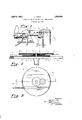
Fig. 1 is a fragmentary view of sound reproducing apparatus in connection with which my invention is adapted for use;
Fig. 2 is a side elevation of one embodiment of my invention; and
Fig. 3 is a view taken on the line 3-3 in Fig. 2.
My invention is adapted to be used with the turn table a of sound reproducing apparatus to produce differential speed with relation thereto and is adapted to carry a record which is engaged by the tone arm I; of such apparatus. The tone arm of apparatus of this character is pivotally mounted at a point such as 0 some distance away from the axis of rotation of the turn table and the weight of such arm is supported by a needle 6 in the head of the tone arm. The tone arm in operation preferably extends in operating position in substantially a horizontal plane when the needle I) rests upon the record d to be reproduced. To utilize the apparatus thus described without change, it is necessary, therefore, that any device placed upon the turn table to support the record be quite thin, so as not to disturb the relative angle of the tone arm. A pin a is arranged centrally of the turn table and is approximately one inch long and thus to permit the use of such pin to center my device and the record d carried thereby, it is necessary that my device be substantially less than three-fourths of an inch in overall thickness or height. Less thickness or height is desirable although not necessary.
My improved speed change device comprises two discs 0 and f arranged in stacked vertical alinement and the lowermost disc 6 is adapted to be arranged upon and carried by the upper surface of the turn table (1. Such surface is preferably and usually felt-covcred, so as to provide a resilient surface which has a relatively high coefficient of friction, so as to prevent relative slippage of the record of my device. Such disc 6 is preferably made of metal to secure strength and weight and the under surface e thereof is preferably roughened, such as being turned with a relatively coarse-edged tool to increase the relative coefficient friction between the under surface of the disc 6 and the surface of the turn 'table a. As has been noted heretofore, the turn table a is commonly provided with a centering pin a, which is in axial alinement with the center of rotation of the turn table, and it is over such centering pin that the record (I? to be reproduced is normally arranged.
Separating the discs e and f is a centrallyarranged upstanding tubular boss 9, which is secured to, and thus operates with, the disc 6. The said boss has a bore corresponding substantially to the diameter of the centering pin a over which it fits. J ournaled upon such boss and directly overlying the disc 6 is an intermediate member it free to rotate with respect to'both of such discs e and f. Overlying the member h and having free working clearance with regard thereto is a gear 21, which is'fixed to the boss g and thus rotates with the disc 6. An upstanding stud Z is carried by the intermediate member h at a point spaced from the center of rotation of said member and said stud carries two stacked gear elements Z and Z which are free to rotate upon said stud Z. The smaller of said gears Z meshes with the gear z and the larger one Z meshes with a gear is, which latter is fixed to the under surface of the upper disc f. The desired difference in rotatlon set out in the introduction to the specification is secured by proportioning said gears i, is, Z and Z with respect to each other. The member h is held against rotation by an extensible member m, which is adapted to be moved outwardly until it engages one of the stanchions or fixed members of the guard rail a, or some other convenient fixed member.
The disc 6 thus rotates with the turntable a, being in frictional engagement with such turntable. The gear 2' also rotates with the disc 6, being fixed thereto. The member h is held against rotation, and the disc f and thus the record d, rotate in the same direction as the turntable a, but at an increased rate. The gears are arranged so that when the turntable a rotates at 33 RQP. M., the disc f rotates at a speed of 7 8 R. P. M. The upper surface of the disc f carries a felt covering 0, which frictionally engages and protects the record d.
I claim:
1. In combination with the turn table and tone arm of sound reproducing apparatus, a relatively flat detachable speed change device comprising two relatively rotatable and axially alined discs, one resting in axially alinement upon and engaging the turn table, the other carrying in axial alinement and engaging the sound record to be engaged by the tone arm of such apparatus and means operatively connecting said two discs together and proportioned to produce predetermined differential rotation between the latter.
2. In combination with a turn table and tone arm of sound reproducing ap aratus, a relatively flat detachable speed c ange device comprising two relatively rotatable and axially alined discs, one resting in axially alinement upon and engagin the turn table, the other carrying in axial almement and engaging the sound record to be engaged by the .tone arm of such apparatus and a train of gears operatively connecting said two discs together and proportioned to produce predetermined differential rotation between the latter.
3. In combination with the turn table and tone arm of sound reproducing apparatus, a relatively flat detachable speed change device comprising two relatively rotatable and axially alined discs, one resting in axially alinement upon and engaging the turn table, the other carrying in axial alinement and engaging the sound record to be engaged by the tone arm of such apparatus, a member arranged intermediate said two discs provided with a locking device adapted for engaging a stationary portion of such apparatus thereby to fix said member against rotation and means in part carried by said member operatively connecting said two discs together and proportioned to produce predetermined differential rotation between the latter.
4. In combination with the turn table and tone arm of sound reproducing apparatus, a relatively flat detachable speed change device comprising two relatively rotatable and axially alined discs, one resting in axially alinement upon and engaging the turn table, the other carrying in axial alinement and engaging the sound record to be engaged by the tone arm of such apparatus, a member arranged intermediate said two discs provided with an extensible locking device adapted for engaging a stationary portion of such apparatus thereby to fix said member against rotation and means in part carried by said member operatively connecting said two discs together and proportioned to produce predetermined differential rotation between the latter.
5. A device for changing the effective speed of sound reproducing apparatus comprising two relatively rotatable discs mounted on a central axis, and means operatively connecting the two discs together and proportioned to produce predetermined differential rota tion between the latter.
6. A device for changing the effective speed of sound reproducing apparatus comprising two relatively rotatable discs mounted on a central axis, the pivotal connection between said two discs having an axial bore extending continuously thru the latter and means operatively connecting the two discs together and proportioned to produce predetermined differential rotation between the latter.
7. A device for changing the efl'ective speed of sound reproducing apparatus comprising two relatively rotatable discs mounted on a central axis, a member arranged intermediate said discs and means in part carried by said member operatively connecting the two discs together and proportioned to produce predetermined differential rotation between the latter.
signature.
8. A device for changing the effective speed of sound reproducing apparatus comprising two relatively rotatable discs mounted on a central axis, a member arranged intermediate said discs, the latter provided with a locking device for fixin said member against rotation and means in part carried by said member operatively connecting the two discs together and proportioned to produce predetermined difierential rotation between the latter.
9. A device for changing the effective speed of sound reproducing apparatus comprising two relatively rotatable discs mounted on a central axis, the pivotal connection between said two discs having an axial bore extending continuously thru the latter, a member arranged intermediate said discs, the latter provided with a locking device for fixing said member against rotation and means in part carried by said member operatively connecting the two discs together and proportioned to produce predetermined differential rotation between the latter. I
10. A device for changing the effective speed of sound reproducing apparatus comprising two relatively rotatable discs mounted on a central axis, a member arranged intermediate saiddiscs, the latter provided with an extensible locking device for fixing said member against rotation and means in part carried by said member operatively connecting the two discs together and proportioned to produce predetermined differential rotation between the latter.
In testimony whereof he has aflixed his LAWRENCE FRITZ.
Priority Applications (1)
| Application Number | Priority Date | Filing Date | Title |
|---|---|---|---|
| US451473A US1852456A (en) | 1930-05-10 | 1930-05-10 | Speed change device for sound reproducers |
Applications Claiming Priority (1)
| Application Number | Priority Date | Filing Date | Title |
|---|---|---|---|
| US451473A US1852456A (en) | 1930-05-10 | 1930-05-10 | Speed change device for sound reproducers |
Publications (1)
| Publication Number | Publication Date |
|---|---|
| US1852456A true US1852456A (en) | 1932-04-05 |
Family
ID=23792357
Family Applications (1)
| Application Number | Title | Priority Date | Filing Date |
|---|---|---|---|
| US451473A Expired - Lifetime US1852456A (en) | 1930-05-10 | 1930-05-10 | Speed change device for sound reproducers |
Country Status (1)
| Country | Link |
|---|---|
| US (1) | US1852456A (en) |
Cited By (7)
| Publication number | Priority date | Publication date | Assignee | Title |
|---|---|---|---|---|
| US2416583A (en) * | 1944-03-10 | 1947-02-25 | Arnold B Hartley | Record player |
| US2562665A (en) * | 1947-12-23 | 1951-07-31 | Daphne Invest Trust | Movement control device for magnetic sound heads on sound recording and sound reproducting machines |
| US2583954A (en) * | 1949-01-03 | 1952-01-29 | Kugler S Radio Service Inc | Turntable construction |
| US2598138A (en) * | 1949-04-14 | 1952-05-27 | John H Sharp | Phonograph change-speed mechanism |
| US2610258A (en) * | 1949-03-03 | 1952-09-09 | Columbia Broadcasting Syst Inc | Phonograph adaptor for long playing records |
| US2619840A (en) * | 1949-03-30 | 1952-12-02 | Theodore F Vaida | Talking machine |
| US2622882A (en) * | 1948-10-13 | 1952-12-23 | Elliott H Kahn | Disk type phonograph apparatus |
-
1930
- 1930-05-10 US US451473A patent/US1852456A/en not_active Expired - Lifetime
Cited By (7)
| Publication number | Priority date | Publication date | Assignee | Title |
|---|---|---|---|---|
| US2416583A (en) * | 1944-03-10 | 1947-02-25 | Arnold B Hartley | Record player |
| US2562665A (en) * | 1947-12-23 | 1951-07-31 | Daphne Invest Trust | Movement control device for magnetic sound heads on sound recording and sound reproducting machines |
| US2622882A (en) * | 1948-10-13 | 1952-12-23 | Elliott H Kahn | Disk type phonograph apparatus |
| US2583954A (en) * | 1949-01-03 | 1952-01-29 | Kugler S Radio Service Inc | Turntable construction |
| US2610258A (en) * | 1949-03-03 | 1952-09-09 | Columbia Broadcasting Syst Inc | Phonograph adaptor for long playing records |
| US2619840A (en) * | 1949-03-30 | 1952-12-02 | Theodore F Vaida | Talking machine |
| US2598138A (en) * | 1949-04-14 | 1952-05-27 | John H Sharp | Phonograph change-speed mechanism |
Similar Documents
| Publication | Publication Date | Title |
|---|---|---|
| US1852456A (en) | Speed change device for sound reproducers | |
| US2869877A (en) | Play-back sound reproducer | |
| US2478538A (en) | Sound translating device | |
| US2486661A (en) | Phonograph with moving stylus and stationary record | |
| US1930544A (en) | Sound reproducing device for moving pictures | |
| US2353370A (en) | Multiple-speed phonograph turntable | |
| US2486662A (en) | Phonograph with moving stylus and stationary record | |
| US2402150A (en) | Phonograph tone arm mounting | |
| US2335661A (en) | Double turntable | |
| US2446324A (en) | Recording and reproducing apparatus | |
| US2532293A (en) | Tone arm carriage | |
| US2173048A (en) | Portable sound recording and sound reproducing machine | |
| US1835240A (en) | Motion picture machine | |
| US1291515A (en) | Recording attachment. | |
| US2316175A (en) | Sound reproducing means | |
| US3124661A (en) | figure | |
| US2577649A (en) | Speed adjustment for phonograph turntables | |
| US2002111A (en) | System for synchronizing sound with motion pictures | |
| US2002854A (en) | Selective transmission fob motion | |
| US1768200A (en) | Sound-reproducing machine | |
| US3837738A (en) | Audio-visual apparatus including magnetic sheet mounting and hold-down means | |
| US1837243A (en) | Sound recording and reproducing system | |
| US1404870A (en) | Phonograph | |
| US697969A (en) | Phonograph or graphophone. | |
| US1342872A (en) | Device for forming grooves in sound-records |