US1852437A - Internal combustion engine driven vehicle with electric transmission - Google Patents
Internal combustion engine driven vehicle with electric transmission Download PDFInfo
- Publication number
- US1852437A US1852437A US427978A US42797830A US1852437A US 1852437 A US1852437 A US 1852437A US 427978 A US427978 A US 427978A US 42797830 A US42797830 A US 42797830A US 1852437 A US1852437 A US 1852437A
- Authority
- US
- United States
- Prior art keywords
- engine
- generator
- internal combustion
- combustion engine
- driven vehicle
- Prior art date
- Legal status (The legal status is an assumption and is not a legal conclusion. Google has not performed a legal analysis and makes no representation as to the accuracy of the status listed.)
- Expired - Lifetime
Links
- 238000002485 combustion reaction Methods 0.000 title description 6
- 230000005540 biological transmission Effects 0.000 title description 3
- 230000008878 coupling Effects 0.000 description 6
- 238000010168 coupling process Methods 0.000 description 6
- 238000005859 coupling reaction Methods 0.000 description 6
- 238000010276 construction Methods 0.000 description 5
- 241000501754 Astronotus ocellatus Species 0.000 description 2
- AAKRTZRMVMTCPV-UHFFFAOYSA-N 2-methoxy-6-propan-2-ylnaphthalene Chemical compound C1=C(C(C)C)C=CC2=CC(OC)=CC=C21 AAKRTZRMVMTCPV-UHFFFAOYSA-N 0.000 description 1
- 230000005484 gravity Effects 0.000 description 1
Images
Classifications
-
- F—MECHANICAL ENGINEERING; LIGHTING; HEATING; WEAPONS; BLASTING
- F02—COMBUSTION ENGINES; HOT-GAS OR COMBUSTION-PRODUCT ENGINE PLANTS
- F02B—INTERNAL-COMBUSTION PISTON ENGINES; COMBUSTION ENGINES IN GENERAL
- F02B63/00—Adaptations of engines for driving pumps, hand-held tools or electric generators; Portable combinations of engines with engine-driven devices
- F02B63/04—Adaptations of engines for driving pumps, hand-held tools or electric generators; Portable combinations of engines with engine-driven devices for electric generators
Definitions
- This invention relates to vehicles of the kind in which the power developed by an internal combustion engine is transmitted electrically through a generator coupled to the a; engine and has for its object to provide an improved connection between the engine and generator.
- the engine shaft is detachably but rigidly coupled to the generator shaft and the generator casing is connected at several points to the engine or itscasing in a manner which eliminates vibrations between these two separate units without entailing loss of accessibility to the bearings and the coupling of their adjacent shafts.
- the engine and generator casings are connected at three points to ensure a rigid structure, and these three points are so determined as to form an equilateral triangle, the shaft passing through the centre of gravity of the triangle and in a plane at right angles to its surface.
- the engine and generator may each be bolted to a common parallel sided frame and connected at a third point by directly engaging lugs on each unit or by means of some intermediate or interposed member.
- the engine and generator casings may be directly coupled at all three points as by bolts passing through forwardly projecting lugs at the adjacent end of each unit or by means of an intermediate member at one of these three points.
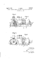
- Figure 2 is a cross-section. the lefthand side of the figure being taken on the line AA and the right on the line BB of Figure 1,
- Figure 3 is a side elevation of a modified construction and Figure 4 is a cross-section on the line CC of Figure 3.
- the engine and generator are each furnished with laterally projecting lugs 10 and 11 respectively by which these units are supported upon the parallel sides of a bed or frame 7.
- the engine casing is bolted to the frame by studs 8 and s milarly bolts or studs 9 are employed to hold the side ribs 12 of the generator casing 18 in place between the frame members 7.
- the adjacent ends of the engine shaft 4: and the generator shaft 5 are provided with integral flanges in the usual manner and these are connected by bolts 6 to form a rigid coupling.
- a third point of connection is provided between the engine casing and generator casing in the form of an intermediate member 16 which is rigidly screwed into a flange 18 on the engine casing and into a corresponding flange 17 on the generator casing. This arrangement prevents any vibrations which might take place in a horizontal plane at right angles to the axis of the shaft.
- the generator shaft 5 is rigidly but detachably connected to the engine shaft as in the previous construction, but the engine and generator casings are connected at the three po nts 21, 22 and 23, the generator casing being furnished with projecting lugs 24, 25. 26 cast in one with the end cover and preferably of channel section as shown in Figure 4, these lugs being connected by bolts 30 to similar lugs 2'7, 28 and 29 formed in one with the casing of the engine.
Landscapes
- Engineering & Computer Science (AREA)
- Chemical & Material Sciences (AREA)
- Combustion & Propulsion (AREA)
- Mechanical Engineering (AREA)
- General Engineering & Computer Science (AREA)
- Motor Or Generator Frames (AREA)
- Connection Of Motors, Electrical Generators, Mechanical Devices, And The Like (AREA)
Description
. April 5, 1932. Q S|MMEN 1,852,437
INTERNAL COMBUSTION ENGINE DRIVEN VEHICLE WITH ELECTRIC TRANSMISSION Filed Feb. 12, 1930 Patented Apr. 5, 1932 UNITED STATES PATENT OFFICE OSCAR SIMMEN, 0F ERLACH, SWITZERLAND, ASSIGNOR TO FIRM SULZER FREBES SOCIETE ANONYME, OF WINTERTIIUR, SWITZERLAND INTERNAL COMBUSTION ENGINE DRIVEN VEHICLE WITH ELECTRIC TRANSMISSION Application filed February 12, 1930, Serial No. 427,978, and in Switzerland. June 13, 1929,
This invention relates to vehicles of the kind in which the power developed by an internal combustion engine is transmitted electrically through a generator coupled to the a; engine and has for its object to provide an improved connection between the engine and generator.
According to this invention the engine shaft is detachably but rigidly coupled to the generator shaft and the generator casing is connected at several points to the engine or itscasing in a manner which eliminates vibrations between these two separate units without entailing loss of accessibility to the bearings and the coupling of their adjacent shafts.
Preferably the engine and generator casings are connected at three points to ensure a rigid structure, and these three points are so determined as to form an equilateral triangle, the shaft passing through the centre of gravity of the triangle and in a plane at right angles to its surface.
In practice the engine and generator may each be bolted to a common parallel sided frame and connected at a third point by directly engaging lugs on each unit or by means of some intermediate or interposed member. Alternatively the engine and generator casings may be directly coupled at all three points as by bolts passing through forwardly projecting lugs at the adjacent end of each unit or by means of an intermediate member at one of these three points.
Two constructional forms according to this invention are diagrammatically illustrated by way of example in the accompanying drawings in which Figure 1 is a side elevation,
Figure 2 is a cross-section. the lefthand side of the figure being taken on the line AA and the right on the line BB of Figure 1,
Figure 3 is a side elevation of a modified construction and Figure 4 is a cross-section on the line CC of Figure 3.
In the construction illustrated two cylinders 1 of a Diesel internal combustion engine are shown, the engine shaft 4 being connected by a flanged shaft coupling 3 to the shaft 5 of the generator 2.
In the construction shown in Figures 1 and 2, the engine and generator are each furnished with laterally projecting lugs 10 and 11 respectively by which these units are supported upon the parallel sides of a bed or frame 7. The engine casing is bolted to the frame by studs 8 and s milarly bolts or studs 9 are employed to hold the side ribs 12 of the generator casing 18 in place between the frame members 7.
The adjacent ends of the engine shaft 4: and the generator shaft 5 are provided with integral flanges in the usual manner and these are connected by bolts 6 to form a rigid coupling.
To prevent the two units vibrating and ad versely affecting the drive a third point of connection is provided between the engine casing and generator casing in the form of an intermediate member 16 which is rigidly screwed into a flange 18 on the engine casing and into a corresponding flange 17 on the generator casing. This arrangement prevents any vibrations which might take place in a horizontal plane at right angles to the axis of the shaft.
In the alternative construction shown in Figures 3 and 4 the generator shaft 5 is rigidly but detachably connected to the engine shaft as in the previous construction, but the engine and generator casings are connected at the three po nts 21, 22 and 23, the generator casing being furnished with projecting lugs 24, 25. 26 cast in one with the end cover and preferably of channel section as shown in Figure 4, these lugs being connected by bolts 30 to similar lugs 2'7, 28 and 29 formed in one with the casing of the engine.
It will be seen that the three points of connection 21, 22. 23 form the points of an equilateral triangle through the centre of which the coupled shafts 41, 5 pass so that vibrations in any direction are prevented.
I claim:
In an internal combustion engine in which the power is electrically transmitted by an electrical generator, a rigid but demountable coupling between the shafts of the engine and generator, a common horizontal frame for the engine and generator, these two latter being independently connected to and supported by said frame, a separate connection between said generator and said engine consisting of an independent rigid body demountably attached at one end to the gen erator cover and at the other end to the engine crank-case and lying above said shafts, said member taking all the vibration stresses ofi said coupling, said member being removable by hand to expose at least two-thirds of the periphery of the coupling.
In testimony whereof I have aflixed my OSCAR SIMMEN.
signature.
Applications Claiming Priority (1)
| Application Number | Priority Date | Filing Date | Title |
|---|---|---|---|
| CH1852437X | 1929-06-13 |
Publications (1)
| Publication Number | Publication Date |
|---|---|
| US1852437A true US1852437A (en) | 1932-04-05 |
Family
ID=4566513
Family Applications (1)
| Application Number | Title | Priority Date | Filing Date |
|---|---|---|---|
| US427978A Expired - Lifetime US1852437A (en) | 1929-06-13 | 1930-02-12 | Internal combustion engine driven vehicle with electric transmission |
Country Status (1)
| Country | Link |
|---|---|
| US (1) | US1852437A (en) |
-
1930
- 1930-02-12 US US427978A patent/US1852437A/en not_active Expired - Lifetime
Similar Documents
| Publication | Publication Date | Title |
|---|---|---|
| DE69803961T2 (en) | Drive device for hybrid vehicle | |
| US1852437A (en) | Internal combustion engine driven vehicle with electric transmission | |
| US3468389A (en) | Propulsion units for use with electric drive vehicles | |
| JPH01150026A (en) | Coupling device for crankshaft of internal combustion engine and driving shaft of auxiliary equipment | |
| US2793625A (en) | Engine frame | |
| US2019657A (en) | Internal combustion engine | |
| US2317849A (en) | Locomotive | |
| US2764143A (en) | Integral crankcase and gearcase assembly for an internal combustion engine | |
| US3429304A (en) | Engine accessory drive construction | |
| US2012778A (en) | Twin cylinder steam engine | |
| US1913199A (en) | Internal combustion engine | |
| GB336510A (en) | Improvements in or relating to internal combustion engine driven vehicles with electric transmission | |
| US2123005A (en) | Motor vehicle | |
| US1369668A (en) | Unitfh statf | |
| US1701366A (en) | Internal-combustion engine | |
| US2231260A (en) | Power unit mounting means | |
| US1120803A (en) | Engine. | |
| US884117A (en) | Motor-vehicle. | |
| US1529163A (en) | Combined steam and internal-combustion locomotive | |
| US1971998A (en) | Locomotive | |
| US1559601A (en) | Locomotive having combined internal-combustion and electric propulsion system | |
| US1502546A (en) | Combined steam and internal-combustion locomotive | |
| CN216866876U (en) | Flywheel housing assembly | |
| US2613613A (en) | Steam locomotive, including individual axle drives | |
| US2371011A (en) | Power plant |