US1852432A - Lighting fixture - Google Patents
Lighting fixture Download PDFInfo
- Publication number
- US1852432A US1852432A US201236A US20123627A US1852432A US 1852432 A US1852432 A US 1852432A US 201236 A US201236 A US 201236A US 20123627 A US20123627 A US 20123627A US 1852432 A US1852432 A US 1852432A
- Authority
- US
- United States
- Prior art keywords
- reflector
- globe
- holder
- neck
- flange
- Prior art date
- Legal status (The legal status is an assumption and is not a legal conclusion. Google has not performed a legal analysis and makes no representation as to the accuracy of the status listed.)
- Expired - Lifetime
Links
Images
Classifications
-
- F—MECHANICAL ENGINEERING; LIGHTING; HEATING; WEAPONS; BLASTING
- F21—LIGHTING
- F21V—FUNCTIONAL FEATURES OR DETAILS OF LIGHTING DEVICES OR SYSTEMS THEREOF; STRUCTURAL COMBINATIONS OF LIGHTING DEVICES WITH OTHER ARTICLES, NOT OTHERWISE PROVIDED FOR
- F21V17/00—Fastening of component parts of lighting devices, e.g. shades, globes, refractors, reflectors, filters, screens, grids or protective cages
- F21V17/10—Fastening of component parts of lighting devices, e.g. shades, globes, refractors, reflectors, filters, screens, grids or protective cages characterised by specific fastening means or way of fastening
- F21V17/12—Fastening of component parts of lighting devices, e.g. shades, globes, refractors, reflectors, filters, screens, grids or protective cages characterised by specific fastening means or way of fastening by screwing
-
- F—MECHANICAL ENGINEERING; LIGHTING; HEATING; WEAPONS; BLASTING
- F21—LIGHTING
- F21V—FUNCTIONAL FEATURES OR DETAILS OF LIGHTING DEVICES OR SYSTEMS THEREOF; STRUCTURAL COMBINATIONS OF LIGHTING DEVICES WITH OTHER ARTICLES, NOT OTHERWISE PROVIDED FOR
- F21V13/00—Producing particular characteristics or distribution of the light emitted by means of a combination of elements specified in two or more of main groups F21V1/00 - F21V11/00
- F21V13/02—Combinations of only two kinds of elements
- F21V13/04—Combinations of only two kinds of elements the elements being reflectors and refractors
-
- F—MECHANICAL ENGINEERING; LIGHTING; HEATING; WEAPONS; BLASTING
- F21—LIGHTING
- F21V—FUNCTIONAL FEATURES OR DETAILS OF LIGHTING DEVICES OR SYSTEMS THEREOF; STRUCTURAL COMBINATIONS OF LIGHTING DEVICES WITH OTHER ARTICLES, NOT OTHERWISE PROVIDED FOR
- F21V3/00—Globes; Bowls; Cover glasses
Definitions
- My invention relates to lighting fixtures and more particularly to an assembly of parts commonly known as a lighting globe, a re flector and a holder.
- One of the objects of my invention is to provide a holder and reflector adapted to embrace the neck of a lighting globe in such a manner as to cause the globe to support the reflector, the globe in turn being supported by the holder.
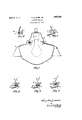
- Figure 1 is a sectional, schematic view of one form of my invention assembled.
- Figure 2 is an enlarged section of the globe neck reflector and holder shown in Figure 1 wherein the respective parts are about to be brought together in operative relationship.
- Figure 3 shows the elements of Figure 2 in operative relationship.
- Figure 4 shows a modified form of holder.
- Figure 5 shows a modified form of securing the parts of Figure 4 in operative relat1onshi 3.
- Figure 6 is a sectional view along the line 6-6 of Figure 5.
- 1 is a lighting globe having a neck portion as at 2 about the outside of which neck an annular channel 3 is formed.
- An annular flange 6 is provided about the opening 5 in the shade over which a bead 7 on holder 8 is adapted to fit when the parts are brought into operative relation.
- Screws 9 are adapted to project through threaded openings 10 and holder 8 and engage with the neck 2 of globe 1 to secure the assembly in operative relation.
- the reflector is adapted to rest adjacent with the opening 5 upon the globe 1 as at 11.
- Reflector 4 has projected through the neck portion 2 of globe 1 and rests upon the globe 59 as at 11.
- the holder 8 is brought down over FIXTURE 1927. Serial No. 201,236.
- JIn Figure 4 holder 8 is shown without'bead 7 being merely enlarged in inside diameter sufficiently to overlapor embrace bead 6 by a straight section in the holder 8.
- aglobe having a neck provided with a channel, the latter having a downwardly and inwardlydnclined wall, a reflector having an opening therein to receive the neck and being engaged with the globe and provided with a annular upwardly extending flange, a holder formed to engage about the neckand having its lower portion formed to engage with the flange of the reflector'and with the top of the latter soas to hold the reflector against the lobe, and screwsdisposed spaced above the ange of the reflector and extending through the lower portion of the holder and engageable with said inclined wall of the channel whereby upon inward turning of the screws same ride downwardly on said wall and thereby cause the holder to engage the flange of thereflector to center the latter and simultaneously force the reflectors against the e.
- a globe having a neck provided with a channel, the latter having a downwardly and inwardly inclined wall, a reflector having an openingthereinto receive the neck and being engaged with the globe and provided with an annular upwardly extending flange, a holder formed to engage about the neck and provided with a curved flange at its lower part, the free edge of which curved flangeengages with the flange of the reflector and with the top of the latter so as to hold the reflector against the globe, and screws disposed above the flange of the reflector and extending through the lower portion of the holder and engageable with said inclinedwall of the channel whereby upon inward turn ing of the screws same will ride downwardly on'said wall and thereby cause thecurved flange of the holder to engage the flange of the reflector and center the latter and simultaneously force the reflector against, the globe.
- a globe having a neck provided with a channel the latter having a downwardly and inwardly inclined wa-ll
- a reflector having an opening therein to receive the neck and being'engaged' with the globe and provided with an annular upfwardly extending flange
- a holder formed to engage about the neck and having its lower portion formed to engage with the flange of the reflector and with the top ofthe latter so as to hold the reflector against the globe
- a globe having a neck provided with a channel, the latter having a downwardly and inwardly inclined wall, a reflector having an opening therein to receive the neck and being engaged with the globe and provided with an annular upwardly extending flange, a holder termed to engage about the neck and pr ovid d with e, curved flange at its lower part the free'edge ofwhich curved flange is adapted to ena'g the flange of the reflector and the top Q the latterjso as to 'hold the reflector aga nst the globe, and means'carried the holder and disposed above'the flange of the refleQ Qi aiid engageable with saidincl ined wallet the channel so as to ride'downwardly thereen, and cause the curved flange of the heldr t9 en gage the flange ofthe reflector to center the latter andto simultanenously. force the' lef flectol, against
Description
April 5, JR 1,852,432
LIGHTING FIXTURE Filed June 24, 1927 26 0221,; INVENTOR XLZZUW ATTORNY.
Patented Apr. 5, 1932 UNITED STATES PATENT OFFICE LIGHTING Application filed June 24,
My invention relates to lighting fixtures and more particularly to an assembly of parts commonly known as a lighting globe, a re flector and a holder.
One of the objects of my invention is to provide a holder and reflector adapted to embrace the neck of a lighting globe in such a manner as to cause the globe to support the reflector, the globe in turn being supported by the holder.
The invention will be readily understood from the following specification together with the accompanying drawings in which like references refer to similar elements in the respective figures.
Figure 1 is a sectional, schematic view of one form of my invention assembled.
Figure 2 is an enlarged section of the globe neck reflector and holder shown in Figure 1 wherein the respective parts are about to be brought together in operative relationship.
Figure 3 shows the elements of Figure 2 in operative relationship.
Figure 4 shows a modified form of holder.
Figure 5 shows a modified form of securing the parts of Figure 4 in operative relat1onshi 3.
Figure 6 is a sectional view along the line 6-6 of Figure 5.
Referring particularly to Figure 1, 1 is a lighting globe having a neck portion as at 2 about the outside of which neck an annular channel 3 is formed.
4 is a shade having an opening 5 adapted to receive the neck portion of the globe.
An annular flange 6 is provided about the opening 5 in the shade over which a bead 7 on holder 8 is adapted to fit when the parts are brought into operative relation.
The reflector is adapted to rest adjacent with the opening 5 upon the globe 1 as at 11.
The assembly and operation is as follows Reflector 4 has projected through the neck portion 2 of globe 1 and rests upon the globe 59 as at 11. The holder 8 is brought down over FIXTURE 1927. Serial No. 201,236.
the neck 2 of globe 1 projecting through the opening in the reflector. Screws 9 are inserted in threaded openings 10 and bolder and projected therethrough until they engage with the upper portion of annular ring about the neck of the globe. It will be readily noted that as screws 9 are turned up, they will draw the holder 8 down towards the reflector 4 and cause the bead 7 on the holder to embrace or slip over flange 6 of the reflector and as the screws 9 are projected further into the annular ring 3, the relative telescopic movement between holder 8 and the neck of globe 1 continues until screws 9 have found the deepest part of annular ring or channel 3 or until the holder 8 is brought snugly and securely down on the reflector pressing the latter against the globe 1. Of course it is obvious that the relation of the parts will be such that reflector 4 will be fitted on globe 1, flange 6 of the reflector being embraced by bead 7 on holder 8 before the screws 9 find the deepest part of the annular channel 3.
Referring to Figure 2, it will be noted that screw 9 is engaging with the upper portion of annular channel 3 about the neck of the globe 1 and that head 7 of holder8 has not yet engaged with or embraced flange 6 of reflector 4 whereas in Figure 3 the full line position of the respective elements shows the parts in operative position. 3
JIn Figure 4 holder 8 is shown without'bead 7 being merely enlarged in inside diameter sufficiently to overlapor embrace bead 6 by a straight section in the holder 8.
It will be fully obvious to those skilled in the art that other means than threaded means 9 may be used to engage the neck of holder 1 to secure the parts in operative relationship and as shown in Figures 5 and 6 an opening 12 in holder 8 through which a spring clip 13 is provided in which the operation consists of pulling the spring clip 13 outwardly through opening 12 in holder 8 as indicated at 13A in Figure 6 as the holder is brought down over the neck 2 of the globe. Clips 13 are then released and as they seek to find their normal position as shown in the full lines of Figures 5 and 6, they engage with the upper portion of the channel 3 about the neck of the globe and force the parts together and secure them in operative relationship.
It will be noted that a minimum number of parts are necessary in this novel structure and hat screws 9 or clips 13 do not project through or engage with reflector 4: at all.
Other modifications of parts embodying my invention will be readily apparent to those skilled in the art and I claim as my invention all such modifications as follows within the scope of the following claims What I claim is:
1. In a lighting fixture, aglobe having a neck provided with a channel, the latter having a downwardly and inwardlydnclined wall, a reflector having an opening therein to receive the neck and being engaged with the globe and provided with a annular upwardly extending flange, a holder formed to engage about the neckand having its lower portion formed to engage with the flange of the reflector'and with the top of the latter soas to hold the reflector against the lobe, and screwsdisposed spaced above the ange of the reflector and extending through the lower portion of the holder and engageable with said inclined wall of the channel whereby upon inward turning of the screws same ride downwardly on said wall and thereby cause the holder to engage the flange of thereflector to center the latter and simultaneously force the reflectors against the e. i a 2. In a lighting fixture, a globe having a neck provided with a channel, the latter having a downwardly and inwardly inclined wall, a reflector having an openingthereinto receive the neck and being engaged with the globe and provided with an annular upwardly extending flange, a holder formed to engage about the neck and provided with a curved flange at its lower part, the free edge of which curved flangeengages with the flange of the reflector and with the top of the latter so as to hold the reflector against the globe, and screws disposed above the flange of the reflector and extending through the lower portion of the holder and engageable with said inclinedwall of the channel whereby upon inward turn ing of the screws same will ride downwardly on'said wall and thereby cause thecurved flange of the holder to engage the flange of the reflector and center the latter and simultaneously force the reflector against, the globe. v
3. In alighting fixture, a globe having a neck provided with a channel the latter having a downwardly and inwardly inclined wa-ll,'a reflector having an opening therein to receive the neck and being'engaged' with the globe and provided with an annular upfwardly extending flange, a holder formed to engage about the neck and having its lower portion formed to engage with the flange of the reflector and with the top ofthe latter so as to hold the reflector against the globe, and means carried by the holder and disposed above the flange of the reflector and engageable with said inclined wall of the channel so as to ride downwardly thereon and cause the holder to engage the flange of the reflector to ent r h latter nd to s multane y force the reflector against the top of the globe. Y 4. In a lighting fixture, a globe having a neck provided with a channel, the latter having a downwardly and inwardly inclined wall, a reflector having an opening therein to receive the neck and being engaged with the globe and provided with an annular upwardly extending flange, a holder termed to engage about the neck and pr ovid d with e, curved flange at its lower part the free'edge ofwhich curved flange is adapted to ena'g the flange of the reflector and the top Q the latterjso as to 'hold the reflector aga nst the globe, and means'carried the holder and disposed above'the flange of the refleQ Qi aiid engageable with saidincl ined wallet the channel so as to ride'downwardly thereen, and cause the curved flange of the heldr t9 en gage the flange ofthe reflector to center the latter andto simultanenously. force the' lef flectol, against the top or the globe. In testimony whereof I signature; ENB L
Priority Applications (1)
| Application Number | Priority Date | Filing Date | Title |
|---|---|---|---|
| US201236A US1852432A (en) | 1927-06-24 | 1927-06-24 | Lighting fixture |
Applications Claiming Priority (1)
| Application Number | Priority Date | Filing Date | Title |
|---|---|---|---|
| US201236A US1852432A (en) | 1927-06-24 | 1927-06-24 | Lighting fixture |
Publications (1)
| Publication Number | Publication Date |
|---|---|
| US1852432A true US1852432A (en) | 1932-04-05 |
Family
ID=22745036
Family Applications (1)
| Application Number | Title | Priority Date | Filing Date |
|---|---|---|---|
| US201236A Expired - Lifetime US1852432A (en) | 1927-06-24 | 1927-06-24 | Lighting fixture |
Country Status (1)
| Country | Link |
|---|---|
| US (1) | US1852432A (en) |
Cited By (1)
| Publication number | Priority date | Publication date | Assignee | Title |
|---|---|---|---|---|
| WO2000001985A1 (en) * | 1998-07-02 | 2000-01-13 | Jari Ruuttu | Light fitting |
-
1927
- 1927-06-24 US US201236A patent/US1852432A/en not_active Expired - Lifetime
Cited By (2)
| Publication number | Priority date | Publication date | Assignee | Title |
|---|---|---|---|---|
| WO2000001985A1 (en) * | 1998-07-02 | 2000-01-13 | Jari Ruuttu | Light fitting |
| US6474831B1 (en) | 1998-07-02 | 2002-11-05 | Jari Ruuttu | Light fitting |
Similar Documents
| Publication | Publication Date | Title |
|---|---|---|
| US1852432A (en) | Lighting fixture | |
| US2731547A (en) | Lamp assembly | |
| US1151377A (en) | Light unit. | |
| US1696875A (en) | Clinch collar for shades | |
| US1587330A (en) | Stud fastening | |
| US2240659A (en) | Holder for reflectors and the like | |
| US2264951A (en) | Lighting fixture | |
| US1753374A (en) | Bowl-holding means for lighting fixtures | |
| US1291510A (en) | Lamp-shade. | |
| US1426951A (en) | Shade holder for threaded electric-lamp sockets | |
| US1538830A (en) | Spring shade holder | |
| US803883A (en) | Incandescent-lamp-shade holder. | |
| US940530A (en) | Lamp-globe. | |
| US1018241A (en) | Shade-holder. | |
| US2916611A (en) | Direct lighting fixtures | |
| US1704024A (en) | Shade holder | |
| US2247771A (en) | Bridge lamp and a diffusing bowl therefor | |
| US1530975A (en) | Lamp fixture | |
| US1605696A (en) | Shade holder for electric-light fixtures | |
| US1235632A (en) | Upright shade-holder. | |
| US1693232A (en) | Screwless holder for lighting fixtures | |
| US1608485A (en) | Holder for domes, globes, and like objects | |
| US2129335A (en) | Electric light fixture | |
| US964519A (en) | Shade-holder. | |
| US1505394A (en) | Shade or globe supporting means |