US1852431A - Dam - Google Patents
Dam Download PDFInfo
- Publication number
- US1852431A US1852431A US409489A US40948929A US1852431A US 1852431 A US1852431 A US 1852431A US 409489 A US409489 A US 409489A US 40948929 A US40948929 A US 40948929A US 1852431 A US1852431 A US 1852431A
- Authority
- US
- United States
- Prior art keywords
- arch
- buttress
- wing wall
- dam
- thrust
- Prior art date
- Legal status (The legal status is an assumption and is not a legal conclusion. Google has not performed a legal analysis and makes no representation as to the accuracy of the status listed.)
- Expired - Lifetime
Links
- 230000005484 gravity Effects 0.000 description 14
- 230000001154 acute effect Effects 0.000 description 9
- 238000010276 construction Methods 0.000 description 9
- 101150097977 arch-1 gene Proteins 0.000 description 8
- 238000011144 upstream manufacturing Methods 0.000 description 4
- 239000000463 material Substances 0.000 description 3
- XLYOFNOQVPJJNP-UHFFFAOYSA-N water Substances O XLYOFNOQVPJJNP-UHFFFAOYSA-N 0.000 description 3
- 230000007423 decrease Effects 0.000 description 2
- 229910001294 Reinforcing steel Inorganic materials 0.000 description 1
- 229910052729 chemical element Inorganic materials 0.000 description 1
- 230000003247 decreasing effect Effects 0.000 description 1
- 230000003014 reinforcing effect Effects 0.000 description 1
- 239000011435 rock Substances 0.000 description 1
- 238000012876 topography Methods 0.000 description 1
Images
Classifications
-
- E—FIXED CONSTRUCTIONS
- E02—HYDRAULIC ENGINEERING; FOUNDATIONS; SOIL SHIFTING
- E02B—HYDRAULIC ENGINEERING
- E02B7/00—Barrages or weirs; Layout, construction, methods of, or devices for, making same
- E02B7/02—Fixed barrages
- E02B7/04—Dams across valleys
- E02B7/08—Wall dams
- E02B7/12—Arch dams
Definitions
- This invention relates to the construction of concrete dams and the primary object of the invention is to provide a dam of this type which will be less expensive and which can be built in a shorter period of time than dams such as heretofore constructed.
- An object of the invention is to provide a dam of novel construction which is a combination of an arch dam with a forked abutment. This feature has been recognized in my co-pending application, Serial No. 319,- 205, filed, November 14, 1928, over which the construction disclosed in this application may be considered as an improvement.
- Another object of my invention is to provide a dam having its central portion of arch construction and one or both sides or wings of gravity section construction, and having buttresses which cooperate with the wings of the dam in sustaining the thrust of the arched portion of the dam.
- the combination is highly advantageous in that the buttresses do not alone have to sustain the thrust of the arch but instead the portions of the dam which are of gravity section assist in weighting down the ends of the arch and in sustaining the thrust.
- the arch abutments comprising buttresses and gravity wing walls permit to make the arch of the dam shorter and also permit the use of shorter arch radii and smaller thicknesses of the arch in the highest portion of the dam.
- the abutments are of forked shape and offer large areas in shear and upon the foundation material for resisting the thrust of the arch.
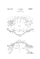
- Figure 1 is a schematic plan view of the dam embodying the invention.
- Figure 2 is a view in elevation of the dam shown in Figure 1.
- Figure 3 is a horizontal section through a portion of the dam shown in Figures 1 and 2 and may be considered as having been taken along the line 3--3 of Figure 2.
- Figure 4 is a horizontal section through the I
- the buttress 8 and wing wall4 form together a forked abutment 2which is especially well adapted to support the thrust of the arch 1.
- WVhile I have shown the arch 1 to be supported at each end by a forked abutment 2, it is understood that in certain cases one end of the arch may abut directly against the rock of the canyon walls or upon another structure. In such a case only one forked abutment 2 may be required for the arch 1.
- the buttress 3 and the adjacent wing wall 4 form an acute angle with each other and they are so arranged that the direction D of the arch thrust forms an acute angle a; with the direction of the buttress 3, and forms another acute angle 6 with the direction of the wing wall 4, such as shown in Figure 1.
- I may construct the gravity wing wall 4 with its full cross-section at its junction with the arch 1 such that the portion 7 of the wall 4 extends beyond the buttress 3 on the downhill side.
- the base of the portion 7 extends beyond the base of the buttress 3 and is of *value in supporting the water pressure acting upon the upstream face of the wall 4.
- I may construct the dam such that the buttress 3 extends substantially in the direction of the total thrust E of the upper portion of the arch 1.
- the buttress 3 will have to carry most, if not all of the arch thrust E.
- the gravity wing wall 4 may thenbe disposed at an acute angle 2' with the direction of the arch thrust and towards the side of the reservoir. According to the size of the angle 71 a smaller or larger proportion of the arch thrust will be thrown upon the wall 4 and this one may be built in a direction which takes the best advantage of the topography of the dam site.
- the thrust of the arch is carried by a wing wall 'of gravity section, whereby this wing wall extends in the direction of the tangent to the arch at its junction with the wing wall.
- gravity tangents must often be rather long in order to fit properly into the hillside.
- the gravity wing wall 4 extends at an angle with the tangent to the arch, as shown in Figs. 1 and 3, and this angle may be chosen within wide limits so as to best suit the topographic conditions of any site, inasmuch as the buttress 3 helps the support the arch thrust.
- the arch 1 of the dam may have an upstream face of constant radius of curvature
- orit maybe of the variable radius arch type .in which the arch radius decreases from the .crest towards the baseof the. arch.
- upper arch element 8 at its junction with the wingwall 4 forms a certain angle 0 with the up-stream face of the wing wall 4, and the tangent to the up-stream face of a lower arch element 9 forms a smaller angle (Z with the up-stream face of the wing wall 4.
- the tangents to the intrados of the arch elements form angles 6 and f with the inner face of the buttress 3, which angles decrease in size from the base of the buttress 3 upwards towards the crest, so that angle 6 is smaller than angle I
- angle I For relatively thin arch elements like.
- a concrete dam comprising an arch subjected to water pressure, and means for carryingthe thrust of the upper portion of said arch, comprising a buttress and a wing wall',the direction of the thrust of said arch at the junction of the arch with the buttress I forming an acute angle with thedirection of the buttress and forming anotheracute angle with the direction of said wing. wall, the base of the buttress extending downstream beyond the base of said wing wall.
- a concrete dam comprising an arch, an abutment for resist ng the thrust of the upper portion of said arch,sa1d abutment comprising a buttress wall extending substantiah abutment comprising a gravity wing wall disposed laterally relative to said arch elemerits, the tangent to the up-stream face of the upper arch element at the junction with the wing wall forming an angle with the upstream face of the wing wall, the tangent to the upstream face of the lower arch element forming asmaller angle with the Lip-stream face of said wing wall.
- a concrete dam construction comprising superposed arch elements, and means for carrying the thrusts of said arch elements comprising a buttress and a wing wall of gravity section, one upper of said arch elements being located near the crest of said dam, and one lower arch element being located a certain distance below the crest oi": the dam, the directions of the thrusts of said arch elements at the spring lines forming angles with the direction of said buttress, said angle between the direction of the thrust of the upper arch element with the direction of the buttress being larger than the angle between the direction of the thrust of the lower arch element with the direction of said buttress.
- a concrete dam construction comprising superposed arch elements of different thickness and different radii of curvature, means for carrying the thrust of said arch elements comprising a buttress and a wing wall, the directions of the thrusts of said arch elements at the spring lines forming angles with the direction of said buttress, said angles being larger for said arch elements located near the crest of the dam than for said arch ele ments located a certain distance below the crest.
- a concrete dam comprising superposed arch elements of difierent radii of curvature, means for carrying the thrust of said arch elements comprising a buttress and a wing wall, the directions of the thrusts of said arch elements forming angles with the direction of said wing wall, said angles being smaller for said arch elements located near the crest of the dam than for said arch elements located a certain distance below the crest.
- a concrete dam construction comprising superposed arch elements, means for carrying the thrust of said arch elements comprising a buttress and a wing wall disposed at an acute angle with each other, the base of the buttress extending down-stream beyond the base of said wing wall, and reinforcing steel bars extending between said buttress and said wing wall and cross-wise to the direction of said thrust tending to promote monolithic action between said arch, said buttress and said wing wall.
- a concrete dam construction comprising an arched portion and means for carrying the thrust of the upper part of said arched portion including a buttress and a wing wall of gravity section disposed at an angle with each other such that the base of said Wing wall extends beyond the area of the base of said buttress towards the downhill side sub stantially as described.
Landscapes
- Engineering & Computer Science (AREA)
- Structural Engineering (AREA)
- General Engineering & Computer Science (AREA)
- Mechanical Engineering (AREA)
- Civil Engineering (AREA)
- Bridges Or Land Bridges (AREA)
Description
April 5, 3 F. A. NOETZLI DAM Filed Nov. 25, 192
INVEHTOR JZdMl/Kalz) Patented Apr. 5, 1932 FRED A. NOETZLI, 013 LOS ANGELES, CALIFORNIA DAM Application filed November 25, 1929. Serial No. 409,489.
This invention relates to the construction of concrete dams and the primary object of the invention is to provide a dam of this type which will be less expensive and which can be built in a shorter period of time than dams such as heretofore constructed.
An object of the invention is to provide a dam of novel construction which is a combination of an arch dam with a forked abutment. This feature has been recognized in my co-pending application, Serial No. 319,- 205, filed, November 14, 1928, over which the construction disclosed in this application may be considered as an improvement.
Another object of my invention is to provide a dam having its central portion of arch construction and one or both sides or wings of gravity section construction, and having buttresses which cooperate with the wings of the dam in sustaining the thrust of the arched portion of the dam. The combination is highly advantageous in that the buttresses do not alone have to sustain the thrust of the arch but instead the portions of the dam which are of gravity section assist in weighting down the ends of the arch and in sustaining the thrust. The arch abutments comprising buttresses and gravity wing walls permit to make the arch of the dam shorter and also permit the use of shorter arch radii and smaller thicknesses of the arch in the highest portion of the dam. The abutments are of forked shape and offer large areas in shear and upon the foundation material for resisting the thrust of the arch.
With the foregoing and other objects in view which will be made manifest in the following detailed description and specifically pointed out in the appended claims, reference is had to the accompanying drawings for an illustrative embodiment of the invention, wherein:
Figure 1 is a schematic plan view of the dam embodying the invention.
Figure 2 is a view in elevation of the dam shown in Figure 1.
Figure 3 is a horizontal section through a portion of the dam shown in Figures 1 and 2 and may be considered as having been taken along the line 3--3 of Figure 2.
Figure 4 is a horizontal section through the I The buttress 8 and wing wall4 form together a forked abutment 2which is especially well adapted to support the thrust of the arch 1. WVhile I have shown the arch 1 to be supported at each end by a forked abutment 2, it is understood that in certain cases one end of the arch may abut directly against the rock of the canyon walls or upon another structure. In such a case only one forked abutment 2 may be required for the arch 1. The buttress 3 and the adjacent wing wall 4 form an acute angle with each other and they are so arranged that the direction D of the arch thrust forms an acute angle a; with the direction of the buttress 3, and forms another acute angle 6 with the direction of the wing wall 4, such as shown in Figure 1. By
arranging the buttress 3 and the wing wall 4 at an acute angle with each other, these two structural members which together form the abutment 2 of the arch 1 are intimately connected with each other, and their foundation areas, as well as certain parts of these members themselves, overlap andare combined so that certain parts of the concrete are stressed in the direction of the buttress 3 and the wing wall 4, and at the same time help to support a part of the water pressure by gravity action in the wing wall 4. The thrust of the arch 1 is carried by the combined action of buttress 3 and wing wall 4, that is, by the abutment 2. It is therefore of importance that the buttress 3 and the wing wall 4 act properly together, and to improve and safeguard such monolithic action, I may place reinforcing bars 5 in the abutment 2 crosswise to the direction of the arch thrust, these bars 5 to extend from the buttress 3 into the wing wall 4, as shown in Figure 1. I may also add a body 6 of concrete material between the buttress 3 and the wing wall 4 as shown in Figures 1 and 4 to avoid re-entrant angles between buttress and wing wall, and thereby strengthen the abutment 2. Of course, the'body 6 of concrete is built integrally and monolithically with the buttress 3 and the wing wall-4, and
1 such as shown in Figure 1. In such a case,
I may construct the gravity wing wall 4 with its full cross-section at its junction with the arch 1 such that the portion 7 of the wall 4 extends beyond the buttress 3 on the downhill side. Thus, the base of the portion 7 extends beyond the base of the buttress 3 and is of *value in supporting the water pressure acting upon the upstream face of the wall 4.
I may construct the dam such that the buttress 3 extends substantially in the direction of the total thrust E of the upper portion of the arch 1. Thus, the buttress 3 will have to carry most, if not all of the arch thrust E. The gravity wing wall 4 may thenbe disposed at an acute angle 2' with the direction of the arch thrust and towards the side of the reservoir. According to the size of the angle 71 a smaller or larger proportion of the arch thrust will be thrown upon the wall 4 and this one may be built in a direction which takes the best advantage of the topography of the dam site.
In some arch dams built heretofore the thrust of the arch is carried by a wing wall 'of gravity section, whereby this wing wall extends in the direction of the tangent to the arch at its junction with the wing wall. Theseso-called gravity tangents must often be rather long in order to fit properly into the hillside. In my improved dam the gravity wing wall 4 extends at an angle with the tangent to the arch, as shown in Figs. 1 and 3, and this angle may be chosen within wide limits so as to best suit the topographic conditions of any site, inasmuch as the buttress 3 helps the support the arch thrust.
The arch 1 of the dam may have an upstream face of constant radius of curvature,
orit maybe of the variable radius arch type .in which the arch radius decreases from the .crest towards the baseof the. arch. The
"upper arch element 8 at its junction with the wingwall 4 forms a certain angle 0 with the up-stream face of the wing wall 4, and the tangent to the up-stream face of a lower arch element 9 forms a smaller angle (Z with the up-stream face of the wing wall 4. On the other hand, the tangents to the intrados of the arch elements form angles 6 and f with the inner face of the buttress 3, which angles decrease in size from the base of the buttress 3 upwards towards the crest, so that angle 6 is smaller than angle I For relatively thin arch elements like.
those at or near the crest of arch dams the of the buttress 3 than theangle h which the direction of the arch thrust F in the lower element 9 forms with the direction of the buttress 3. The angle iwhich the arch thrust E of the upper element 8 forms with thediw rection of the wing wall 4 is smaller than the angle 3' between the direction of the arch thrust F of the lower element 9 andthe di rection of the wing wall 4. I claim:
1. A concrete dam comprising an arch subjected to water pressure, and means for carryingthe thrust of the upper portion of said arch, comprising a buttress and a wing wall',the direction of the thrust of said arch at the junction of the arch with the buttress I forming an acute angle with thedirection of the buttress and forming anotheracute angle with the direction of said wing. wall, the base of the buttress extending downstream beyond the base of said wing wall.
2. A concrete dam comprising an arch, an abutment for resist ng the thrust of the upper portion of said arch,sa1d abutment comprising a buttress wall extending substantiah abutment comprising a gravity wing wall disposed laterally relative to said arch elemerits, the tangent to the up-stream face of the upper arch element at the junction with the wing wall forming an angle with the upstream face of the wing wall, the tangent to the upstream face of the lower arch element forming asmaller angle with the Lip-stream face of said wing wall.
a. In a concrete dam the combination of a series of arch elements with an abutment comprising a buttress and a gravity wing wall, the tangents to the intrados of said arch elements forming angles with the inner face of said buttress, said angles decreasing in size from the base of said buttress upwards.
5. A concrete dam construction comprising superposed arch elements, and means for carrying the thrusts of said arch elements comprising a buttress and a wing wall of gravity section, one upper of said arch elements being located near the crest of said dam, and one lower arch element being located a certain distance below the crest oi": the dam, the directions of the thrusts of said arch elements at the spring lines forming angles with the direction of said buttress, said angle between the direction of the thrust of the upper arch element with the direction of the buttress being larger than the angle between the direction of the thrust of the lower arch element with the direction of said buttress.
6. A concrete dam construction comprising superposed arch elements of different thickness and different radii of curvature, means for carrying the thrust of said arch elements comprising a buttress and a wing wall, the directions of the thrusts of said arch elements at the spring lines forming angles with the direction of said buttress, said angles being larger for said arch elements located near the crest of the dam than for said arch ele ments located a certain distance below the crest.
7. A concrete dam comprising superposed arch elements of difierent radii of curvature, means for carrying the thrust of said arch elements comprising a buttress and a wing wall, the directions of the thrusts of said arch elements forming angles with the direction of said wing wall, said angles being smaller for said arch elements located near the crest of the dam than for said arch elements located a certain distance below the crest.
8. In a concrete dam the combination of an arch with an abutment comprising a buttress and a gravity wing wall being disposed at an acute angle with each other the slope of the down-stream face of said buttress being flatter than the slope of the downstream face of said wing wall, and material added to and between said buttress and said wing wall tending to promote improved combined action of said buttress and said wing wall for supporting the thrust of said arch.
9. A concrete dam construction comprising superposed arch elements, means for carrying the thrust of said arch elements comprising a buttress and a wing wall disposed at an acute angle with each other, the base of the buttress extending down-stream beyond the base of said wing wall, and reinforcing steel bars extending between said buttress and said wing wall and cross-wise to the direction of said thrust tending to promote monolithic action between said arch, said buttress and said wing wall.
10. A concrete dam construction comprising an arched portion and means for carrying the thrust of the upper part of said arched portion including a buttress and a wing wall of gravity section disposed at an angle with each other such that the base of said Wing wall extends beyond the area of the base of said buttress towards the downhill side sub stantially as described.
11. In a dam the combination of an arch with a buttress and a wing wall arranged at an acute angle with each other and in such a a position relative to each other that the thrust of a certain portion of said arch is supported in part by the buttress and in part by the wing wall, the slope of the rear face of said buttress being flatter than the downstream slope of said wing Wall, andmeans interposed between said buttress and said wing wall tending to improve their ability to support said thrust.
FRED A. NOE'IZLI.
Priority Applications (1)
| Application Number | Priority Date | Filing Date | Title |
|---|---|---|---|
| US409489A US1852431A (en) | 1929-11-25 | 1929-11-25 | Dam |
Applications Claiming Priority (1)
| Application Number | Priority Date | Filing Date | Title |
|---|---|---|---|
| US409489A US1852431A (en) | 1929-11-25 | 1929-11-25 | Dam |
Publications (1)
| Publication Number | Publication Date |
|---|---|
| US1852431A true US1852431A (en) | 1932-04-05 |
Family
ID=23620704
Family Applications (1)
| Application Number | Title | Priority Date | Filing Date |
|---|---|---|---|
| US409489A Expired - Lifetime US1852431A (en) | 1929-11-25 | 1929-11-25 | Dam |
Country Status (1)
| Country | Link |
|---|---|
| US (1) | US1852431A (en) |
Cited By (1)
| Publication number | Priority date | Publication date | Assignee | Title |
|---|---|---|---|---|
| RU2576444C1 (en) * | 2014-09-01 | 2016-03-10 | Евгений Николаевич Хрусталёв | En khrustalev method of preventing accident risk of hydraulic power plant and device for its implementation |
-
1929
- 1929-11-25 US US409489A patent/US1852431A/en not_active Expired - Lifetime
Cited By (1)
| Publication number | Priority date | Publication date | Assignee | Title |
|---|---|---|---|---|
| RU2576444C1 (en) * | 2014-09-01 | 2016-03-10 | Евгений Николаевич Хрусталёв | En khrustalev method of preventing accident risk of hydraulic power plant and device for its implementation |
Similar Documents
| Publication | Publication Date | Title |
|---|---|---|
| US2094167A (en) | Revetment | |
| US1947151A (en) | Sheet-metal-piling wall structure | |
| US2138037A (en) | Earth retainer | |
| US3570253A (en) | Constructional works | |
| US1852431A (en) | Dam | |
| US786059A (en) | Subway structure. | |
| US1422821A (en) | Sheet-piling wall construction | |
| US3282056A (en) | Flexible retaining wall structure | |
| US2666296A (en) | Dam | |
| US1808904A (en) | Dam and method of constructing the same | |
| US2017899A (en) | Building structure | |
| US1797517A (en) | Dam construction | |
| US1860590A (en) | Method of constructing dams | |
| US1736939A (en) | Open-structure dam | |
| SU896165A1 (en) | Dam made of locally available materials | |
| US1672102A (en) | Wharf or pier | |
| US1047501A (en) | Dam. | |
| US1807358A (en) | Dam construction | |
| US1860589A (en) | Dam construction | |
| US1846840A (en) | Dam | |
| US1681427A (en) | noetzli | |
| US1885057A (en) | Dam | |
| USRE18104E (en) | Extern all y-reenforced construction | |
| US2407952A (en) | Dam structure | |
| RU82715U1 (en) | WATER GRAIN STRUCTURE UNDER THE BULK |