US1852430A - Freight car ladder - Google Patents
Freight car ladder Download PDFInfo
- Publication number
- US1852430A US1852430A US514494A US51449431A US1852430A US 1852430 A US1852430 A US 1852430A US 514494 A US514494 A US 514494A US 51449431 A US51449431 A US 51449431A US 1852430 A US1852430 A US 1852430A
- Authority
- US
- United States
- Prior art keywords
- section
- ladder
- wall
- shaft
- movable
- Prior art date
- Legal status (The legal status is an assumption and is not a legal conclusion. Google has not performed a legal analysis and makes no representation as to the accuracy of the status listed.)
- Expired - Lifetime
Links
- 238000010276 construction Methods 0.000 description 5
- 230000005484 gravity Effects 0.000 description 3
- 230000004048 modification Effects 0.000 description 2
- 238000012986 modification Methods 0.000 description 2
- 230000009194 climbing Effects 0.000 description 1
- 238000009434 installation Methods 0.000 description 1
- 238000004519 manufacturing process Methods 0.000 description 1
- 238000000034 method Methods 0.000 description 1
- 238000003825 pressing Methods 0.000 description 1
Images

Classifications
-
- B—PERFORMING OPERATIONS; TRANSPORTING
- B61—RAILWAYS
- B61D—BODY DETAILS OR KINDS OF RAILWAY VEHICLES
- B61D23/00—Construction of steps for railway vehicles
- B61D23/02—Folding steps for railway vehicles, e.g. hand or mechanically actuated
Definitions
- My invention relates to improvements in ladders for railway freight cars and the like, wherein a ladder section and an approach step are mounted upon the lower portion of a car Wall, said ladder section and step being normally held in an inoperative position to prevent ascent thereon by unauthorized persons onto the car, and being movable to operative positions when required.
- the primary object of my invention is to provide an improved ladder for railway freight cars and the like to normally hinder the ascent of unauthorized persons onto such cars.
- Another object is to provide an improved ladder which is normally held in an inoperative position upon a wall and which may be readily moved to an operative position when required.
- a further object is to provide an improved device of the character described provided with an approach step movable to operative and inoperative positions, the step being normally disposed in an inoperative position to u prevent ascent onto the ladder.
- Another object is to provide an improved ladder of the character described which may be readily operated either from above or below to move the ladder between its operative and inoperative positions in a prescribed manner.
- A. further object is to provide an improved device of the character described which may be effectually held in operative position when required, and which maybe released and automatically returned to a normal inoperative position either from below or above.
- a further object is to provide an improved device of simple and eiiicient construction a: and operation and which can be economically installed.
- A. still further object is to provide improved mechanism of the character described cmliodying improved details of construction 4 and arrangement to facilitate the manufacture, installation, and operation of the device.
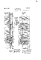
- Fig. l is a broken vertical transverse section of a portion of a freight car showing, in side elevation, my improved ladder mechanism applied thereon, portions of the mechanism bein broken away and shown in section;
- Fig. 2 is a broken front elevation of the device as shown in Fig. 1, portions being broken away and shown in section;
- Fig. 3 is a broken sectional view showing the manner in which the movable ladder section is movable from operative to inoperative positions;
- Fig. 4 is a bro-ken back view of the approach step and operating mechanism as mounted upon a freight car;
- Fig. 5 is a view similar to Fig. the ladder section and approach step moved to operative position
- Fig. 6 is a front elevation of the mechanism as shown in Fig. 5;
- Fig. 7 is a broken plan view partly in section of the latch and its actuating crank shaft.
- Fig. 8 is a transverse sectional view of the movable ladder section.
- the numeral 1 is used to designate in general a railway freight car having aside wall 2 and floor 3 of the ordinary construction.
- the wall 2 is provided with a ladder whereby persons may ascend to the top of the freight car or descend from the car to the ground, said ladder preferably comprising an upper portion 4 mounted in stationary position upon the upper portion of the wall, and a lower movable section 6 mounted upon the wall 2 below the stationary portion 4.
- the upper stationary portion of the ladder is provided with suitable rungs 7, and is mounted upon outwardly extending supporting standards 8 whereby the rungs are held in spaced relation to the wall 2.
- the lower or movable ladder section 6 is provided with similar rungs 7 and is mounted by means of links 9, each pivoted at one end upon the ladder section 6 in any convenient manner, and pivoted 1, showlng .M
- the movable section 6 is arranged to occupy a normal position with the side members and the rungs 7 in proximate relation to the wall 2 whereby the section is rendered inoperative for climbing onto or descending from the car.
- the links 9 are arranged to swing outwardly from a normal position in proximate relation to the sides of the ladder section 6, and against the wall 2, to an outwardly extending position, the links being of a length such that when extending outwardly from the wall, the section 6 will be disposed in an operative position substantially in the same plane with the stationary ladder section 4.
- the links 9 are provided with lugs 11 upon the inner ends thereof, said lugs being movable to seat against the wall 2 and limit the movement of the links 9 to their operative position.
- the upper end of the movable section 6 is arranged preferably to be received between offset extensions 12 formed upon the lower ends of the side members of the stationary section 4.
- a shaft 14 is mounted adjacent to the lower edge of the wall 2 by means of a suit-able mounting member 16 provided with bearing portions 16 engaging the shaft at points adjacent to opposite ends thereof.
- the shaft 14 is provided with a cam member 17 secured thereon.
- the member 17 is provided with a link 18 havingone end pivotally connected to the member 17 and the other end pivotally connected to the lowerend of one of the side members of the movable ladder section 6, the member 17 being movableby means of the shaft 14 to actuate the link .18 and thereby move the ladder section between its inoperative .position as shown in Fig. 1 and its operative position as shown in Fig. 5 of the drawings.
- the relative positions of the ladder section 6 are shown in dotted and in fulllines in Fig. 3 of the drawings.
- One end of the shaft 14 is squared or otherwise shaped as at 20 to receive a suitable turning implement 19.
- Spring means such as a suitable torsion spring 21 is mounted in connection with the shaft 14: to normally turn said shaft and the member 18 to a position such that the ladder section 6 is moved and held in its inoperative position.
- An approach step 22 is pivotally mounted below the lower end of the ladder section 6 at the bottom of the wall 2, the step preferably being mounted upon the shaft 1 1 in pivotally' movable relation thereto.
- a crank member 23 is mountedin back of the step 22, preferably upon asuitable mounting member 24 secured upon the under side of the car floor 3.
- the member 23 is provided with an arm 26 connected to the step 22 by means of a connecting link or yoke member 27, the member 27 being pivotally connector at opposite ends to the arm 26 and to the step 22 respectively.
- the crank member 23 is also provided with an arm 28 connected to the cam member 17 by means of a link 29 whereby movement of the shaft 14 and cam member 17 will be imparted through the crank member 23 and yoke 27 to the step 22.
- the stop member 22 is arranged to normally occupy a. position extending inwardly under the car 1, as indicated in Fig. 1 of the drawings, and is movable by means of the cam 17 and the intermediate connections to an operative outwardly extending position as indicated in Fig. 5, when the shaft 14: is moved to actuate the ladder section 6 to its operative position.
- the shaft 14- is provided with a stop member 31 having a detent '32 formed thereon.
- a latch member 33 is mounted adjacent to the stop member 31, said member 33 being provided with a latch portion 34: arranged to engage the detent 32 and prevent return movement of the member 31 and the shaft 14 after the shaft ha been moved to actuate the ladder section 6 and step 22 to their operative positions.
- the latch member 31 is
- the latch member 33 is also engaged by an actuating rod 38 extending upwardly along the Wall 2 at one side of the ladder section 6 to a point adjae cent to the top of said ladder section.
- actuating lever 39 is pivot-all mounted adjacent to the top of the rod 38 and in engagement therewith whereby therod 38 may be moved to actuate the latch member33 to releasing position, as hereinafter more fully described.
- Theupper end of the movable ladder section 6 is provided with a foot piece 4:1 211? rangedto receive the weight of a person doscending the ladder when the section. (Sis in its inoperative position, whereby the weight of such person operates to swing the section 6 outwardly to operative position, the movement of the ladder being imparted through the link 18 and cam member 17 to the shaft 14
- the cam member 17, together with the latch member 33 and link 29 is covered by a suitable housing 42, andthe rod 38 is enclosed within a tubular casing 43.
- the shaft 14' is normally moved by the spring 21 to move the cam member 17 to the position indicated in Fig. 1 of the drawings, thereby causing theladder section to be moved inwardly into proximatereoutwardly to its operative position.
- the step occupies a position inaccessible to a person seeking to ascend the ladder onto the car 1, and at the same time, the rungs 7 of the ladder section 6 are disposed in proximate relation to the wall so that they cannot be grasped or afford an adequate hand or foot hold by which a person could ascend onto the car.
- the shaft 1 1 When a trainman desires to ascend the ladder, the shaft 1 1 is turned, by means of the implement 19, to move the ladder section and step to operative positions.
- the ordinary brake club commonly carried by trainmen is preferably provided. with a soclret arranged to fit the squared end of the shaft.
- the implement 1,9 is applied in a substantially horizontally disposed position so that the weight of the trainmen may be elfectually applied through the leverage of the implement 19 to turn the shaft.
- the link 18 As the shaft is turned, the link 18 is moved to swing the ladder section 6 outwardly to its operative position, and at the same time, the link 29 moved to operate through the crank member 23 and link 27 to swing the step outwardly to operative position, as shown in Fig.
- the detent 32 is moved past the latch portion 34 of the member 33, the member 33 being raised against the force of gravity as the detent passes the portion 34, and being immediately moved downward- 1y by gravity to prevent return movement of the detent past the latch portion 34.
- the step 22 and ladder portion. 6 will thus be held in an operative position whereby the trainman may readily ascend onto the car.
- trainmen may readily operate the ladder section 6 and step 22 either from below or from above as required, and that the section and step may be released either from above or below to permit the parts to be re turned to normal inoperative position.
- My device is primarily useful as a means to prevent unauthorized persons from I mounting onto freight cars, and to guard against the theft of goods from freight cars while in transit.
- a common practice of freight car thieves is to swing aboard a freight 30 train as it is leaving a station. They then break the seals and open a car door from the top of the car and swing into the opened car from above. The thieves then throw the goods out along the right of way to be 001- 8 lected by Confederates or by the thieves themi A selves at a later time.
- My improved device renders it extremely ditlicult, if not impossible, for a thief to board a moving freight train, and thereby constitutes an effectual guard against the theft of goods in transit.
- a freight car ladder comprising a sta tionary section mounted upon a side of a freight car adjacent to the top thereof; a movable section mounted upon the wall belov the stationary section; and means for moving said movable section between operative and inoperative positions relative to the Wall of the freight car.
- a freight car ladder comprising a star. tionary section mounted upon a side of a freight car adjacent to the top thereof; a movable section mounted upon the wall below the stationary section; and means operable from the top and from thebottom of said 212- movable section to move the same between operative and inoperative positions relative to the wall of the freight car.
- a frieght car ladder comprising a sta- 12 tionary section mounted upon a side of a freight car adjacent to the top thereof; a movable section mounted upon the wall below the stationary section; means to normally hold the movable section in an inoperative E position in proximate relation to the wall;
- a freight car ladder comprising a stationary section mounted upon a side of afreight car adjacent to the top thereof; a movable section mounted upon the wall below the stationary section; means to normally hold the movable section in an inoperative position in proximate relation to the wall; and means operable from the top and from the bottom of the movablesection to move the same to an operative position in spaced relation to the wall.
- a freight car ladder comprising a stationary section mounted upon aside of a freight car adjacent to the top thereof; a movable section mounted upon the wall below the stationary section; means to normally hold the movable section in an inoperative position in proximate relation to the w ll; means operable from the top and'from the bottom of the movable section to move the same to an operative position in spaced relation to the wall; retaining means to secure the movable section in operative position; and means to move the retaining means to a re leasing position to release the movable section to its inoperative position.
- a freight car ladder comprising a stationary section mounted upon a side of a freight car adjacent to the top thereof; a movable section mounted upon the wall below the stationary section; means to normally hold the movable section in an inoperative position in proximate relation to the wall; means operable from the top and from the bottom of the movable section to move the same to an operative position in spaced relation to the wall; retaining means to secure the movable section in operative position and means independently operable from the top and from the bottom of the movable section to move the retaining means to a releasing position to release the movable section to its inoperative position.
- T he combination with a freight car of amovable ladder section mounted upon a wall of the car, said section being provided with links pivoted at one end upon the ladder section and at the opposite end upon the wall'to support the ladder in an inoperative position in proximate relation to the wall the links being movable to support the section in an operative position outwardly spaced.
Landscapes
- Engineering & Computer Science (AREA)
- Mechanical Engineering (AREA)
- Ladders (AREA)
Description
April 5, 1932.
E. NEWCASTLE 1,852,430
FREIGHT CAR LADDER Filed Feb. 9, 1951 2 Sheets-Sheet l HI 'HIHIIIIKHIW HHH I b INVENTOR.
EDWARD NEWCASTLE.
///s Afro/ME):
April 5, 1932. E. NEWCASTLE FREIGHT CAR LADDER Filed Feb. 9, 1931 2 Sheets-Sheet //VVENTOR EDWARD NEWCASTLE Patented Apr. 5, 1932 EDWARD NEWCASTLE, OF SAN FRANCISCO, CALIFORNIA FREIGHT CAR LADDER Application filed February 9, 1931.
My invention relates to improvements in ladders for railway freight cars and the like, wherein a ladder section and an approach step are mounted upon the lower portion of a car Wall, said ladder section and step being normally held in an inoperative position to prevent ascent thereon by unauthorized persons onto the car, and being movable to operative positions when required.
The primary object of my invention is to provide an improved ladder for railway freight cars and the like to normally hinder the ascent of unauthorized persons onto such cars.
Another object is to provide an improved ladder which is normally held in an inoperative position upon a wall and which may be readily moved to an operative position when required.
A further object is to provide an improved device of the character described provided with an approach step movable to operative and inoperative positions, the step being normally disposed in an inoperative position to u prevent ascent onto the ladder.
Another object is to provide an improved ladder of the character described which may be readily operated either from above or below to move the ladder between its operative and inoperative positions in a prescribed manner.
A. further object is to provide an improved device of the character described which may be effectually held in operative position when required, and which maybe released and automatically returned to a normal inoperative position either from below or above.
A further object is to provide an improved device of simple and eiiicient construction a: and operation and which can be economically installed.
A. still further object is to provide improved mechanism of the character described cmliodying improved details of construction 4 and arrangement to facilitate the manufacture, installation, and operation of the device.
I accomplish these and other objects by means of the improved device disclosed in the drawings forming a part of the present application wherein like characters of reference Serial No. 514,494.
are used to designate similar parts through out the specification and drawings, and in which 4 Fig. l is a broken vertical transverse section of a portion of a freight car showing, in side elevation, my improved ladder mechanism applied thereon, portions of the mechanism bein broken away and shown in section;
Fig. 2 is a broken front elevation of the device as shown in Fig. 1, portions being broken away and shown in section;
Fig. 3 is a broken sectional view showing the manner in which the movable ladder section is movable from operative to inoperative positions;
Fig. 4 is a bro-ken back view of the approach step and operating mechanism as mounted upon a freight car;
Fig. 5 is a view similar to Fig. the ladder section and approach step moved to operative position;
Fig. 6 is a front elevation of the mechanism as shown in Fig. 5;
Fig. 7 is a broken plan view partly in section of the latch and its actuating crank shaft; and
Fig. 8 is a transverse sectional view of the movable ladder section.
Referring to the drawings, the numeral 1 is used to designate in general a railway freight car having aside wall 2 and floor 3 of the ordinary construction.
The wall 2 is provided with a ladder whereby persons may ascend to the top of the freight car or descend from the car to the ground, said ladder preferably comprising an upper portion 4 mounted in stationary position upon the upper portion of the wall, and a lower movable section 6 mounted upon the wall 2 below the stationary portion 4. The upper stationary portion of the ladder is provided with suitable rungs 7, and is mounted upon outwardly extending supporting standards 8 whereby the rungs are held in spaced relation to the wall 2. The lower or movable ladder section 6 is provided with similar rungs 7 and is mounted by means of links 9, each pivoted at one end upon the ladder section 6 in any convenient manner, and pivoted 1, showlng .M
at the opposite end upon suitable supporting members 10 secured upon the wall.
The movable section 6 is arranged to occupy a normal position with the side members and the rungs 7 in proximate relation to the wall 2 whereby the section is rendered inoperative for climbing onto or descending from the car. The links 9 are arranged to swing outwardly from a normal position in proximate relation to the sides of the ladder section 6, and against the wall 2, to an outwardly extending position, the links being of a length such that when extending outwardly from the wall, the section 6 will be disposed in an operative position substantially in the same plane with the stationary ladder section 4. The links 9 are provided with lugs 11 upon the inner ends thereof, said lugs being movable to seat against the wall 2 and limit the movement of the links 9 to their operative position. The upper end of the movable section 6 is arranged preferably to be received between offset extensions 12 formed upon the lower ends of the side members of the stationary section 4.
A shaft 14 is mounted adjacent to the lower edge of the wall 2 by means of a suit-able mounting member 16 provided with bearing portions 16 engaging the shaft at points adjacent to opposite ends thereof. The shaft 14 is provided with a cam member 17 secured thereon. The member 17 is provided with a link 18 havingone end pivotally connected to the member 17 and the other end pivotally connected to the lowerend of one of the side members of the movable ladder section 6, the member 17 being movableby means of the shaft 14 to actuate the link .18 and thereby move the ladder section between its inoperative .position as shown in Fig. 1 and its operative position as shown in Fig. 5 of the drawings. The relative positions of the ladder section 6 are shown in dotted and in fulllines in Fig. 3 of the drawings. One end of the shaft 14 is squared or otherwise shaped as at 20 to receive a suitable turning implement 19. Spring means, such as a suitable torsion spring 21 is mounted in connection with the shaft 14: to normally turn said shaft and the member 18 to a position such that the ladder section 6 is moved and held in its inoperative position.
An approach step 22 is pivotally mounted below the lower end of the ladder section 6 at the bottom of the wall 2, the step preferably being mounted upon the shaft 1 1 in pivotally' movable relation thereto. A crank member 23 is mountedin back of the step 22, preferably upon asuitable mounting member 24 secured upon the under side of the car floor 3. The member 23 is provided with an arm 26 connected to the step 22 by means of a connecting link or yoke member 27, the member 27 being pivotally connector at opposite ends to the arm 26 and to the step 22 respectively. The crank member 23 is also provided with an arm 28 connected to the cam member 17 by means of a link 29 whereby movement of the shaft 14 and cam member 17 will be imparted through the crank member 23 and yoke 27 to the step 22. The stop member 22 is arranged to normally occupy a. position extending inwardly under the car 1, as indicated in Fig. 1 of the drawings, and is movable by means of the cam 17 and the intermediate connections to an operative outwardly extending position as indicated in Fig. 5, when the shaft 14: is moved to actuate the ladder section 6 to its operative position.
The shaft 14- is provided with a stop member 31 having a detent '32 formed thereon. A latch member 33 is mounted adjacent to the stop member 31, said member 33 being provided with a latch portion 34: arranged to engage the detent 32 and prevent return movement of the member 31 and the shaft 14 after the shaft ha been moved to actuate the ladder section 6 and step 22 to their operative positions. The latch member 31. is engaged by a crank 36 formed upon' a shaft 37 extending transversely above the latch member, said shaft 37 being provided with an actuating lever The crank 36 and lever 37 are so disposed that the action of gravity operatesgto turn the shaft to a normal position vu such that the crank 36 operates to press the latch member 33 downwardly to position the latch portion 34iin the path of the detent 32 whereby the detent will be automatically engaged and held against return after passing the latch portion 34. The latch member 33 is also engaged by an actuating rod 38 extending upwardly along the Wall 2 at one side of the ladder section 6 to a point adjae cent to the top of said ladder section. An
actuating lever 39 is pivot-all mounted adjacent to the top of the rod 38 and in engagement therewith whereby therod 38 may be moved to actuate the latch member33 to releasing position, as hereinafter more fully described.
Theupper end of the movable ladder section 6 is provided with a foot piece 4:1 211? rangedto receive the weight of a person doscending the ladder when the section. (Sis in its inoperative position, whereby the weight of such person operates to swing the section 6 outwardly to operative position, the movement of the ladder being imparted through the link 18 and cam member 17 to the shaft 14 The cam member 17, together with the latch member 33 and link 29 is covered by a suitable housing 42, andthe rod 38 is enclosed within a tubular casing 43. i
In, operation, the shaft 14' is normally moved by the spring 21 to move the cam member 17 to the position indicated in Fig. 1 of the drawings, thereby causing theladder section to be moved inwardly into proximatereoutwardly to its operative position.
lation to the wall 2, and at the same time moving the step 22 inwardly to its inoperative position, as indicated in Fig. 1 of the drawmgs. In this position, the step occupies a position inaccessible to a person seeking to ascend the ladder onto the car 1, and at the same time, the rungs 7 of the ladder section 6 are disposed in proximate relation to the wall so that they cannot be grasped or afford an adequate hand or foot hold by which a person could ascend onto the car.
When a trainman desires to ascend the ladder, the shaft 1 1 is turned, by means of the implement 19, to move the ladder section and step to operative positions. For this purpose, the ordinary brake club commonly carried by trainmen is preferably provided. with a soclret arranged to fit the squared end of the shaft. The implement 1,9 is applied in a substantially horizontally disposed position so that the weight of the trainmen may be elfectually applied through the leverage of the implement 19 to turn the shaft. As the shaft is turned, the link 18 is moved to swing the ladder section 6 outwardly to its operative position, and at the same time, the link 29 moved to operate through the crank member 23 and link 27 to swing the step outwardly to operative position, as shown in Fig. As the shaft 1-61 is turned, the detent 32 is moved past the latch portion 34 of the member 33, the member 33 being raised against the force of gravity as the detent passes the portion 34, and being immediately moved downward- 1y by gravity to prevent return movement of the detent past the latch portion 34. The step 22 and ladder portion. 6 will thus be held in an operative position whereby the trainman may readily ascend onto the car.
When the trainman has ascended until his weight is supported upon the stationary ladder section 1-, he presses the lever 39 in a manner to move the same to actuate the rod 38 and thereby lift the latch member 83 to a releasing poistion out of engagement with the det-ent 32. As soon as the detent is re leased, the spring 21 operates to immediately return the shaft 14:, and the connections actuated thereby, to normal inoperative position.
Should a trainman desire to descend from the top of the car 1, he descends in the ordinary manner until he can reach and apply his weight upon the foot piece 41, thereby pressing the ladder section 6 downwardly and The movement of the lad d-er section 6 actu ates the cam member 17 and shaft 14 in the same manher as when the shaft 14 is turned by means of the implement 19, thereby causing the step 22 to be swung outwardly to operative position. Upon reaching the ground, the train man raises the lever 35 sulticiently to more the crank 36 and latch member 33 engaged thereby to releasing position. thereby permitting the step and ladder section to be automatically returned to their inoperative positions by the spring 21.
From the above explanation, it will be observed that trainmen may readily operate the ladder section 6 and step 22 either from below or from above as required, and that the section and step may be released either from above or below to permit the parts to be re turned to normal inoperative position.
My device is primarily useful as a means to prevent unauthorized persons from I mounting onto freight cars, and to guard against the theft of goods from freight cars while in transit. A common practice of freight car thieves is to swing aboard a freight 30 train as it is leaving a station. They then break the seals and open a car door from the top of the car and swing into the opened car from above. The thieves then throw the goods out along the right of way to be 001- 8 lected by Confederates or by the thieves themi A selves at a later time. My improved device renders it extremely ditlicult, if not impossible, for a thief to board a moving freight train, and thereby constitutes an effectual guard against the theft of goods in transit.
While I have illustrated what I now regard as the preferred embodiment of my invention, and have illustrated the device only as applied upon railway freight cars, the device is, of course, subject to modification in numerous details of construction and may be applied to other purposes without departing from the spirit of my invention. I therefore do not wish to be restricted to the specific 10o construction and method of application here- Z in disclosed, but desire to avail myself of all modifications which may fall within the scope of the appended claims.
Having thus described my invention, what I claim as new and desire to secure by Letters Patent is 1. A freight car ladder comprising a sta tionary section mounted upon a side of a freight car adjacent to the top thereof; a movable section mounted upon the wall belov the stationary section; and means for moving said movable section between operative and inoperative positions relative to the Wall of the freight car.
2. A freight car ladder comprising a star. tionary section mounted upon a side of a freight car adjacent to the top thereof; a movable section mounted upon the wall below the stationary section; and means operable from the top and from thebottom of said 212- movable section to move the same between operative and inoperative positions relative to the wall of the freight car.
3. A frieght car ladder comprising a sta- 12 tionary section mounted upon a side of a freight car adjacent to the top thereof; a movable section mounted upon the wall below the stationary section; means to normally hold the movable section in an inoperative E position in proximate relation to the wall;
and means to move the movable section to an operative position in spaced relation to the wall.
4. A freight car ladder comprising a stationary section mounted upon a side of afreight car adjacent to the top thereof; a movable section mounted upon the wall below the stationary section; means to normally hold the movable section in an inoperative position in proximate relation to the wall; and means operable from the top and from the bottom of the movablesection to move the same to an operative position in spaced relation to the wall.
5. A freight car ladder comprising a stationary section mounted upon aside of a freight car adjacent to the top thereof; a movable section mounted upon the wall below the stationary section; means to normally hold the movable section in an inoperative position in proximate relation to the w ll; means operable from the top and'from the bottom of the movable section to move the same to an operative position in spaced relation to the wall; retaining means to secure the movable section in operative position; and means to move the retaining means to a re leasing position to release the movable section to its inoperative position.
6. A freight car ladder comprising a stationary section mounted upon a side of a freight car adjacent to the top thereof; a movable section mounted upon the wall below the stationary section; means to normally hold the movable section in an inoperative position in proximate relation to the wall; means operable from the top and from the bottom of the movable section to move the same to an operative position in spaced relation to the wall; retaining means to secure the movable section in operative position and means independently operable from the top and from the bottom of the movable section to move the retaining means to a releasing position to release the movable section to its inoperative position.
7. The combination with a freight car, of a movable ladder section mounted upon a wall of the car; a step pivotally mounted at the lower edge of the wall in substantial alinement with the ladder section; means normal- 1y holding the ladder section and step in inoperative positions to prevent the ascent or descent of persons along the ladder section; and means to move the ladder section and step to operative positions. 7
8. The combination with a freight car of a movableladder section mounted upon a wall of the car, said section being provided with links pivoted at one end upon the ladder section and at the opposite end upon the wall to support the ladder in an inoperat ve position in proximate relation to the'wall the links being movable to support the section in an operative position outwardly spaced from the wall; a shaft mounted below the lower edge of the wall and provided with means whereby the shaft may be rotated; an approach step pivotally mounted upon the shaft; a cam mounted upon the shaft; a link connected to the cam and to the ladder section to move the ladder between its operative and inoperative positions when the shaft and cam are moved through a portion of a revolution; and links connecting the cam with the approach step to move said step between operative and inoperative positions simultaneously with the movement of the ladder sectionto corresponding positions.
9. Thecombination with a freight car, of a movable ladder section mounted upon a wall of the'car, said section being provided with links pivoted at one end upon the ladder section and at the opposite end upon the wall to support the ladder. in an inoperative position in proximate relation to the wall, the links being movable to support the section in an operative position outwardly spaced from the wall; a shaft mounted below the lower edge of the wall and provided with means whereby the shaft may be rotated; an approach step pivotally mounted upon the shaft; a cam mounted upon the shaft; alink connect-er to the cam and to the ladder section to move the ladder between its operative and inoperative positions when the shaft and cam are moved through a portion of a revolution; links connecting the cam with the approach step to move said step between opera tive and inoperative positionssimultaneously with the movement of the ladder section to corresponding positions; spring means to normally actuatethe shaft and cam to move the ladder section and step to their inoperative positions; and latch means to releasably securethe shaft and cam against return movement when moved to actuate the ladder section and step to operative position.
10. T he combination with a freight car, of amovable ladder section mounted upon a wall of the car, said section being provided with links pivoted at one end upon the ladder section and at the opposite end upon the wall'to support the ladder in an inoperative position in proximate relation to the wall the links being movable to support the section in an operative position outwardly spaced. from the wall; a shaft mounted below the lower edge of the wall an d provided with means whereby the shaft may be rotated; an approach step pivotally mounted upon the shaft; a cam mounted upon the shaft; a link connected to the cam and to the ladder section to move the ladder between its operative and inoperative positions when the shaft and cam are moved through a portion of a revolution ;'l1nks con-' ncc ting the cam with the approach step 'to move said step between operative and 111- operative positions simultaneously Wlllll the movement of the ladder section to corresponding positions; spring means to normally aetuate the shaft and cam to move the ladder section and step to their inoperative positions. latch means to releasably secure the shaft and cam against return movement when moved to actuate the ladder section and step to operative position; and means operable from the top and from the bottom of the ladder section to move the latch means to releasing position.
11. The combination with a freight car, of a movable ladder section mounted upon a Wall of the car, said section being provided with links pivoted at one end upon the ladder section and at the opposite end upon the wall to support the ladder in an inoperative position in proximate relation to the wall, the links being movable to support the section in an operative position outwardly spaced from the wall; a shaft mounted below the lower edge of the wall and provided with means whereby the shaft may be rotated; an approach step pivotally mounted upon the shaft; a cam mounted upon the shaft; a link connected to the cam and to the ladder section to move the. ladder between its operative and inoperative positions when the shaft and cam are moved through a portion of a revolution; links connecting the cam With the approach step to move said step between operative and inoperative positions simultaneously With the movement of the ladder section to corresponding positions; and means upon the upper end of the ladder section for moving said ladder section to operative position from above.
In witness whereof, I hereunto set my signature.
EDWARD NEWCASTLE.
Priority Applications (1)
| Application Number | Priority Date | Filing Date | Title |
|---|---|---|---|
| US514494A US1852430A (en) | 1931-02-09 | 1931-02-09 | Freight car ladder |
Applications Claiming Priority (1)
| Application Number | Priority Date | Filing Date | Title |
|---|---|---|---|
| US514494A US1852430A (en) | 1931-02-09 | 1931-02-09 | Freight car ladder |
Publications (1)
| Publication Number | Publication Date |
|---|---|
| US1852430A true US1852430A (en) | 1932-04-05 |
Family
ID=24047412
Family Applications (1)
| Application Number | Title | Priority Date | Filing Date |
|---|---|---|---|
| US514494A Expired - Lifetime US1852430A (en) | 1931-02-09 | 1931-02-09 | Freight car ladder |
Country Status (1)
| Country | Link |
|---|---|
| US (1) | US1852430A (en) |
Cited By (3)
| Publication number | Priority date | Publication date | Assignee | Title |
|---|---|---|---|---|
| US4542805A (en) * | 1984-08-03 | 1985-09-24 | Hamlin David A | Automatically retractable, rotatable step assembly |
| US20160288898A1 (en) * | 2015-04-01 | 2016-10-06 | B/E Aerospace, Inc. | Stowable elevated footstep for an aircraft galley |
| DE102022200380A1 (en) | 2022-01-14 | 2023-07-20 | Siemens Mobility GmbH | Tread assembly and method of operating the tread assembly |
-
1931
- 1931-02-09 US US514494A patent/US1852430A/en not_active Expired - Lifetime
Cited By (4)
| Publication number | Priority date | Publication date | Assignee | Title |
|---|---|---|---|---|
| US4542805A (en) * | 1984-08-03 | 1985-09-24 | Hamlin David A | Automatically retractable, rotatable step assembly |
| US20160288898A1 (en) * | 2015-04-01 | 2016-10-06 | B/E Aerospace, Inc. | Stowable elevated footstep for an aircraft galley |
| US9975621B2 (en) * | 2015-04-01 | 2018-05-22 | B/E Aerospace, Inc. | Stowable elevated footstep for an aircraft galley |
| DE102022200380A1 (en) | 2022-01-14 | 2023-07-20 | Siemens Mobility GmbH | Tread assembly and method of operating the tread assembly |
Similar Documents
| Publication | Publication Date | Title |
|---|---|---|
| US1852430A (en) | Freight car ladder | |
| US1537506A (en) | Collapsible fire escape | |
| US1196568A (en) | Double-decked car. | |
| US772741A (en) | Passenger-car. | |
| US653769A (en) | Car-step. | |
| US1397294A (en) | Automatic raising and lowering steps | |
| US1141064A (en) | Auxiliary step for car-platforms. | |
| US945748A (en) | Emergency-exit for suspension-railway cars. | |
| US949739A (en) | Folding gate. | |
| US1119200A (en) | Train-protector. | |
| US116223A (en) | Improvement in station-indicators | |
| US1801973A (en) | Step and trap construction for passenger cars | |
| US956500A (en) | Car-vestibule door. | |
| US540797A (en) | Vehicle-step | |
| US748178A (en) | Door-opening device. | |
| US924537A (en) | Extension car-step. | |
| US490344A (en) | The norsis peters co | |
| US536708A (en) | Car-fender | |
| US845750A (en) | Vestibule-car platform. | |
| US539735A (en) | Samuel a | |
| US477075A (en) | Safety-car | |
| US958657A (en) | Car-step. | |
| US1164530A (en) | Passenger-car. | |
| US1136581A (en) | Folding car-steps. | |
| US1235603A (en) | Safety mechanism for elevator-shaft doors. |